
This work is licensed
under a
Creative Commons
Attribution-NonCommercial-
ShareAlike 4.0
International License.
 This project is licensed under a Creative Commons Attribution-NonCommercial-ShareAlike 4.0 International License. For more information on this type of license please visit Week 18: Invention, Intellectual property & Income.
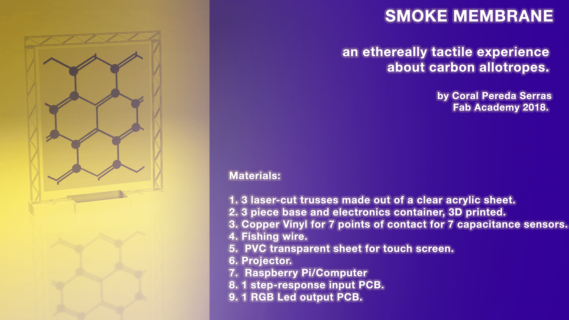
For my Fab Academy final project, I want to build a bioart interactive installation.
Why: The idea for the first proposed project was born after last summer I survived a house fire in Chicago, IL. As the initial shock of the event wore off, I came to the realization of how devastating smoke damage can be. The day after the fire, I returned to the apartment to try and retrieve some of my belongings. The space was in full darkness that was only accentuated by the soot-covered walls. I then captured photographs that were abstracted by the poor lighting conditions. I therefore decided to work exclusively with the images that were out of focus and/or have motion blur. I believe their abstraction is more representative of the devastation of the fire than perfect images could ever be. The images that were supposed to be evidentiary ultimately fail to accomplish their goal as their digital limitations get in the way. These artifacts render the medium obsolete in a situation that was already barely salvageable. This project explores the frustration and anger following the fire and photography's failure to capture that traumatic isolation.
What: I am interested in highlighting how destructive and yet at the same time attractive soot can be. I want viewers to be immersed in that dichotomy and to be able to alter it. My goal through my artist practice is to create a space and environment in which people can share reactions. The installation will be made up of a membrane-like object potentially 3D printed. On that I will project my own abstract images of the fire and microscopic images of soot.
Sample Images:
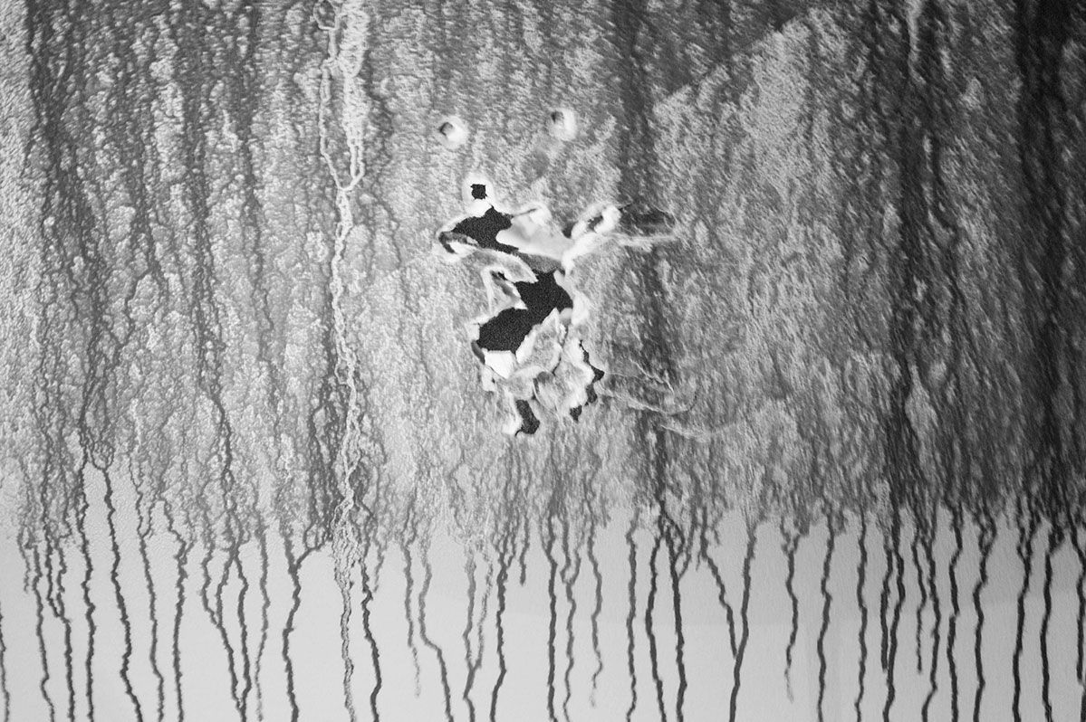
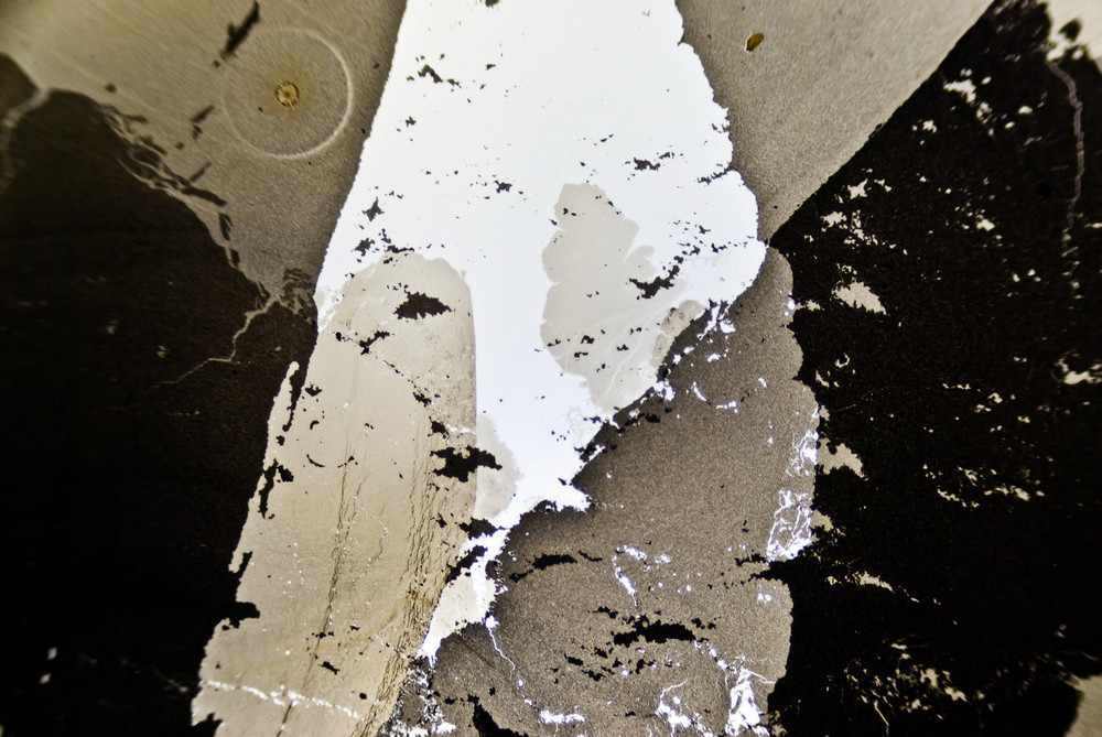
At this a stage, it will become hard to tell which one are the close-ups and which ones are the apartment ones. I want to work with sensors to that the image projected changes or is altered when the membrane is touched.
Find below a couple of installations that deal with similar concepts:
Metamorphy 2
Research the biological composition of soot. What makes it toxic?
Please refer to Week 19: Project Development
Out of pocket:
5 mm thick acryllic sheet, 60x50mm. (Available at Servei Estacio: 23.72 EUR)
Transparent PVC for screen, 70x100mm. (Available at Servei Estacio: 3.80 EUR)
8 neopixels from a 100m strip.(Available online on Adafruit: 24.95 USD)
White jumper cables.(Available at Diotronic: 5.45 EUR)
White shrinking tubes.(Availabe on Amazon: 12.99 EUR)
Masking tape. (Available at Servei Estacio: 3 EUR)
Provided by Fab Lab BCN:
Green PVC for screen prototype.
Copper vinyl.
PCB.
Components and soldering materials.
White PLA filament.
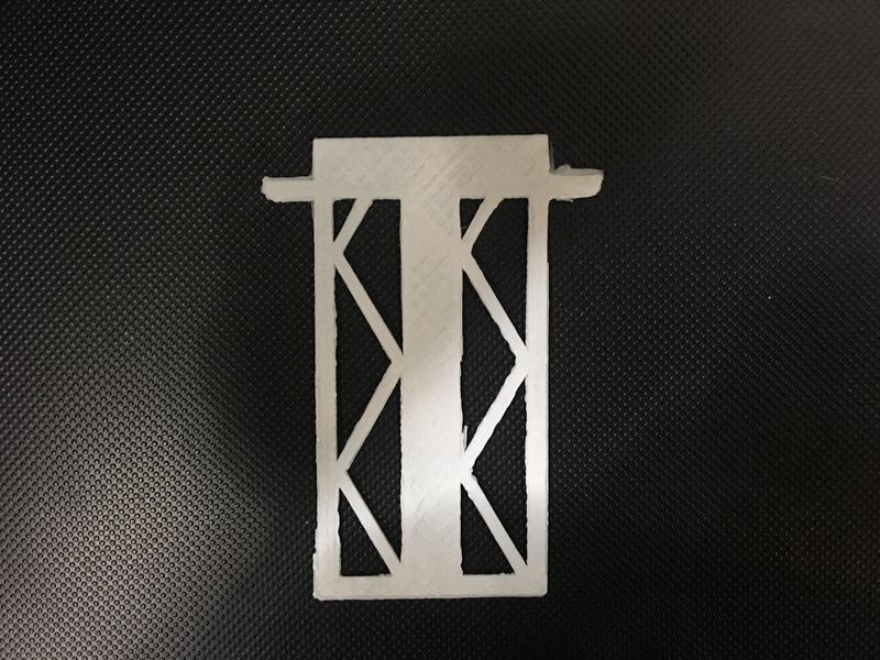
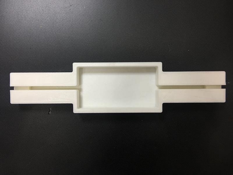
Initially, my screen's structure was meant to be developped during Week 7.
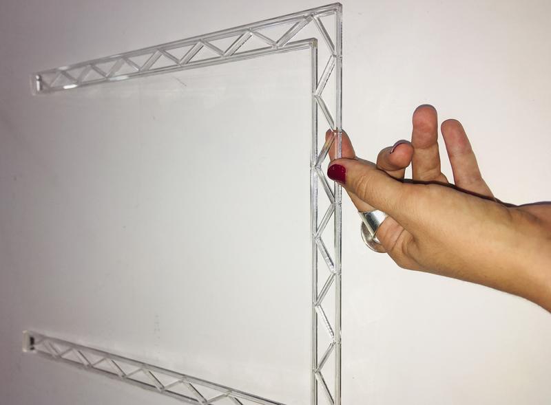
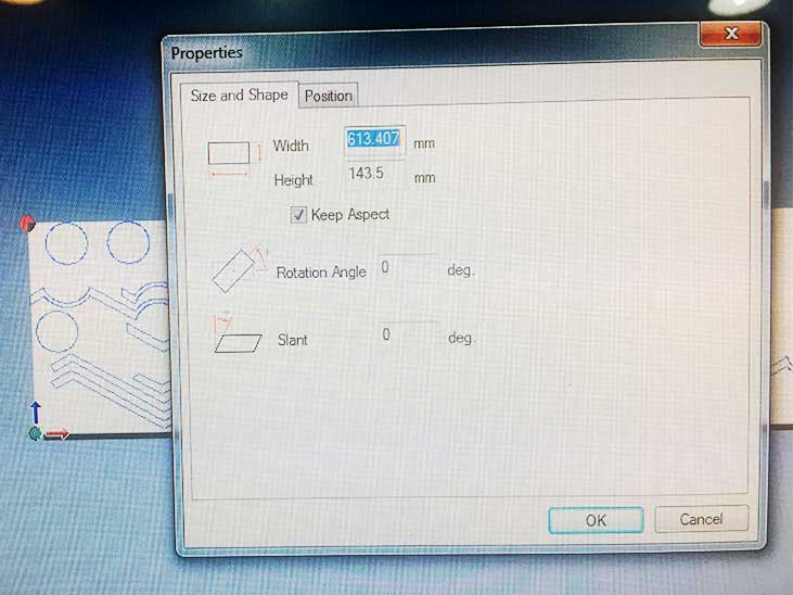
I wanted to build a large scale structure and screen. However, because of a lack of time, I had to stick to a smaller prototype for the time being. For that, I designed a rectangular structure to be laser-cut from a 5mm acryllic sheet. My structure is made up of three sides of a rectangle. Each side is 25 mm width-wise and reproduces the triangular pattern created by two bonds in a graphene molecular structure. I first divided the piece in three different sticks so as to be more efficient with the use of material. However, these were very hard to glue together and no matter what type of glue I tried, the pieces would always break apart from each other.
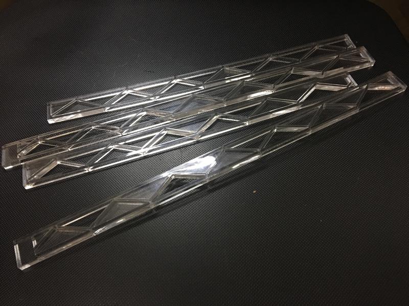
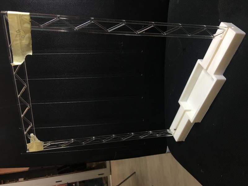
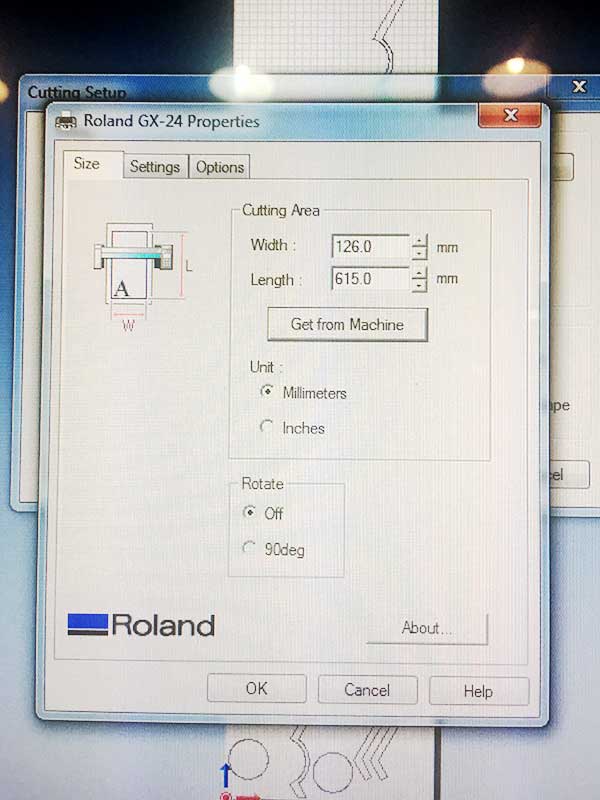
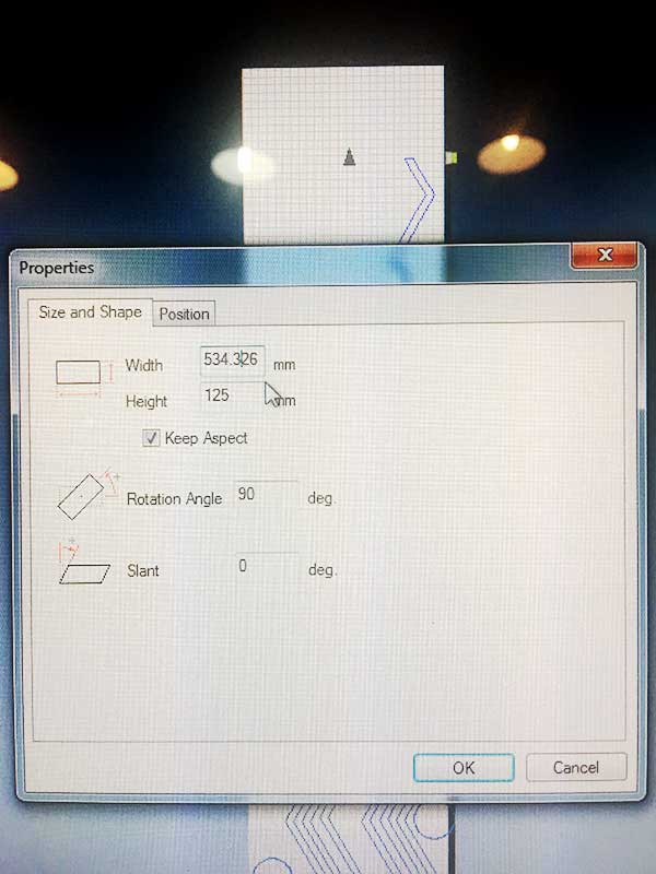
I then decided to redesign the corners where the vertical sticks met the horizontal one. I proceeded to cut the new design in a single piece. This was specially challenging since it took up a lot of space in the acryllic sheet. In addition, our laser cutter struggles a little with thicker materials. It took two four tries to find the right settings. The first, I used the following settings:
Power:100
Speed:0.5
Frequency:20 000Hz.
The laser did not go all the way through so while maintaining the position of the sheet on the machine's bed and that of the laser's head I ran the file a second time but lowered the power to 80. Some traces still didn't go all the way down. I ran the file a third time but this time, I had moved the laser's head by accident so my design was ruined. With the help of our wonderful facilities manager, Mikel Llobera, we then carefully measured the remaining space on my sheet and managed to fit a new version of the structure. Since we had already increased the power to its maximum, we reduced the speed and tested out the new settings with small circle:
Power:100
Speed:0.4
Frequency:20 000Hz.
This time we were successful!
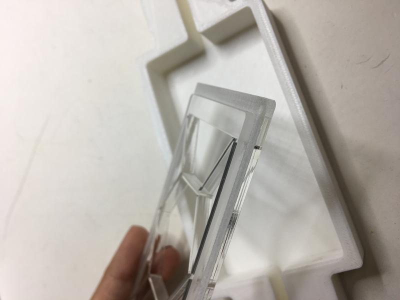
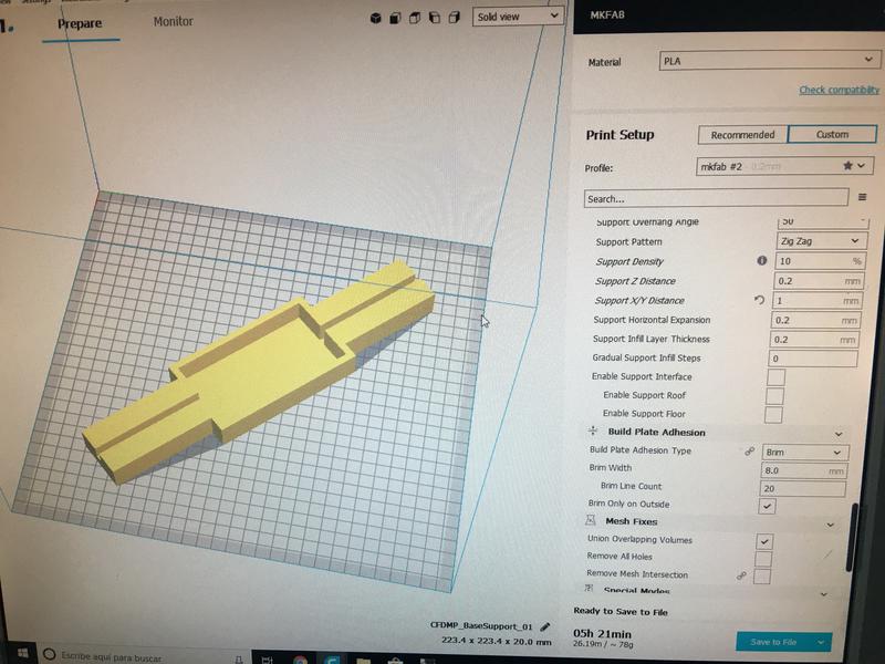
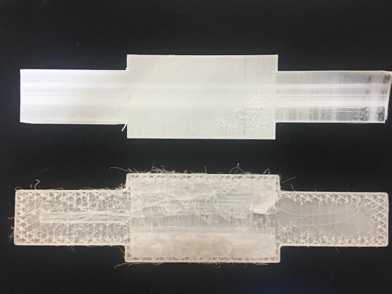
 I also decided to design a transparent lid to cover the electronics in the 3D printed part. I did so in Fusion 360 and in InDesign.
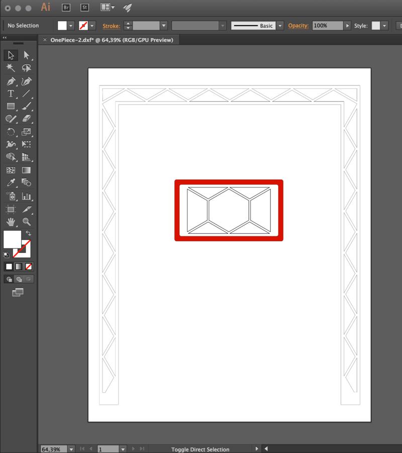 The challenge with this part was that I wanted to include a pocket to wrap around the piece so
that it would have something to hold on to. I tested a couple of settings.
The challenge with this part was that I wanted to include a pocket to wrap around the piece so
that it would have something to hold on to. I tested a couple of settings.
Raster - engrave
Power:80
Speed:5
Frequency:1 000Hz.
As seen on week 16, I experimented with different materials for my screen design. However, after a lot of trial and error, I realized I would have to go for something else. At the beginning, I confused the the capacitance sensor with the pressure sensor as seen below:
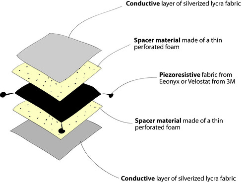
That required way too many materials and was not exactly the sensor I needed since I would not have more than one touch points. The diagram below is a more accurate representation of the needed material layout:
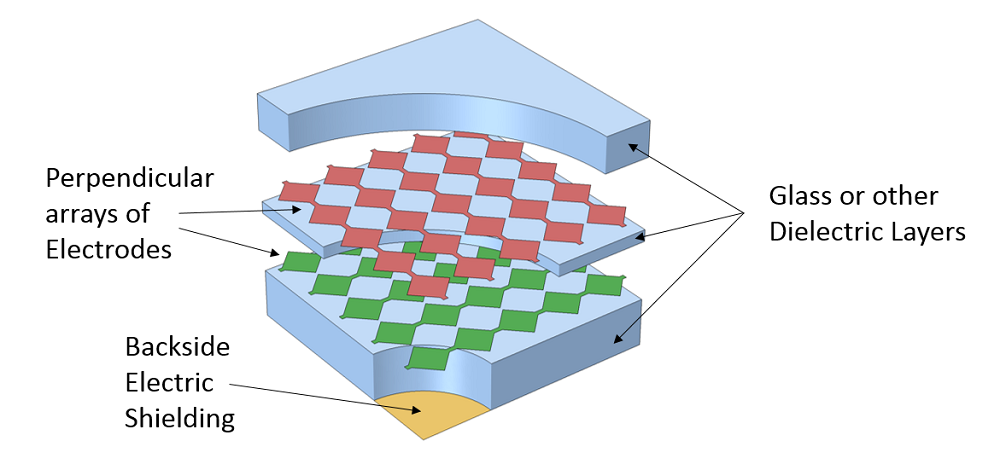
Capacitive touchscreen sensor geometry
Based on my structure design, my screen size must range between 1000 mm x 1000 mm and 800 mm x 1000 mm.
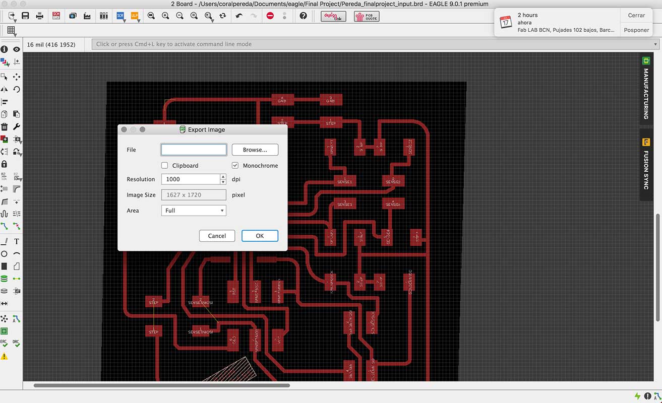
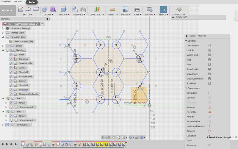 I then spent a long time building the screen design which basically translates into a huge input board.
I was trying to go for the usual graphene molecular shape. I then translated that design into a matrix similar to that of the capacitive touchscreen sensor geometry above by using Adobe Illustrator.
I then spent a long time building the screen design which basically translates into a huge input board.
I was trying to go for the usual graphene molecular shape. I then translated that design into a matrix similar to that of the capacitive touchscreen sensor geometry above by using Adobe Illustrator.
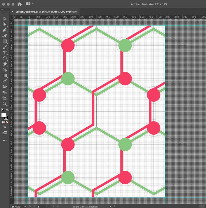
While making this design, I realized that my shape will have only 7 sensors and around 8 touchpoints.
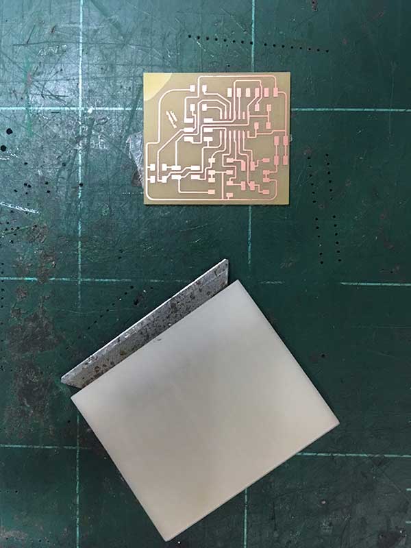
I first made a conductivity test by making a screen prototype with a piece of green light filter around our lab. I sent my .svg file to the vinyl cutter. As you can see below, some of the wrinkles in the copper did not allow for the pattern to be cut properly. This was due to the fact that there was not enough room for the copper roll to scroll freely through the cutter. Our machine sits on a table that is way too small so the roll would fold when the cutter tried to pull some more material through.
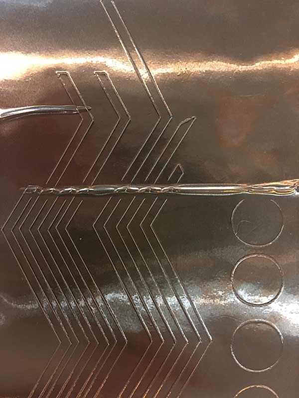
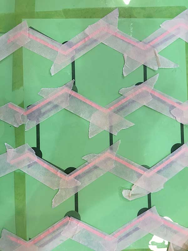
After I placed small plastic bridges between the overlapping copper tracks, I tested the screen for possible short-circuits. Then I proceeded to make the screen on the final material, a transparent plastic.
I tried to follow Matt Blackshaw's design as much as possible. Below is an image of the Eagle Schematic I ended up using.
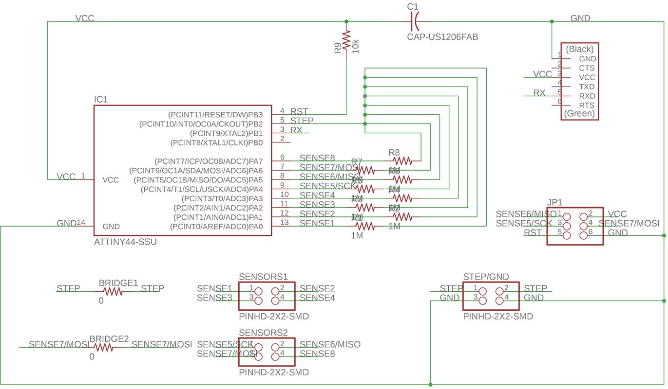
However I noticed that he forgot to connect two resistors to the microchip and use a bridge. I made sure that did not happen to me. After spending a whole day trying to route the wire without using bridge resistors, I realized I needed to be more practical. See below an example of one of the many routing alternatives I tried.
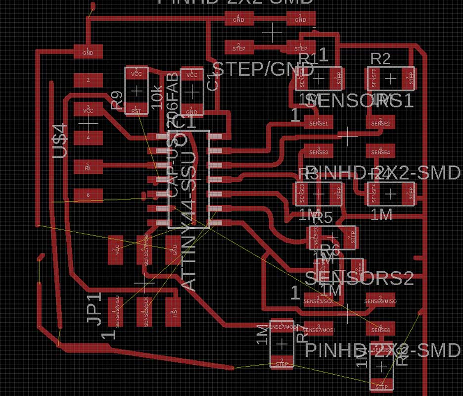
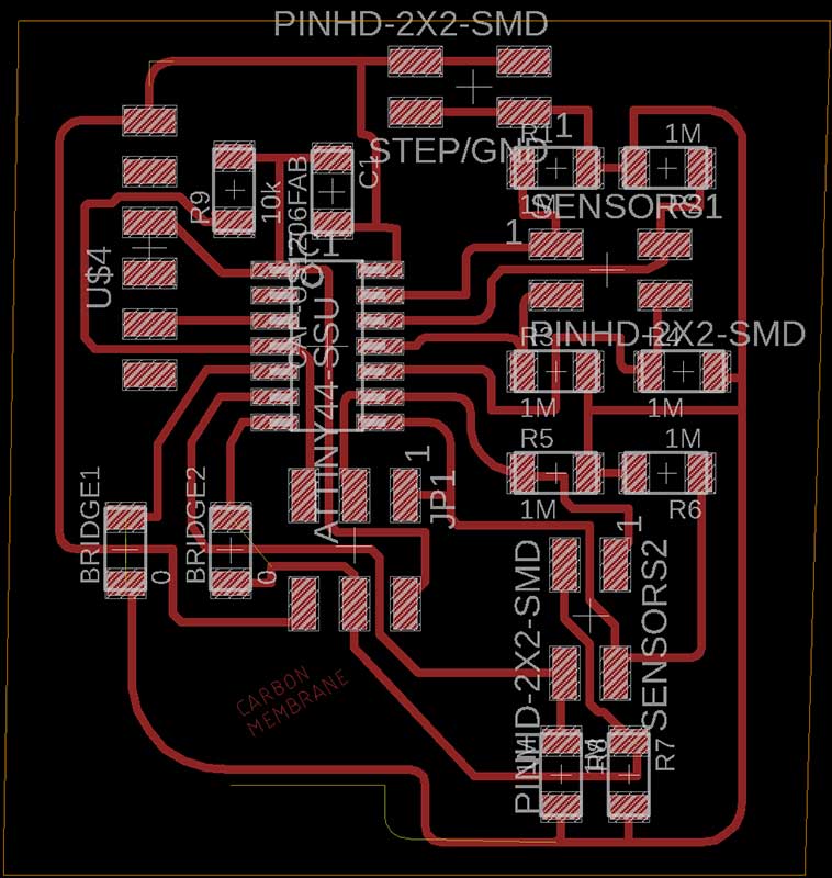
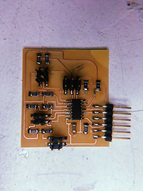 As you can see, I ended up placing two bridges on the board. I also wanted to have the words "Carbon Membrane" sketched out on my board. I added and sized the text in Eagle. For some reason, in my copy of Eagle the milling tolerance for text is higher. That is why I did not see any warnings and proceeded to generate the g-code in mods. When the milling ended, I realized that the letters had completely blended with each other which left the text non-readable. Besides those, I did not have any major issues milling or populating the board.
For this part of the assignment, I wanted to use the board I made during Week 11. I initially had designed that board for video and audio output. But for the purposes of the final project, I decided to use the same board to connect my LED strip. However as I was trying to program it, my voltage regulator burnt. I realized that I had confused the mosfet for the voltage regulator. This rendered my board unusuable.
My next option was to use the extra pin I had designed for my eighth sensor to connect the LED strip.
The UV light LED strip I needed a 9V power source which would burn the microchip. This can be fixed by using a "xxxxxx - voltage regulator" but this likely meant having to redesign my PCB. That is why I ended up using a Neopixel LED strip that I had bought for a different project. Neopixels have a couple of advantages over the first led strip I got in addition to the need of a 5V power source:
Neopixels are addressable. This means that each individual LED can be programmed to behave differently.
Neopixels are distributed by an established electronics company: Adafruit. Because of this, there is a lot of information, support and tutorials on their website.
Downsides: They depend on a microcontroller and they cannot emit real UV light.
pin 6
powered by the computer
no resistor and no capacitor.
< video of the strand test >
I then proceeded to trying to understand the code. My strip comes with the SK6812 LEDs. This means it runs a 800KHz bitstream (max frequency). It follows a GRB data structure instead of an RGB one.
I did some research on the different color temperatures that could be present both in fire and black light: Infrared, 2250K etc.
What could be the possible explanation for black body radiation?
Below is a pin-out diagram connecting the wiring of my board and my screen to the atmel and arduino nomenclature.
This is going to be invaluable information. 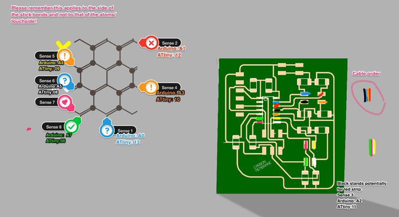
I based my code on Pilu Caballero's and proceeded as follows:
#include < avr/io.h > // Libraries previously installed
#include < util/delay.h >
#include < SoftwareSerial.h >

static uint16_t up, down;         // from Neil's Program
static uint16_t arriba, abajo;


SoftwareSerial mySerial(9, 5);


void setup() {
  pinMode(A2, OUTPUT); // Declaring the first sensor pin out from my board
  mySerial.begin(4800);
  //mySerial.println("Hello, world?");
}


void loop() {
  up = 0; // initial value for the states of sensor to up to 0
  down = 0; // initial value to 0 for down
  for (int count = 0; count < 100; ++count) {
    _delay_us(100);
    digitalWrite(A2, 1); //the pin out and his state
    arriba = analogRead(A3);
    up += arriba;
    _delay_us(100);
    digitalWrite(A2, 0);
    abajo = analogRead(A3);
    down += abajo;}


  arriba = 0;
  abajo = 0;
  arriba = analogRead(A4);
  _delay_us(100);


  if (arriba > 600) {
    mySerial.println(arriba);
  }


  _delay_ms(500);
}
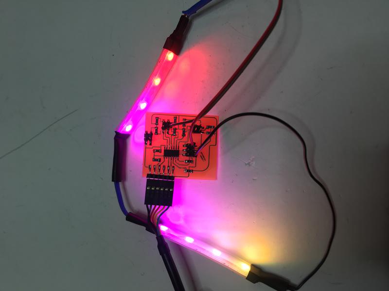
Because of the layout of the screen, I only ended up needing seven of the eight sensors. This meant that there was a pin where Sensor 3 was supposed to live that wasn't being used.
I then used that pin (corresponding to arduino Pin 8) as an Output pin. Note that using the Arduino Analogue pin numbering (in this case A5) did not work with the neopixels. I also replaced the 10 mega Ohms resistor for a 499Ohm resistor so as not to alter much the brightness of the led strip. Besides that, the code below worked fine.
        #include < Adafruit_NeoPixel.h >
  #ifdef __AVR__
    #include < avr/power.h >
  #endif
  #define PIN 8

  Adafruit_NeoPixel strip = Adafruit_NeoPixel(8, PIN, NEO_GRB + NEO_KHZ800);

  void setup() {

  pinMode(8, OUTPUT);
    strip.begin();
    strip.show();
  }

  void loop() {
    strip.setPixelColor(0, 255, 0, 0);
    strip.setPixelColor(1, 255, 0, 0);
    strip.setPixelColor(2, 255, 0, 51);
    strip.setPixelColor(3, 255, 0, 102);
    strip.setPixelColor(4, 255, 0, 153);
    strip.setPixelColor(5, 255, 51, 102);
    strip.setPixelColor(6, 255, 102, 51);
    strip.setPixelColor(7, 255, 153,0);
    strip.show();
  }
I based my design on this code by David Mccallum. Interface design was a big part of my final project. I started out by creating two different animations. The first one is what the user sees when she is not touching any of the sensor points: throbbing orange circles whose sizes vary randomly. I did so by including this snippet which indicates that sizes A1 and A2 are a random value comprised between 180 and 250 pixels.
  sizeA1 = random(180,250);

  sizeA2 = sizeA1;


  sizeB1 = random(110,180);

  sizeB2 = sizeB1;
When the users touch a contact point, I want the circles to move away from its predetermined position and move randomly.
  hor1 = hor1 - random(10,20);

  hor2 = hor2 + random(10,20);


  ver1= ver1 + random(10,20);

  ver2= ver2 - random(10,20);
 I then connected the two animations above by including them in an
 if...else statement and by linking my processing sketch to the arduino one. In the future, I would love to have the time to develop this animation further.
For more precise touch interactions, consider using both a touch and a pressure sensor.
Design a more elaborate animation on Processing. I want to do more tutorials and carry out my initial idea: animate and project one of the original photographs of the fire.
The stiffness of the PVC I used for the screen hinders the interaction with the user. In the future I woult like to use a more flexible material for the screen, maybe some type of silicone.
This zip file contains:
- Processing and Arduino Codes.
- Eagle Board and Schematics.
- Reviewed design of base support in stl.
- dxf and ai for laser cut arch and cover.
- svg and ai file for the screen.
- Fusion 360 render of the complete model.