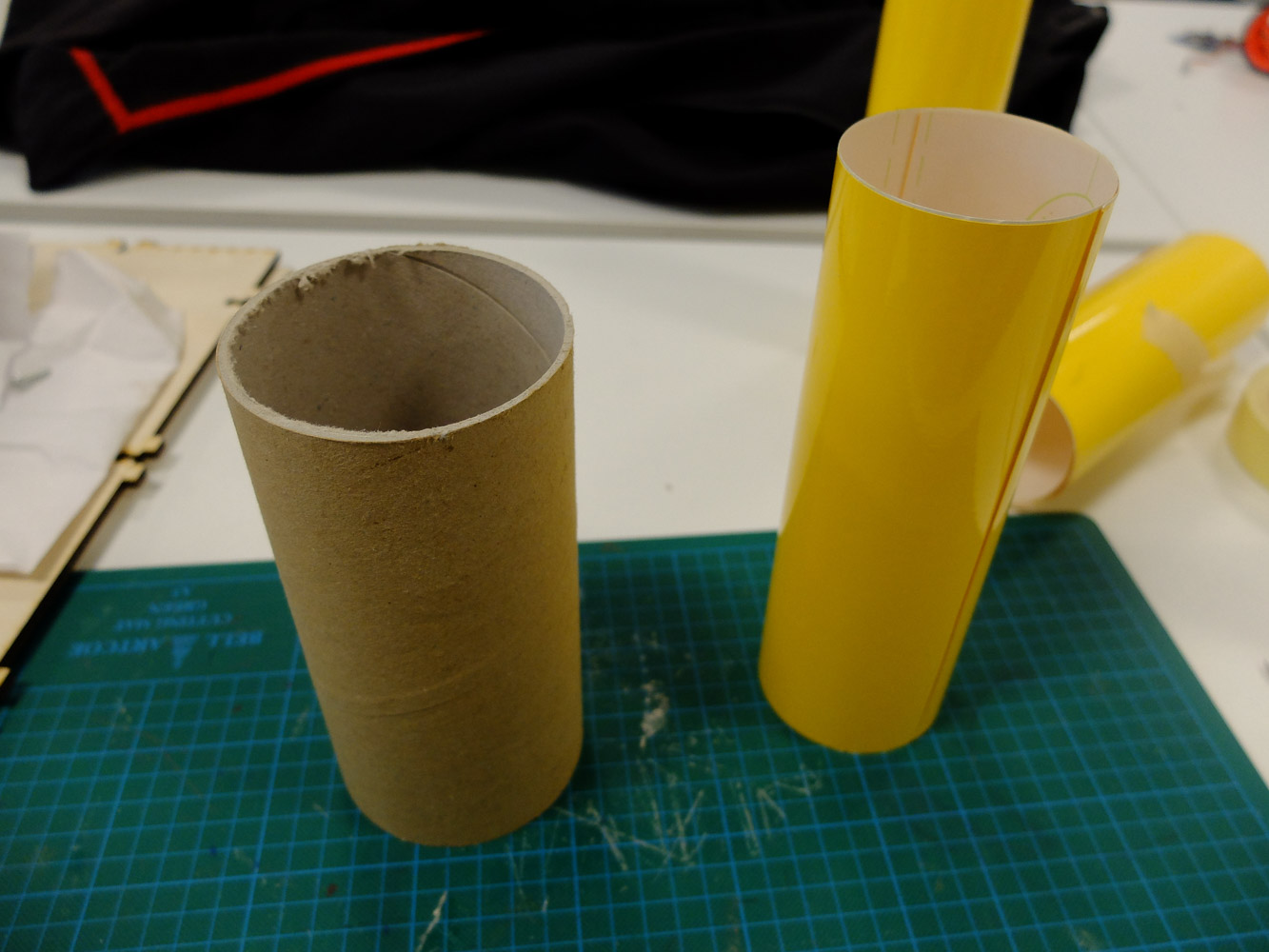
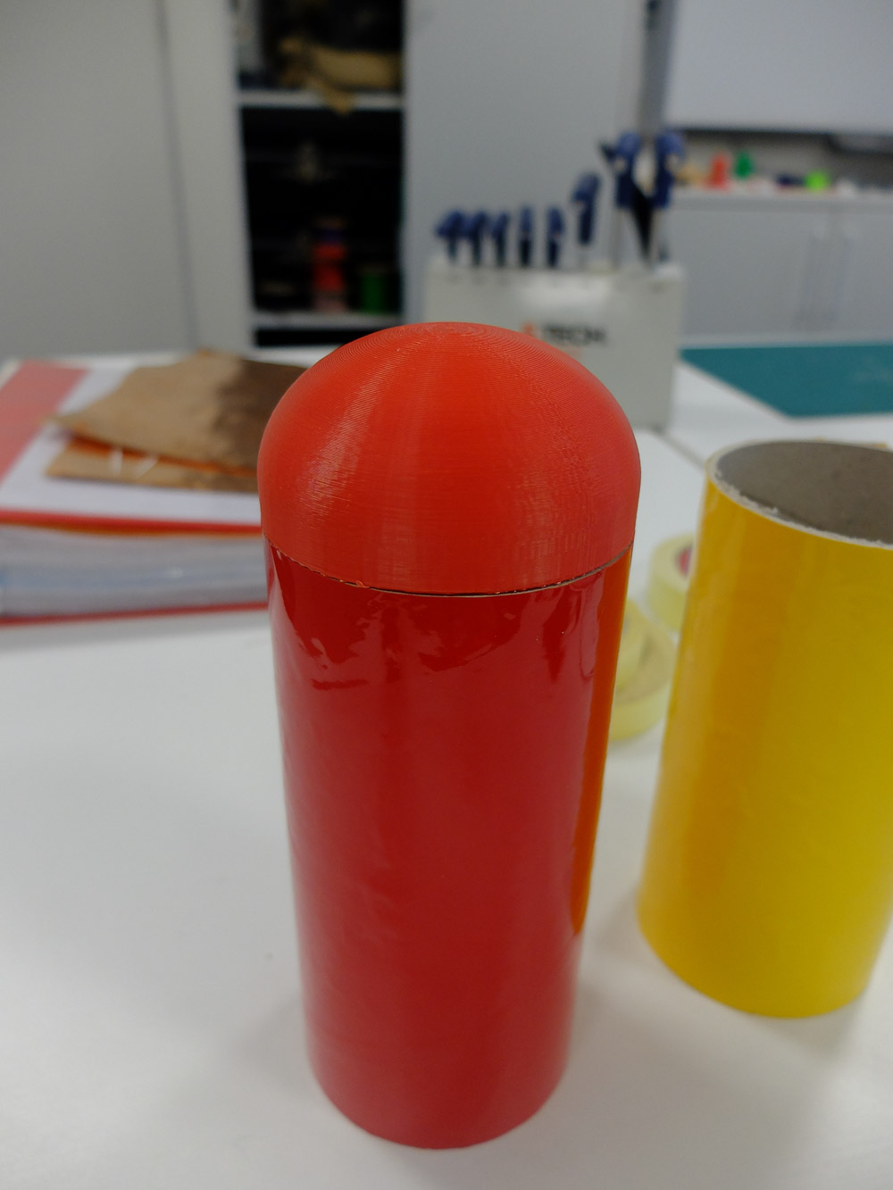
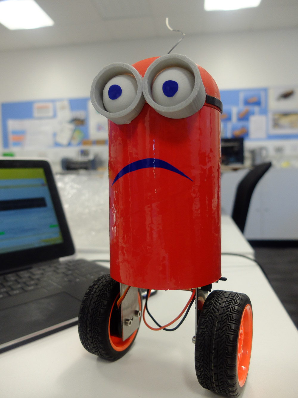
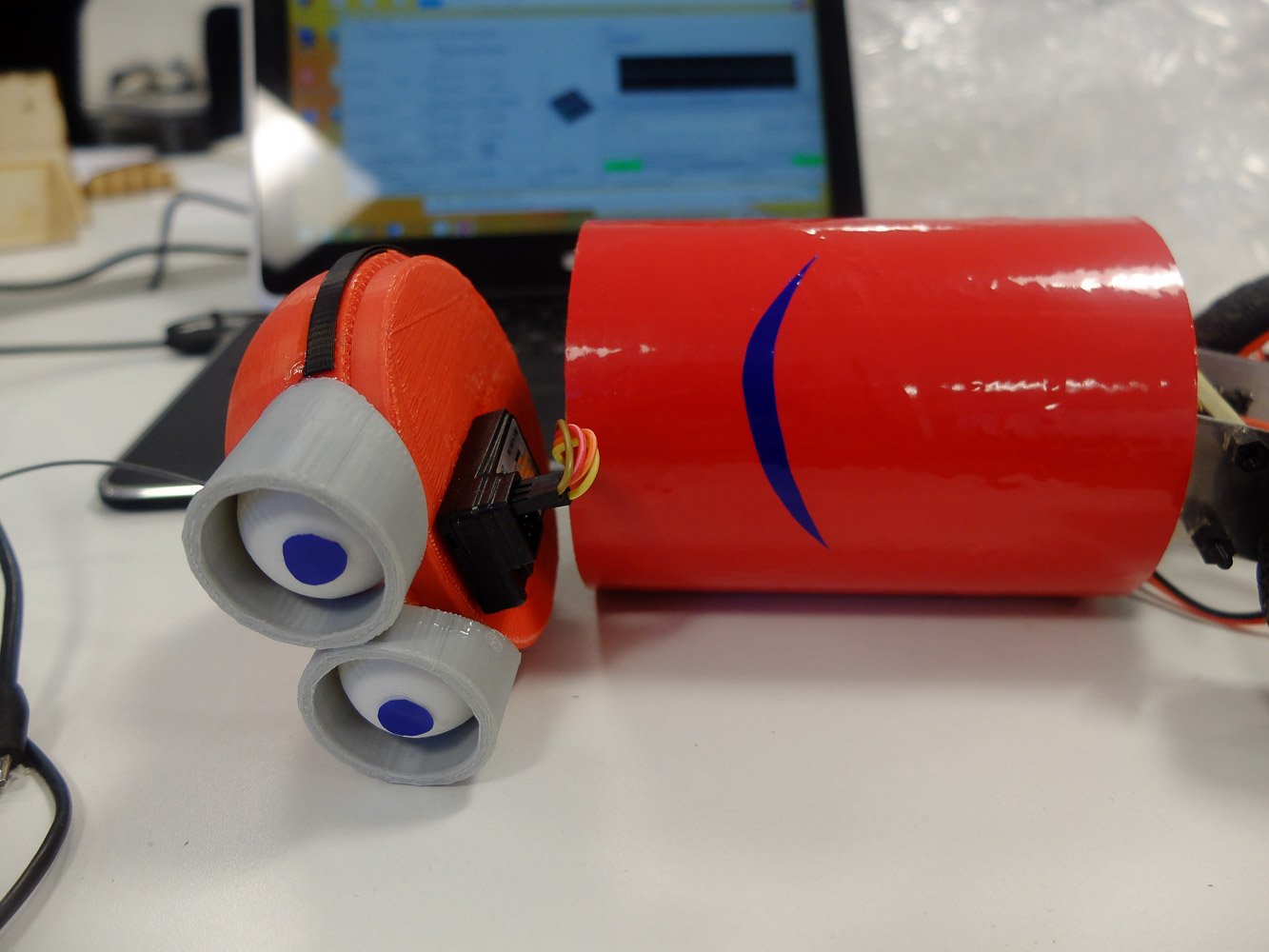
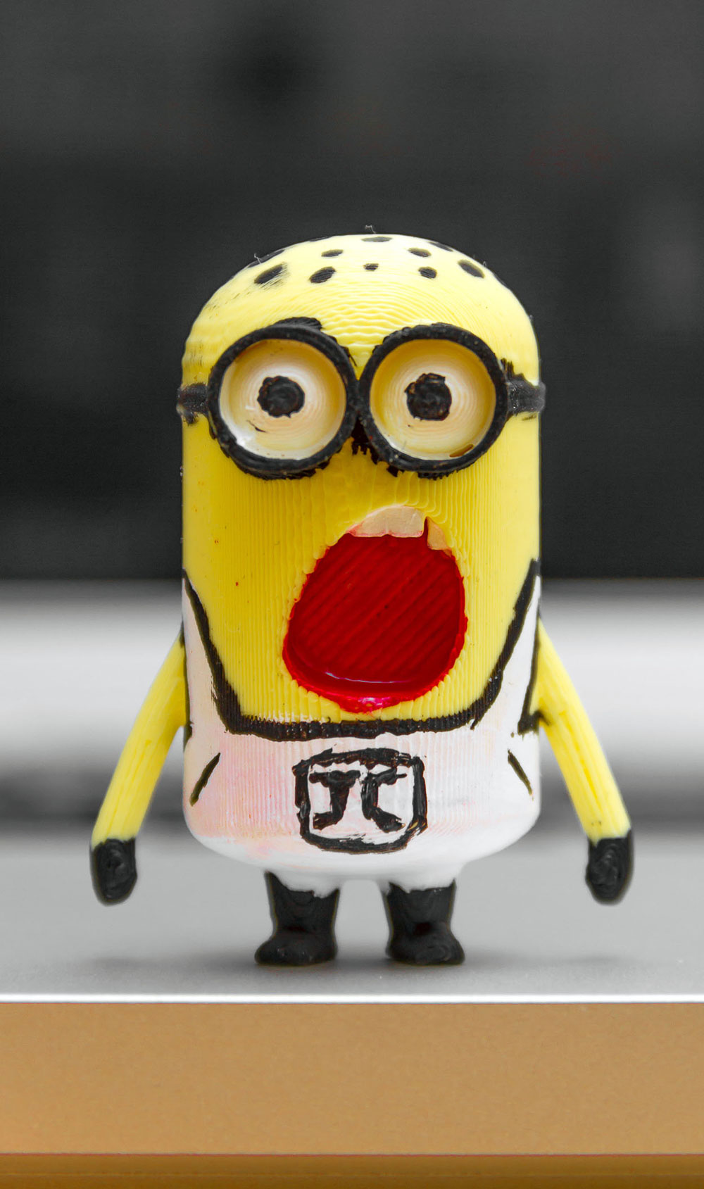
The body is made from a section of poster tube with vinyl on it. As a minion, it start with the most common yellow colour body until I realise that we run out of yellow ABS/PLA to match the colour.
So, i change it to my favourite colour, red.
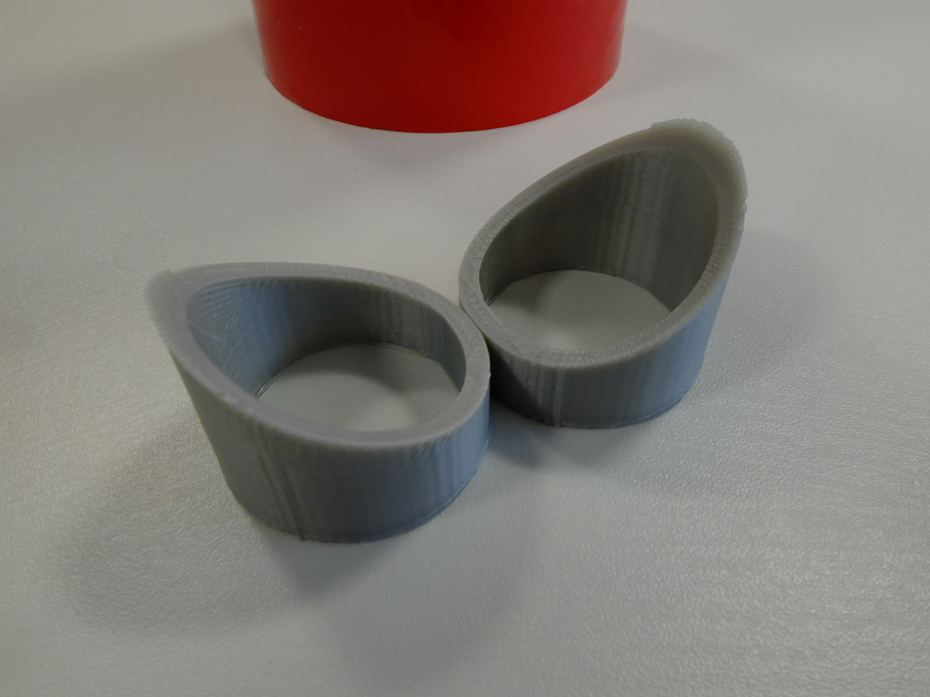
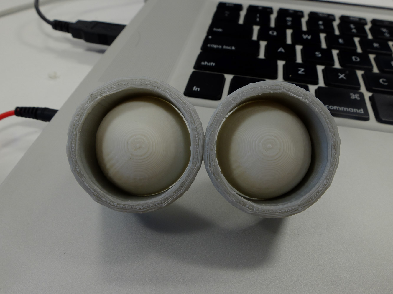
Glasses for minion
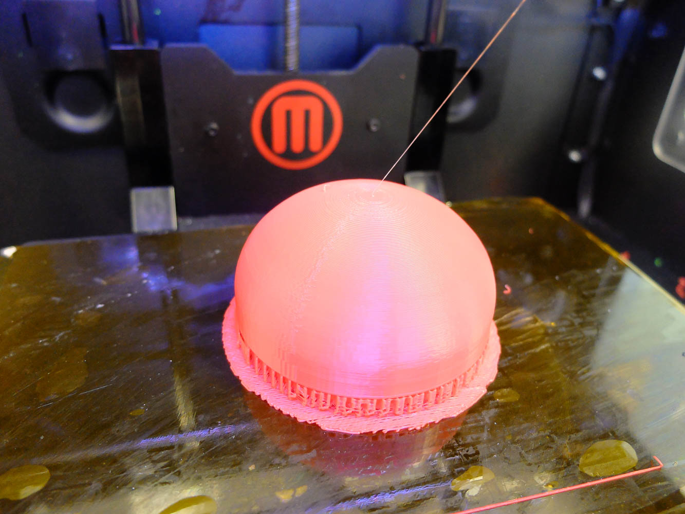
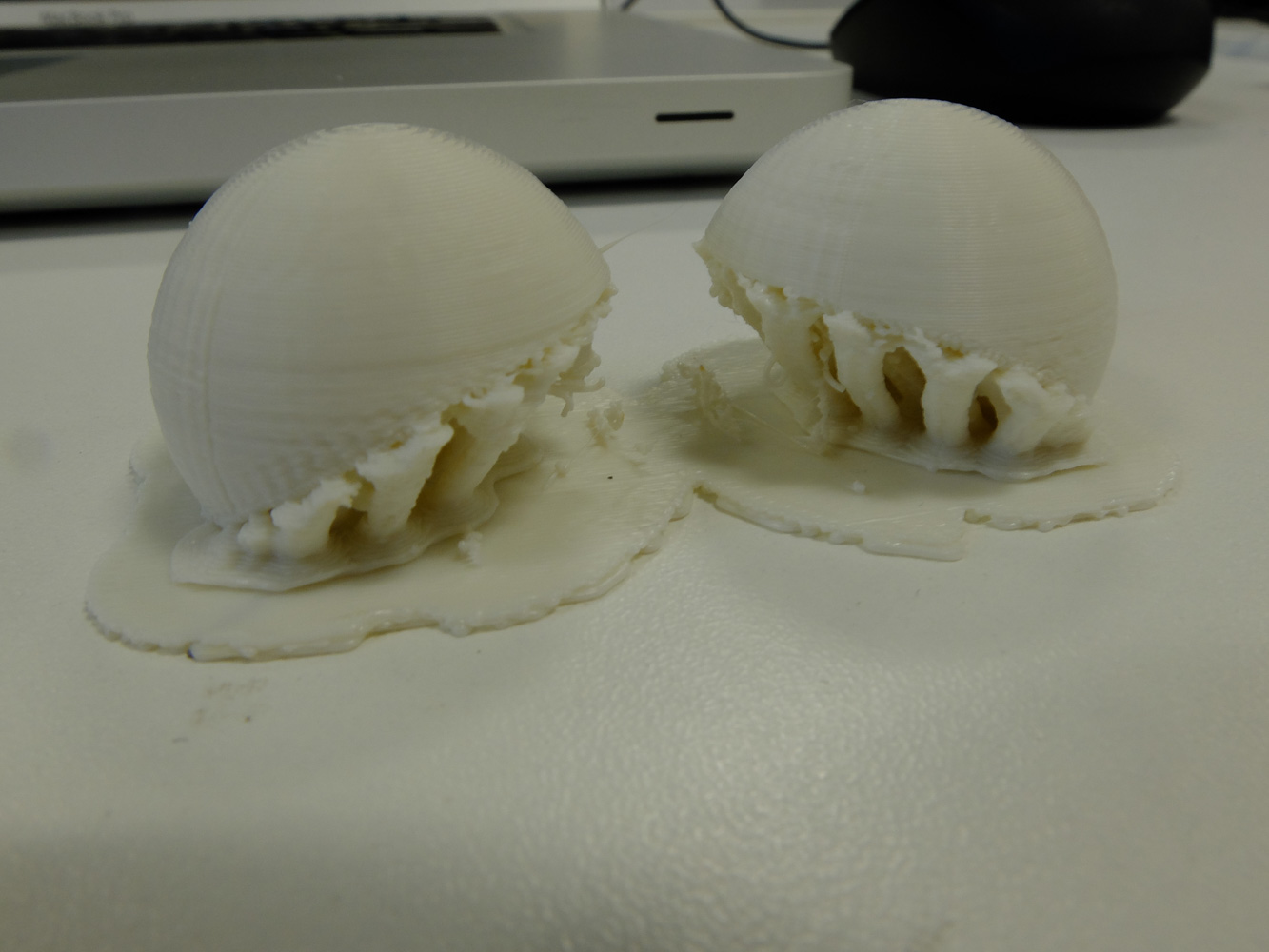
And eyeballs with support generated by meshmixer.
Finished eye assembly
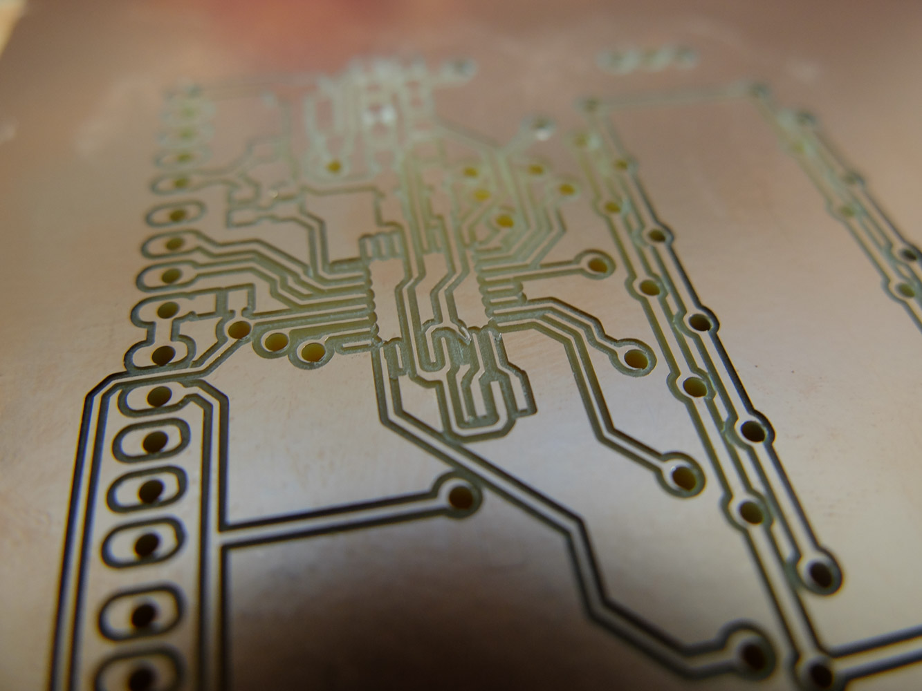
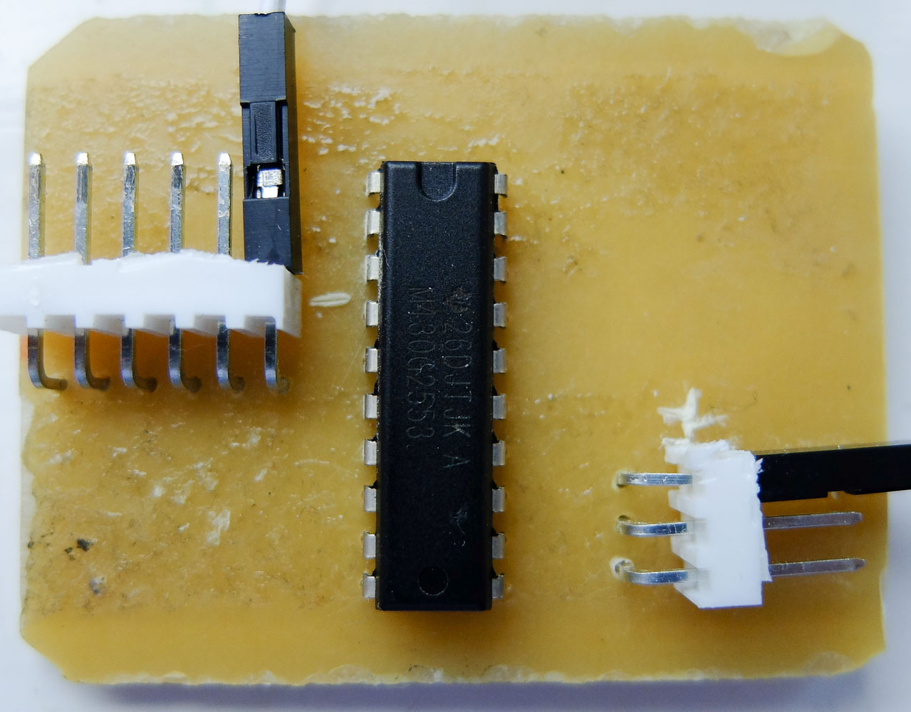
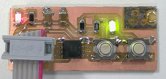
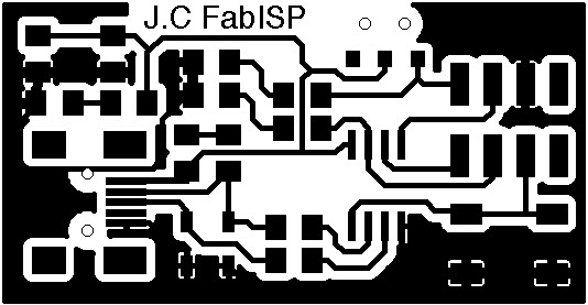
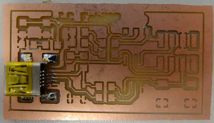
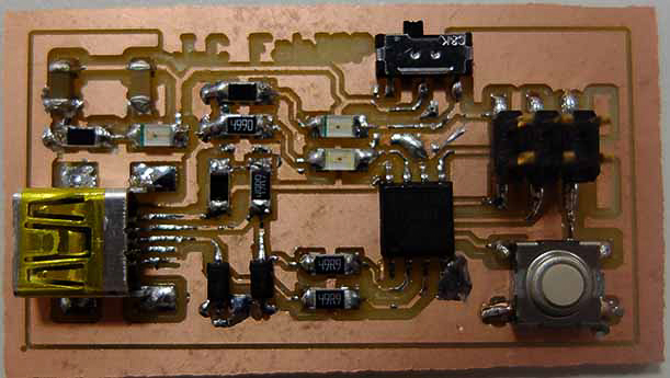
The heart of minion, the microcontroller and motor driver board. (with a fault on mcu pin, fixed by flywire)
A sad face due to countless fallen down during PID tuning
develop a plan for dissemination of your final project
License
For everything on this website, i would like to release them under ‘Creative Commons Attribution 4.0 International Public License’. This project was made for fab academy 2015 final project. Most of code are based on open source software and i have no plan for commerciallise. This project will remian open source.
Share — copy and redistribute the material in any medium or format
Adapt — remix, transform, and build upon the material for any purpose
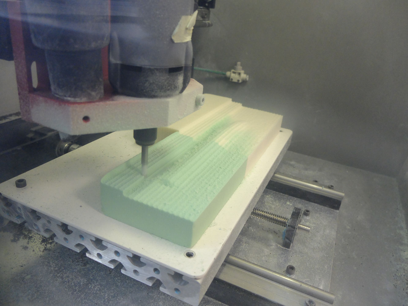
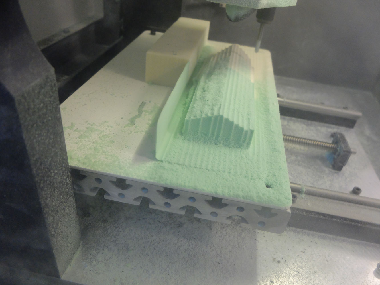
make a machine, including the end effector
build the passive parts and operate it manually
document the group project and your individual contribution
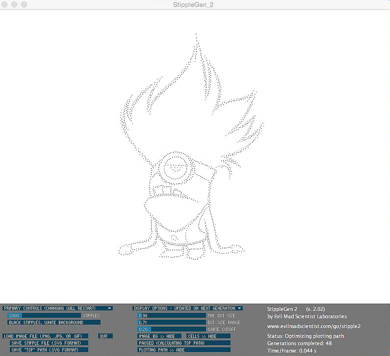
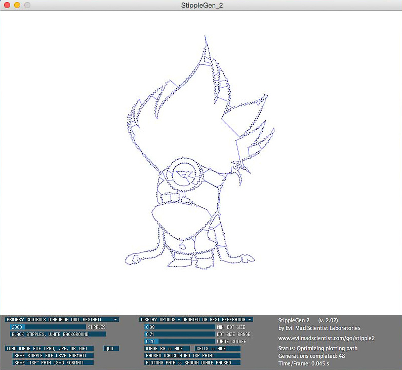
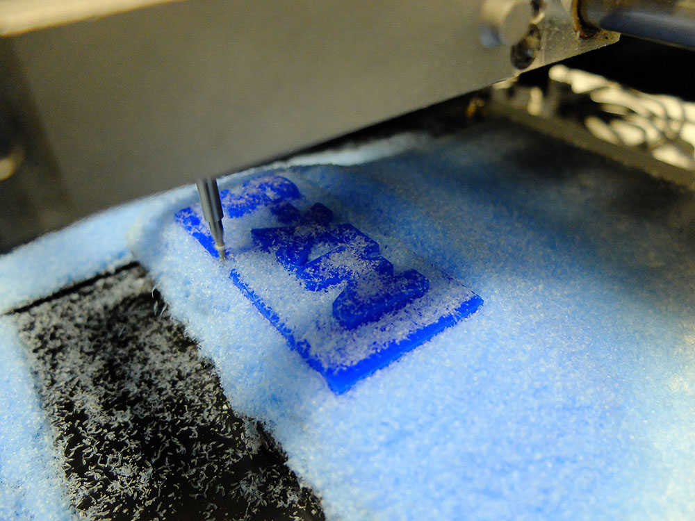
My main job is that find a way to convert pictures to files that could be read by our drawing machine.
Start with software called ‘StippleGen_2’ to generate .svg file for next step. It solves the classic traveling sales man problem that is almost exactlly what we want.
Then the .svg file is converted to both python code and .csv for drawing machine by the following matlab code.
functioncsv_gen(file_name,maximum_size)%file_name='evil_minion'; maximum_size=200;%read svg to text[data,result]=readtext(sprintf('%s.svg',file_name),' ');%read coordinates from textm=1;forn=1:result.rowsifisnumeric(cell2mat(data(n,1)))&~isempty(cell2mat(data(n,1)))ifisnumeric(cell2mat(data(n,2)))&~isempty(cell2mat(data(n,2)))coor(m,1)=cell2mat(data(n,1));coor(m,2)=cell2mat(data(n,2));m=m+1;endendendmin_coor=min(coor);forn=1:length(coor)coor_shifted(n,:)=coor(n,:)-min_coor;end%re-scale to 200mm sizecoor_a=coor_shifted*maximum_size/(max(max(coor_shifted)));% %convert to relative coordinates% coor_r=coor_a(1,:);% for n=2:length(coor_a)% coor_r(n,:)=coor_a(n,:)-coor_a(n-1,:);% end%generate .csv filecsvwrite(sprintf('%s.csv',file_name),coor_a);%csvwrite(sprintf('%s_r.csv',file_name),coor_r);%generate python code in .txtfid=fopen(sprintf('%s.txt',file_name),'wt');fprintf(fid,'moves = [');fprintf(fid,'[%d,%d]',coor_a(1,1),coor_a(1,2));forn=2:length(coor_a)fprintf(fid,',[%d,%d]',coor_a(n,1),coor_a(n,2));endfprintf(fid,']');fclose(fid);% fid = fopen(sprintf('%s_r.txt',file_name),'wt'); % fprintf(fid,'moves = [');% fprintf(fid,'[%d,%d]',coor_r(1,1),coor_r(1,2));% for n=2:length(coor_a)% fprintf(fid,',[%d,%d]',coor_r(n,1),coor_r(n,2));% end% fprintf(fid,']');% fclose(fid);plot(coor_a);
Due to the budget limit which i didn’t realised at the very beginning. I have decide to make a new ‘fab academy’ version of my old balanced robot prototype.
propose a final project that integrates the range of units covered:
  what will it do?

  	Self balance, remote controlled minion

  who's done what beforehand?

  	Errr..almost everything. There are tons of balanced robot design online availiable already. The unique feature of this one is the BLDC motors. And it is pretty similar as the brushless gimbal.

  what materials and components will be required?

  	Still..almost everything. 3d printed body, brushless motor, wheel, etc..

  where will they come from?

  	My electronic 'magic' box and old projects

  how much will it cost?

  	BLDC motor £8 each

  	the rest could be sourced from fablab or my old projects

  what processes will be used?

  	Atmega328p

  what tasks need to be completed?

  	Modify gimbal controller board software, PID tunning

  how will it be evaluated?

  	Self balance stand would be a good point to start with.
write an application that interfaces with an input &/or output device
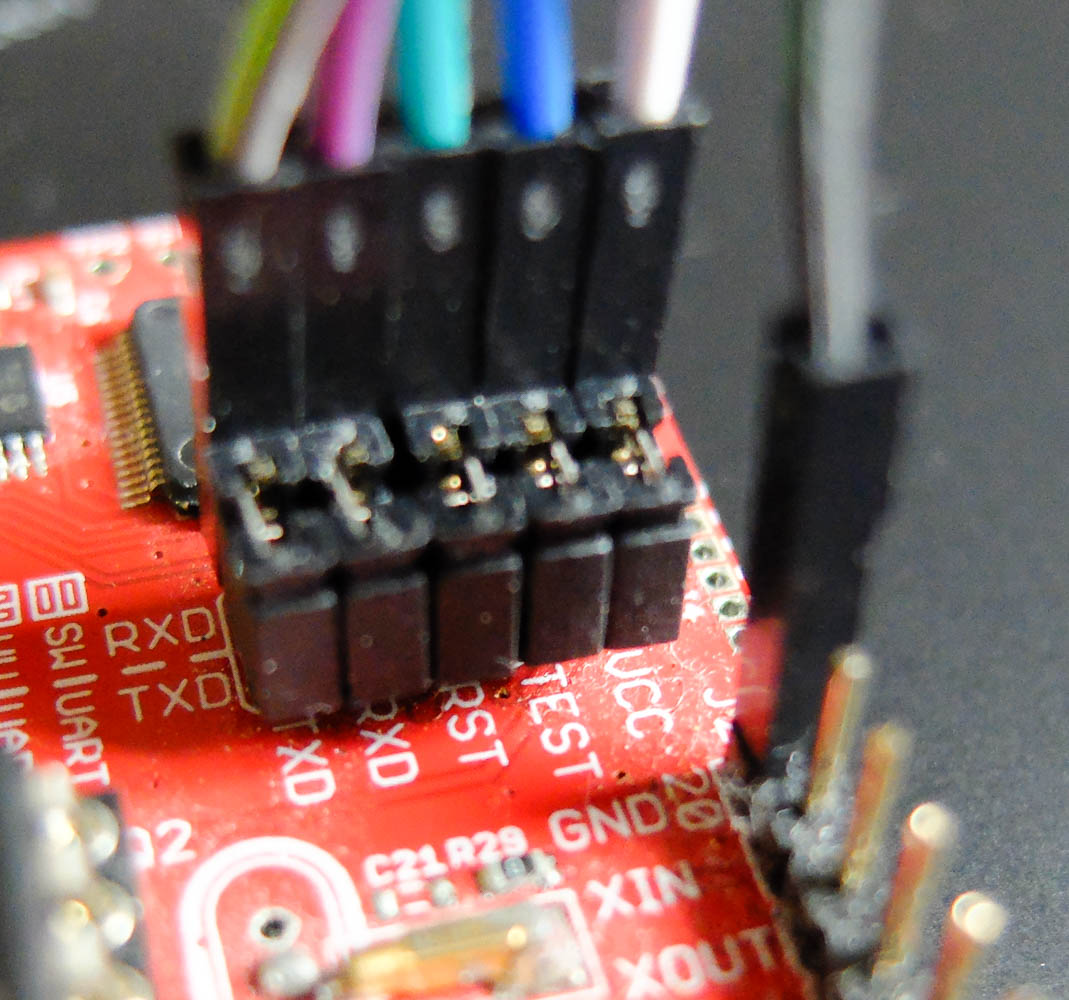
A very simple board is created with msp430g2553 and programed with Energia.
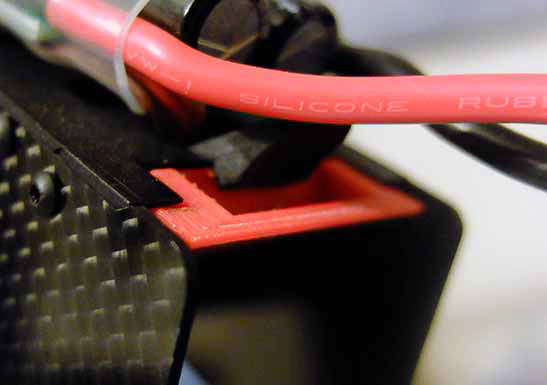
Mini USB connector is for power only.
Jumper wires from TI Launchpad
The board is connect to a bluetooth module (HC-05) via serial port.
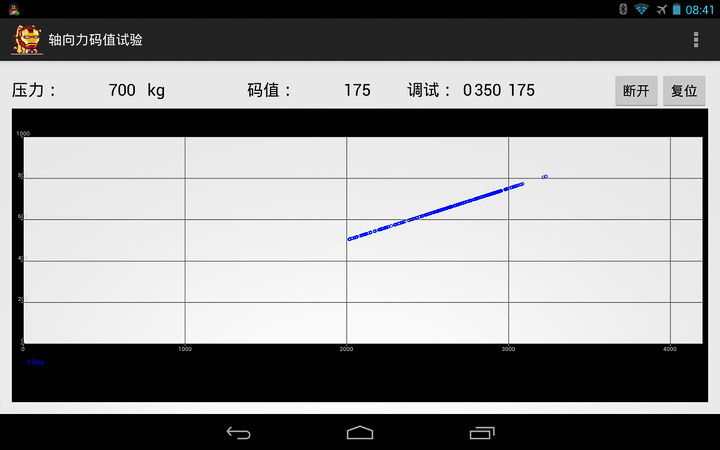
An android app was created to receive data via bluetooth and plot them in real time.
(This app is created as a favour to my friend, thus the interface is in chinese.)
add an output device to a microcontroller board you've designed and program it to do something
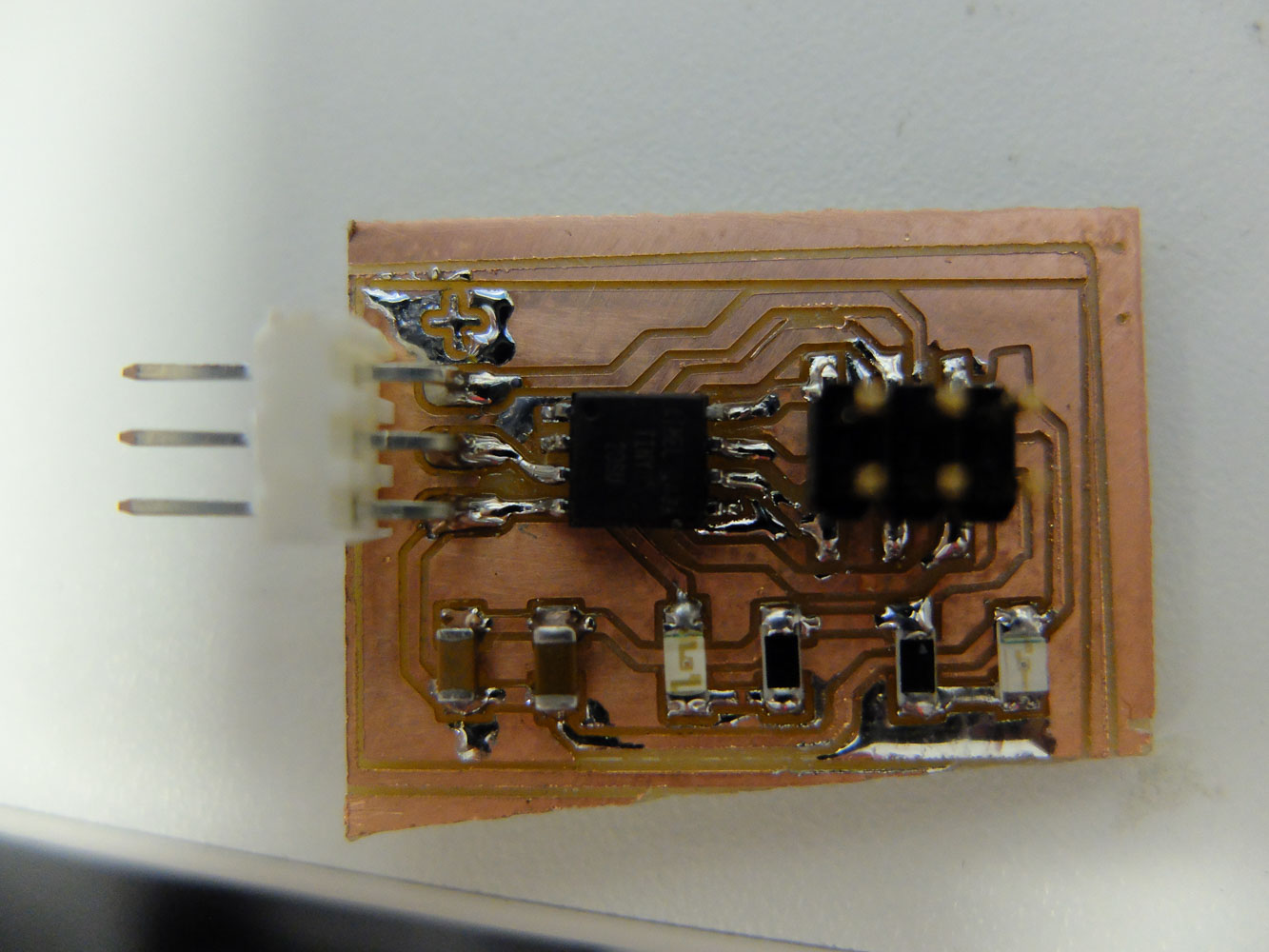
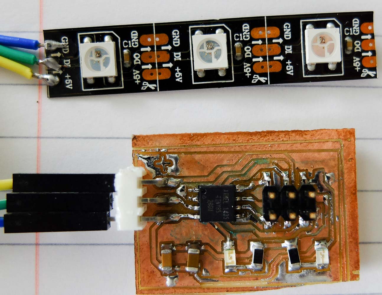
A very simple board that designed to control WS2812 RGB LEDs.
Code
#include <Adafruit_NeoPixel.h>
#include <avr/power.h>
#define PIN 4
#define NUMPIXELS 3
Adafruit_NeoPixelpixels=Adafruit_NeoPixel(NUMPIXELS,PIN,NEO_GRB+NEO_KHZ800);intdelayval=50;// delay for half a second
intindex=0;intlast_index=0;intlast_last_index=0;charorder=0;voidsetup(){// This is for Trinket 5V 16MHz, you can remove these three lines if you are not using a Trinket
#if defined (__AVR_ATtiny85__)
if(F_CPU==16000000)clock_prescale_set(clock_div_1);#endif
// End of trinket special code
pixels.begin();// This initializes the NeoPixel library.
}voidloop(){pixels.setPixelColor(last_last_index,pixels.Color(0,0,0));last_last_index=last_index;pixels.setPixelColor(last_index,pixels.Color(20,0,0));last_index=index;if(order){pixels.setPixelColor(index,pixels.Color(50,0,0));index++;if(index>=(NUMPIXELS-1)){order=0;}}else{pixels.setPixelColor(index,pixels.Color(100,0,0));index--;if(index<=0){order=1;}}pixels.show();delay(delayval);}
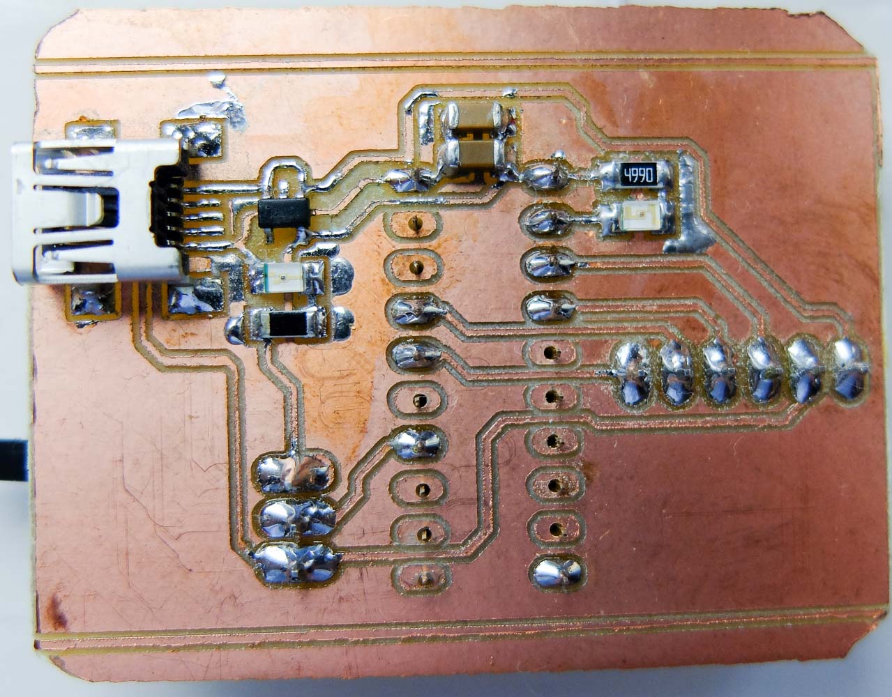
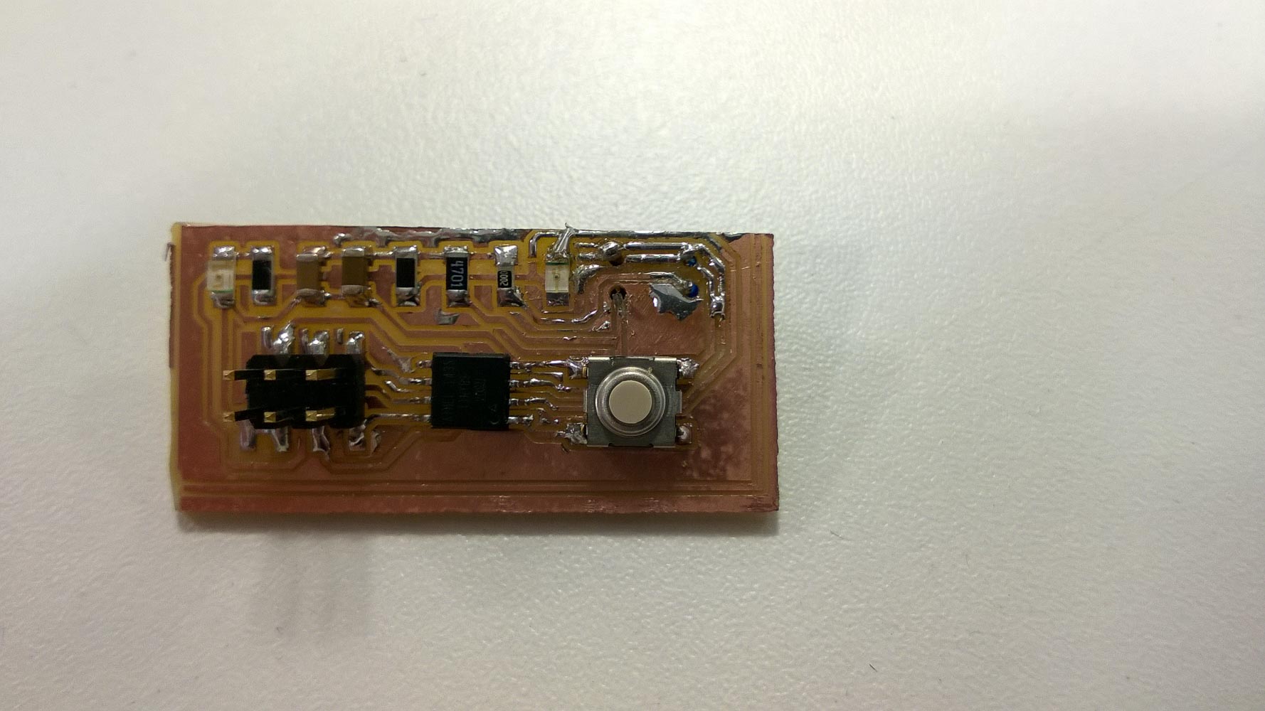
measure something: add a sensor to a microcontroller board that you've designed and read it
TCRT 5000 is a reflective optical sensor with transistor that typically used by line followers. It is a simple analog sensor.
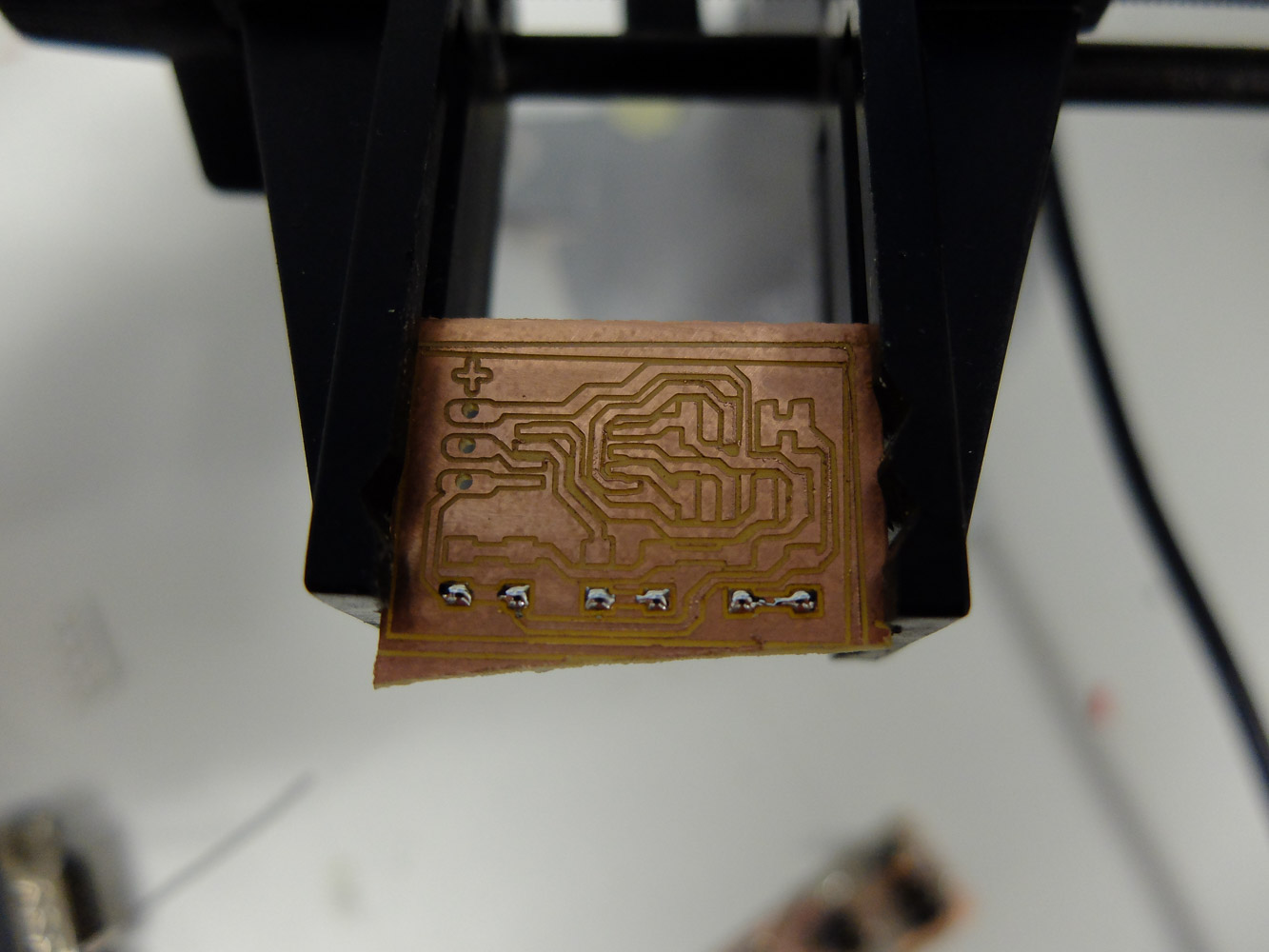
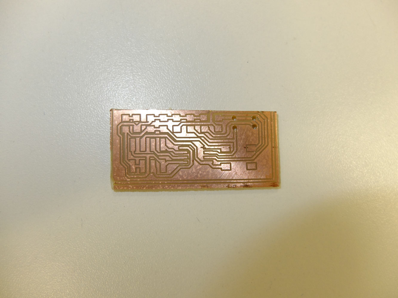
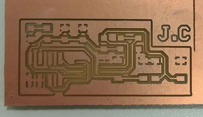
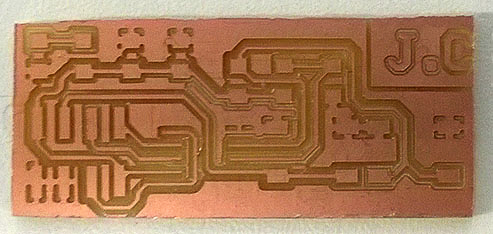
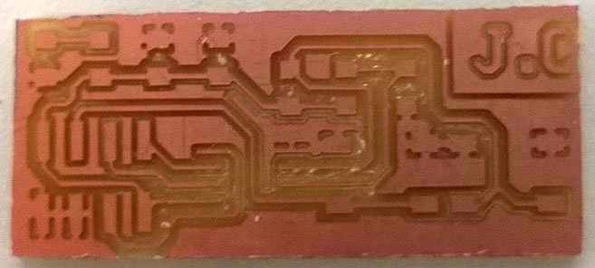
PCB
Top View
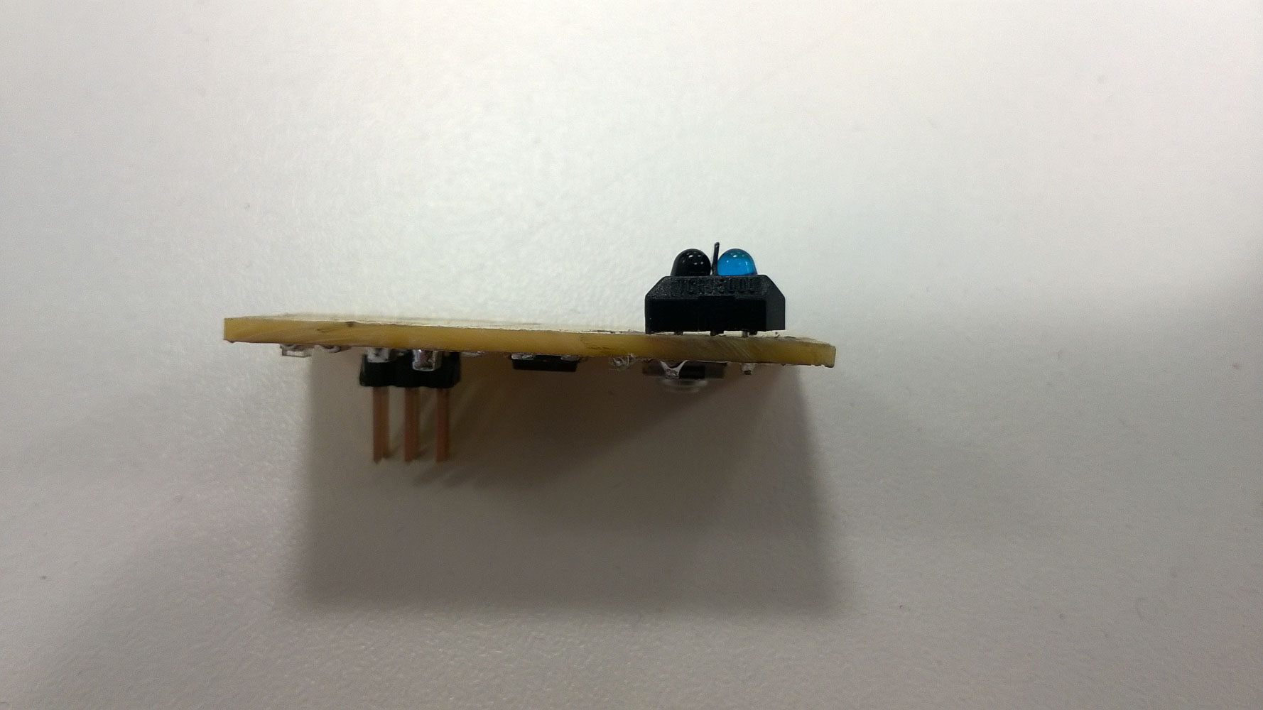
Side View
The LED with flashing in different speed according to the input.
Code
#define LED 3
#define IR A2
intadc=0;voidsetup(){pinMode(LED,OUTPUT);}voidloop(){digitalWrite(LED,HIGH);adc=analogRead(IR);delay(adc);digitalWrite(LED,LOW);delay(256-adc);}
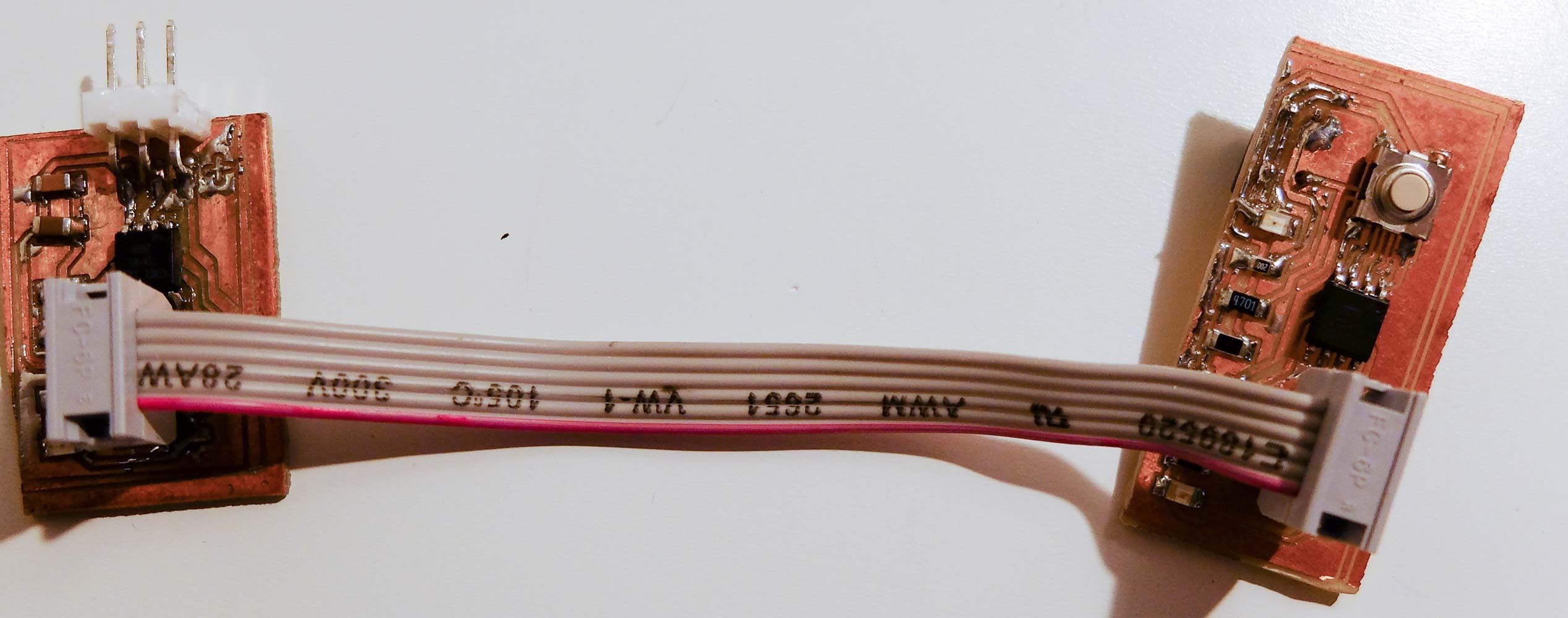
read a microcontroller data sheet
program your board to do something,
with as many different programming languages and programming environments as possible
Code
This code is based on arduino firmware. Press the button to increase the brightness of LED.
#define LED 3
#define BUTTON 4
intbrightness=0;voidsetup(){pinMode(LED,OUTPUT);pinMode(BUTTON,INPUT);}voidloop(){analogWrite(LED,brightness);if(digitalRead(BUTTON)){brightness++;}if(brightness>255){brightness=0;}delay(10);}
redraw the echo hello-world board
add (at least) a button and LED (with current-limiting resistor)
check the design rules, and make it
extra credit: simulate its operation
Result
This assigment is basicly covered by the fabisp week. But i do got a new ‘hello-world’ board redesigned.
PCB
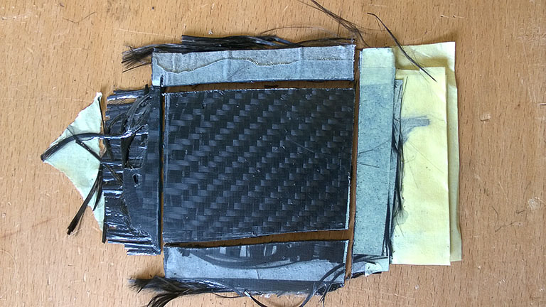
Knife cleaned PCB
Completed ‘Hello World’ board
#define LED 3
#define BUTTON 4
voidsetup(){pinMode(LED,OUTPUT);pinMode(BUTTON,INPUT);}voidloop(){if(digitalRead(BUTTON)){digitalWrite(LED,HIGH);}else{digitalWrite(LED,LOW);}delay(100);}
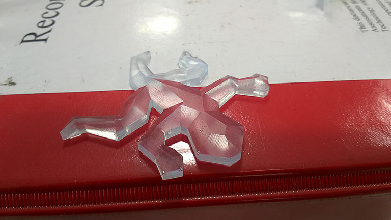
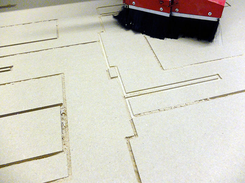
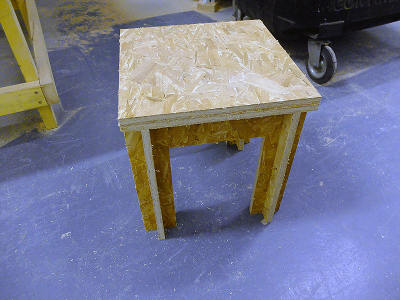
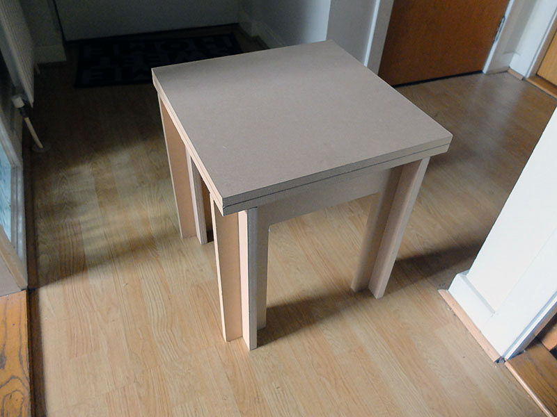
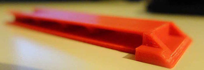
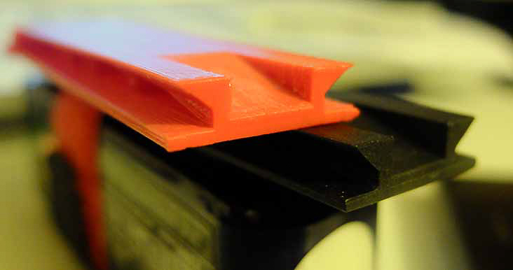
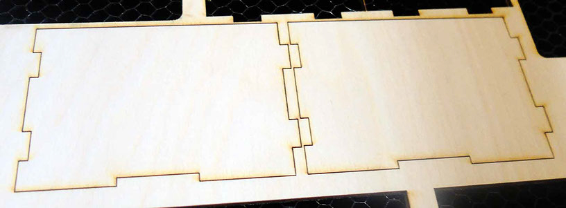
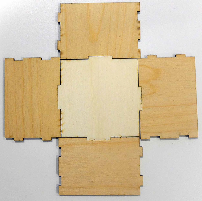
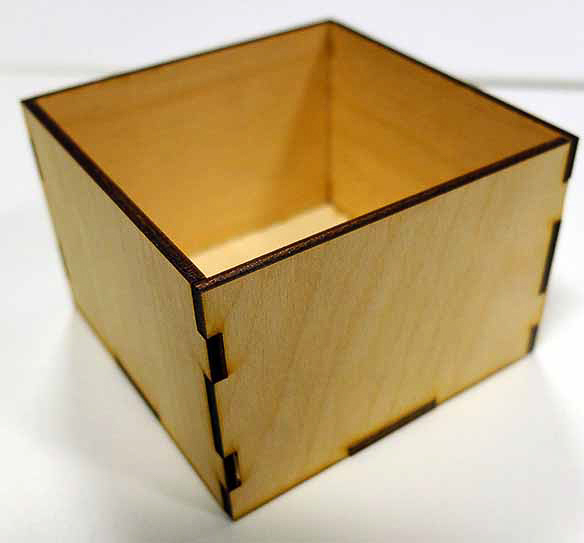
design, make, and document a press-fit construction kit!
And here it is!
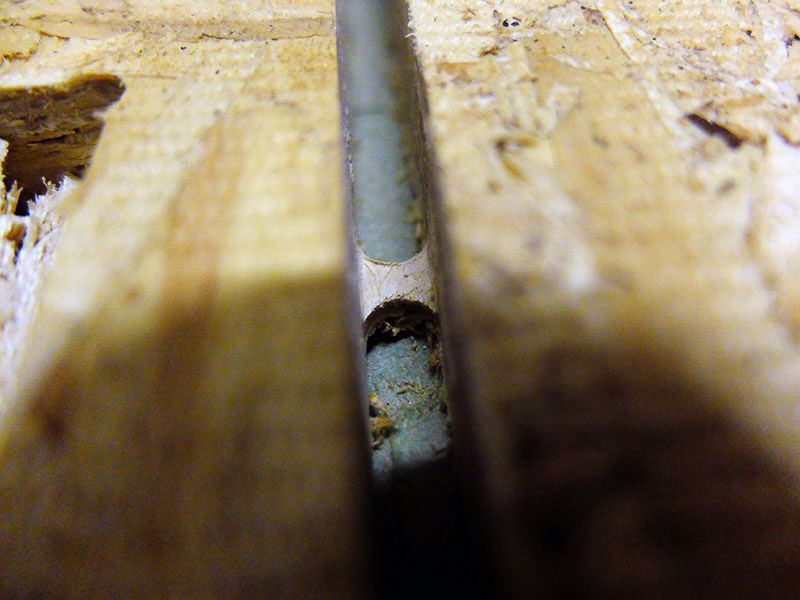
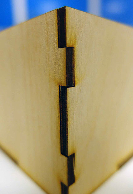
The design is a very straight forward press-fit box without lid. The press-fit part has a 0.3mm overlap for tight fit.
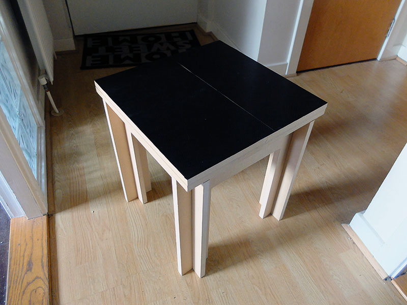
The laser cutter used in this project is Epllog 40 which is a 40W CO2 laser. I use the following setting to vector cut the 3mm board.
Speed: 10
Power: 100
Frequency: 500
Miata Is Always The Answer!!
Even for late added vinyl cutting task.
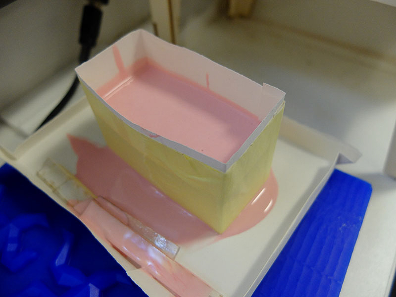
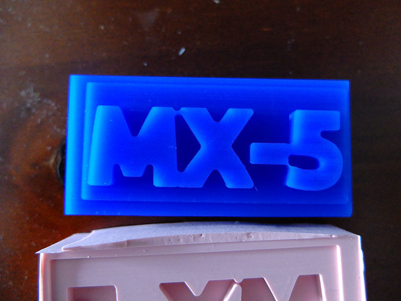
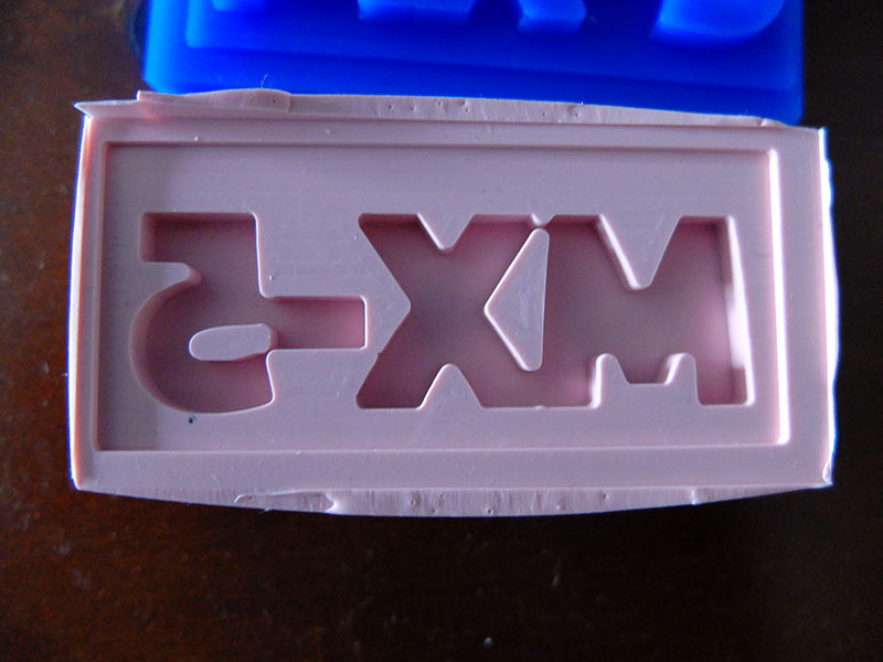
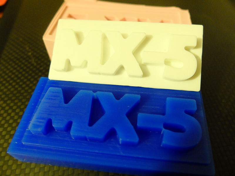
Here are the vinyl cutted logo for the 25th anniversary of the world best selling roadster, Mazda MX-5 or Miata for US.
The vinyl cutter used in this project is Roland GX24 with all default settings.
Get the files
You can download the source files for press-fit box directly.
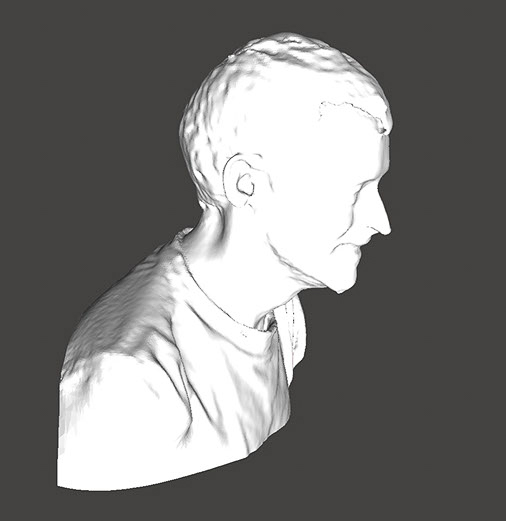
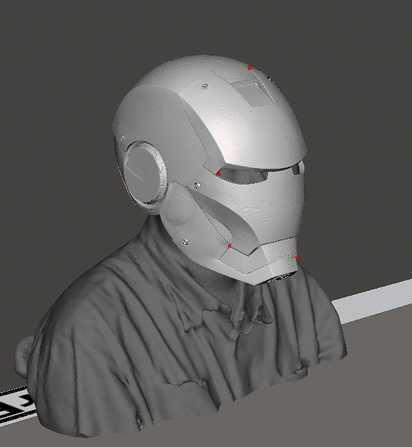
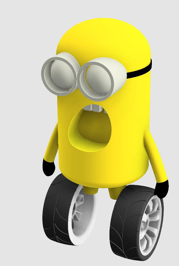
model (draw, render, animate, simulate, …) a possible final project, and post it on your class page
Basically, it is a remote controlled balanced robot. All the fancy part of this final project are well hidden in the software.
But, It does have a very lovely body to post.
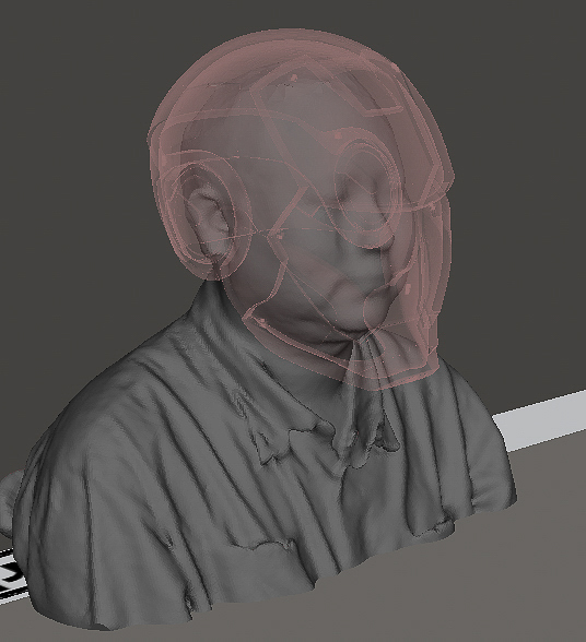
The model is for demostration only. The body is made by a section of tube and the head is 3D printed which documented in the page of final project update 3.
Get the files
You can download the source files for press-fit box directly.
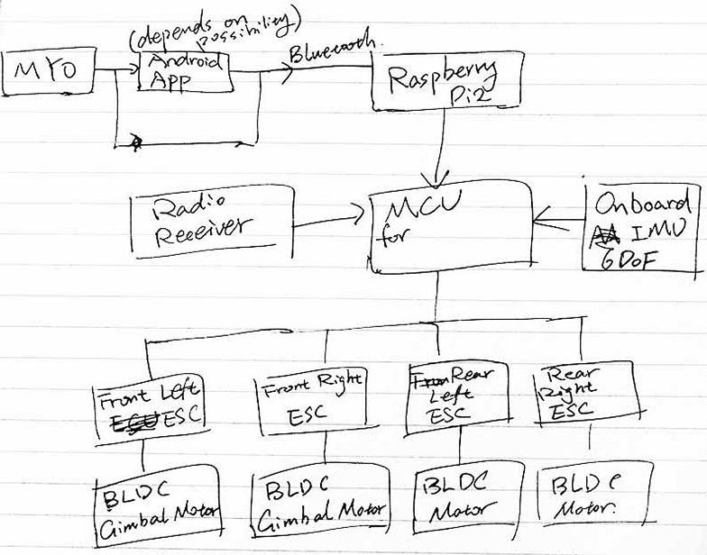
My current plan for final project is a MYO controlled 4WD car. And it would allow conventional radio control for more fun.
The rear wheels are driven by BLDC motors directly for a higher top speed. The electronic speed controller (ESC) for them are specially design multicopter ESCs with reverse direction supported.
The front wheels would be driven by special BLDC motors designed for gimbals. This motor features high torque which is necessary for start. The front wheels and motors are connected via a single direction bearing to reduce the drag after start.
Therefore, the car is front wheel drive during the start and rear wheel drive after start.
A on-board 6DOF inertial measurement unit (IMU) is used for stability and traction control, apply the break to each wheel when necessary.
All wheel would be fitted with a simple push-rod suspension for better handling.
Overall, this would be a miniature version of modern hypercars, with a lot of fancy electronic systems.
A simple block diagram show below. (which i forgot to add the steering after MCU)