Electronics Design
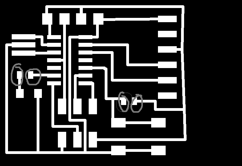
This week we learned about electronics design. We were tasked with taking an existing electronic circuit board design, adding some components, and then fabricating the design. The board starts as a design in a program called Eagle. Eagle is an electronics design program that is available in a free version. The program uses two different views of the board you are designing, with a schematic view and a board layout view. First, I added the necessary components in the schematic view, then switched to the layout view to place the components on the board. After this, I exported the layout view as a picture. Then I edited the picture in photoshop and made the size of the image a little but bigger. I created a new instance of the file, added a white border, and filled in the white traces. I brought these files to the modela, and milled out thr traces, and then used the other file to cut out the board.
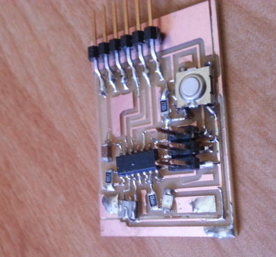
I thought Eagle was pretty intuitive, and didnt have much trouble understanding it and figuring out how to make chages to the board. However, when I milled out the board, I realized that I had used the wrong size of resistor in Eagle, which made the pad spacing on the board too small. I was lucky enougth to be able to use the larger resisitors, and just solder the resistors to the traces.
I soldered the resistors on first, and after I was able to get those on succesfully, I soldered on the rest of the components. I have some previuos experience soldering, so it wasn't too tough to get the parts on. I plugged it in to the computer to "smoke test" it, and nothing happend, which was a good thing. Stay tuned for programing!

