Final Project
For my final project I designed and built a weather station for my room. I like the look of the dial style of gauge, so I used servos to replicate this look. It uses a fabricated arduino clone as the brain, and is housed in a laser cut case. There are 3 sensors that go on the top of the roof; a thermometer, a light sensor, and a humidity sensor. 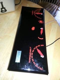
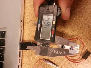
To start off the project, I designed the electronics. I first used what I learned in the input devices week to hook up my thermometer to my fabricated arduino. Next I tested the concept by hooking up a servo to the arduino. It was a simple task, all I had to do was hook up a power and groud wires, and then attach the signal wire to one of the pins of the arduino. I learned how to use a servo from the adafruit tutorial on the topic. I then used the servo write command to use the input recieved from the thermometer to move the servo to the desired position. To get the servo to work correctly, I had to take the range of the servo- 180 degrees, and transform it into the 110 degree range that I wanted to display from the thermometer. Because the range I wanted to use had negatives, I had to convert the temperature to kelvin first so that I could then multiply it to make it use the full range of the servo. This worked, but the servo spun the opposite way I wanted. To correct this, I used a little math to make it work. I ended up using 180-((kelvin - 249) * 2.9) as my formula.

Next I hooked up the light sensor. I used a photocell for this purpose, as they are relativly accurate and inexpensive. I learned how to hook up and use the sensor from the adafruit tutorial on this topic as well. The sensor outputs between 0 and 1023, so I had to make this work with the 180 degrees of rotation that the servo has. I decied to use sequential if statements to make this work, as I wanted it to have steps, rather than a gradual range. I experimented a little and ended up with a section of code that looked like this:
photocellReading = analogRead(photocellPin);
if (photocellReading < 200) {
myservo8.write(180);
delay(500);
} else if (photocellReading < 300) {
myservo8.write(144);
delay(500);
} else if (photocellReading < 600) {
myservo8.write(108);
delay(500);
} else if (photocellReading < 900) {
myservo8.write(72);
delay(500);
} else {
myservo8.write(36);
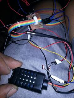
Next I hooked up my humidity sensor. This sensor also only required a ground, power and signal wire from the arduino. Again, I learned how to hook up and use the sensor from the adafruit page. This sensor has a thermometer as well, but the ONEWIRE model is more accurate and is waterproof, so I am only using the humidty data from this sensor. I again had the problem of making the range of the sensor match up with the range of the servo. my command for this ended up being: myservo9.write(180 - (h * 1.8));
(h is the humidity reading from the sensor)
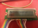
Next, I hooked up my LCD screen to the arduino exaxctly how I hooked it up when I used it to complete the output devices section. I used the lcd.write command to send the exact temperature and humidity to the screen.
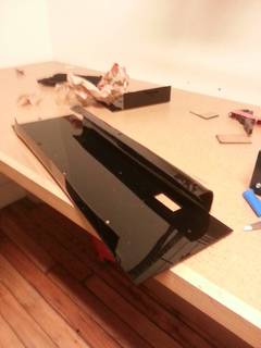
After I got the electronic system working, I Worked on making it look pretty. I laser cut the dials that fit on the ends of the servos from red acrylic. Then I laser cut the actual housing. I measured the servos, and made the holes on the housing hold the servo bodies by a presure fit. I did the design work in inkscape. I cut the housing out, and then used our acrylic bender, and a heat gun to bend the acrylic into the shape of an open backed box with holes to mount on the wall.
I cut red vinyl lettering to match the red dials to make the turning dials mean something. I put the vinyl on the front of the box, and then taped the lcd to the back of the box and and taped it into place.
Downloads:

