 Final Project
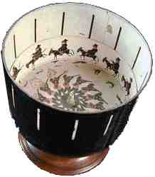
3D Zoetrope
Summary and Materials

Summary
My, I am very happy to say, successful plan was to produce a 3D Zoetrope using skills learned in the Fab Academy; computer aided-design, computer controlled cutting, electronic design, 3d molding & casting, 3D printing, embedded programming, input and output devices, mechanical and machine design.
Materials
- Main PCB is the output devices speaker board.
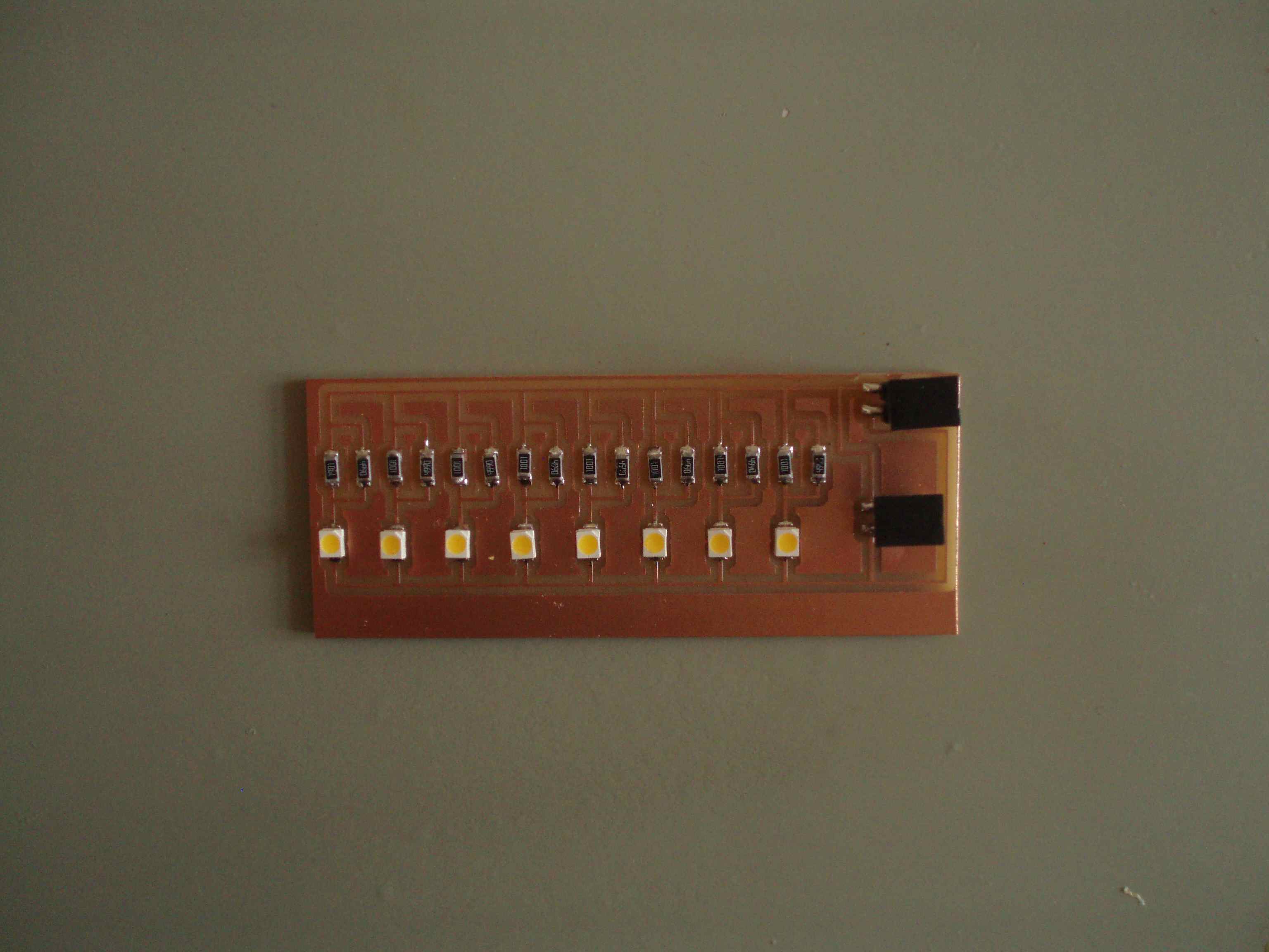
- Two LED boards with eight bright LEDs for strobing
- Hall effect switch board mounted under the board with magnets
- Spindle Speed Control voltage divider board to control spindle speed.
- Spindle on motor salvaged from a SONY turntable
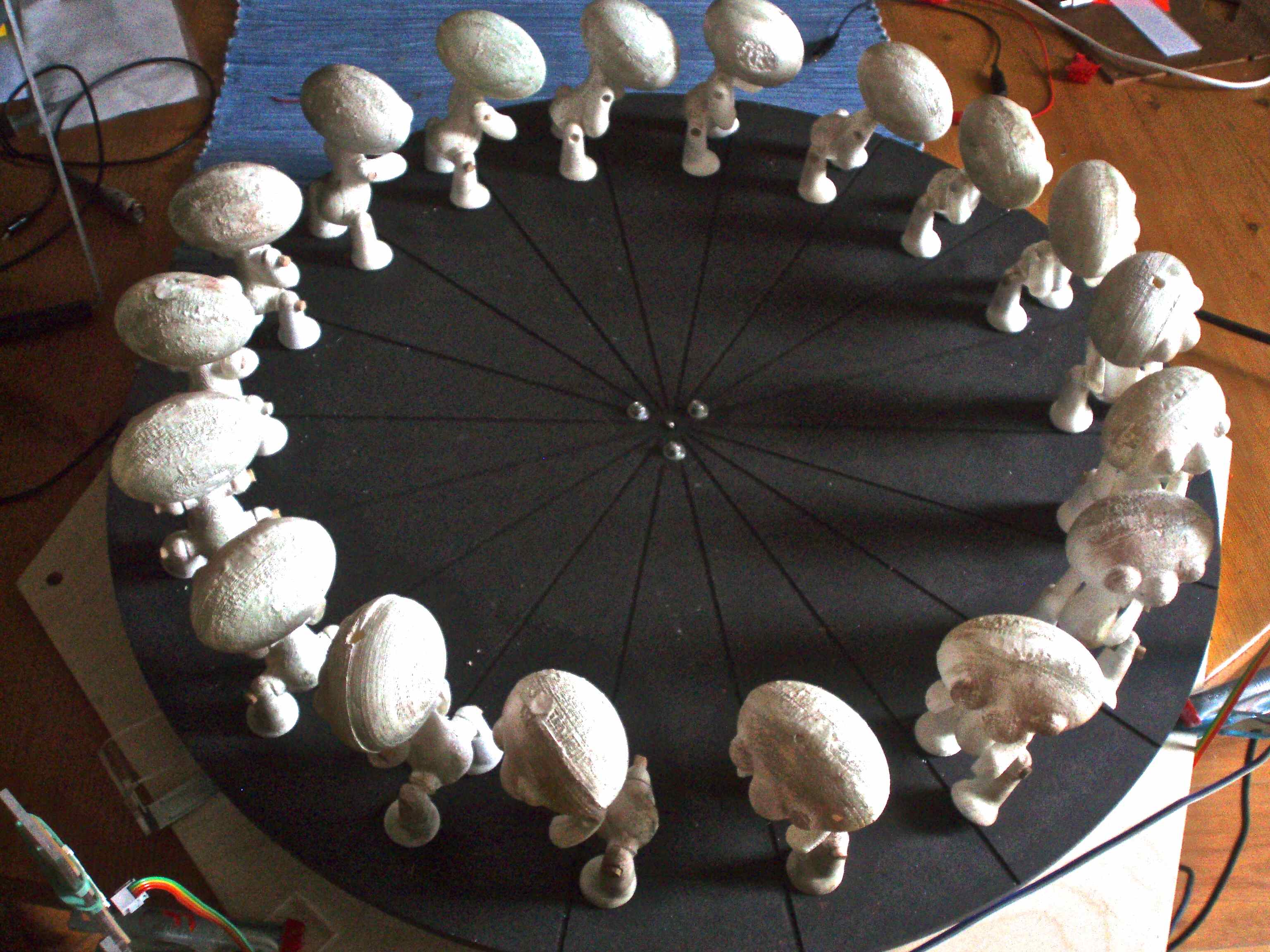
- Platter with eighteen magnets placed equally round perimeter.
- Mounting platform for mounting spindle and motor, platter, and all the circuit boards.
- Eighteen 3D printed and / or cast characters.
Project Schedule
The schedule is documented in assignment Applications and Implications
Hardware

Using the speaker circuit board from the output devices assignments which has a Mosfet and Attiny45. Changed the clock speed on this Attiny45 was from 8 mHz to 16 mHz to get a higher clock rate.
Milling platform and printing necessary parts
Milling a two-sided board
- Side one: For aligning characters, routed lines in board in proportional divisions.
- Side one: Drilled thru (alignment) holes in four corners of the board to align the board when flipping board.
- Side one: Milled out square and remove from ShopBot leaving the left over material attached to sacrificial layer of ShopBot.
- Side two: Flip square over aligning holes and screw to sacrificial layer of ShotBot.
- Side two: Do not change the x or y zero settings.
- Side two: Mill magnet pockets with smaller offset pockets to make it easier to remove the magnets.
- Side two: Mill final circle shape.
- With careful planning the "side two" magnet pockets were centered over lines on "side one".
Click an image to enlarge
LED Boards
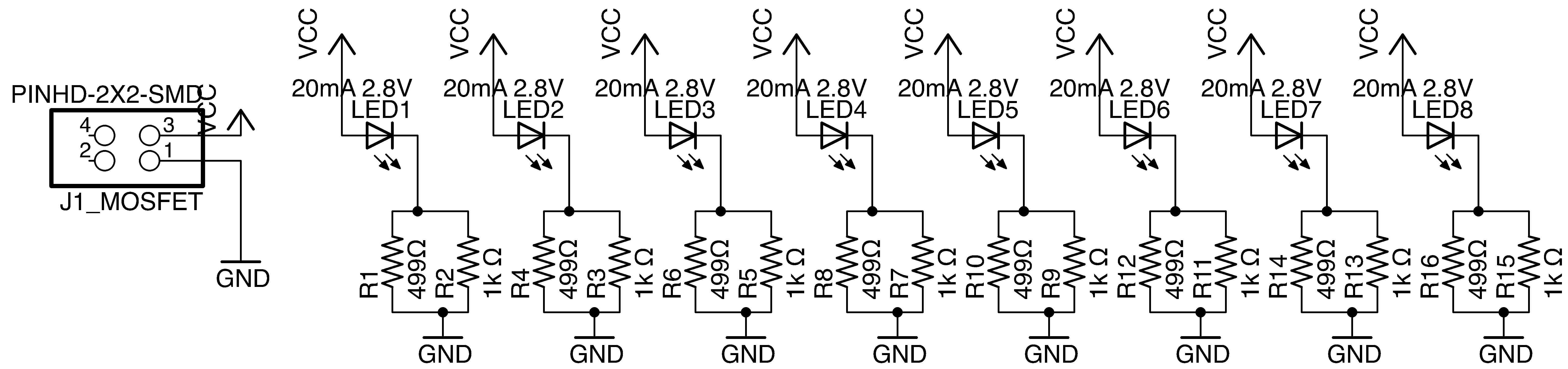
Resistors calculations
The bright white LEDs each need 20 mA constant current, and a forward drop voltage of 2.8V (found in the LED datasheet).
At 9V DC we would need a resistor of: E = iR E = 9V and i = 20 mA
Solving for R:
| R = E/i or (9V - 2.8V)/20mA |
|---|
| 6.2V/(20A x 1/1000) |
| (6.2V x 1000)/20A |
| 6.2 x 50 Ohms |
| 310 Ohms |
 |
| Cut two LED board for strobing |
Check calculations with online calculator
Formula to use resistors in the Fab Lab inventory:
| Rp = 1/(1/R1 + 1/R2 + 1/R3 + … + Rn) |
|---|
| 499 Ohm and an unknown resister in parallel: 310 = 1/(1/499 + 1/Ru) |
| 1/310 = 1/499 + 1/Ru |
| 1/Ru = 1/310 - 1/499 |
| Ru = 1/(1/310 - 1/499) |
| Ru = 818 Ohm, closest greater value on hand is 1 kOhm giving a total resistance of: |
| Rp = (1/499 + 1/1000) |
| Rp = 333 Ohms |
Spindle Speed Control
The spindle is from an old Sony turntable. These old turntables have a magnetic strip painted around the rim under the platter, which is read by a tape head, this is how the turntable achieve speed control. This was no help to me, the Zoetrope speed is controlled using a Voltage divider.
 |
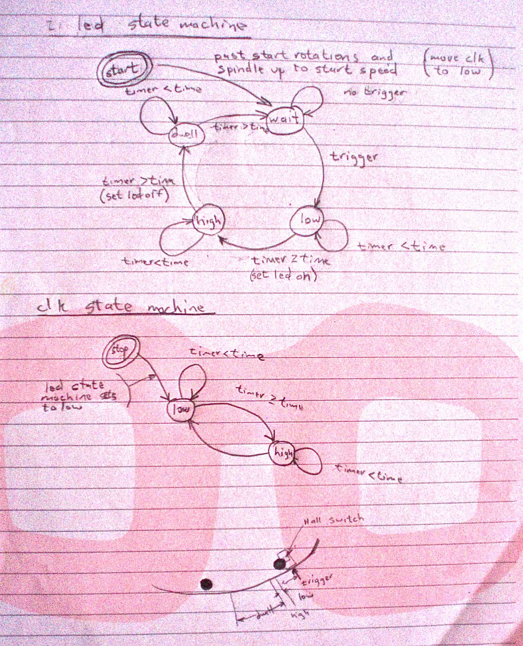
Interrupts and timing
Using one interrupt which happens every twenty-five micro seconds to check the state of the system (Zoetrope's strobing LEDs). The system has five states; START, WAIT, LOW, HIGH, DWELL.
Reference on interrupts
Code
My code for the interrupts, syncing and strobing the LEDs, and controlling the spindle speed can be found here Z_Sync_Strb.c
References
- A number of pdfs explaining AVR Timers non-pdf is on Newbie's Guide to AVR Timers
- AVR forum Atmega8 timer and interrupt
- Attiny45 data sheet
- SONY PS-X555ES turntable service manual
Hall Effect
Comparing Hall Effect Sensor and Hall Effect Switch
Hall effect sensors detect whether a magnet is near. Holding a magnet near the sensor will cause the output pin to toggle. However the Hall Effect Sensor from the Fab Lab inventory did not have the sensitive the Zoetrope needed. After reading the data-sheets and comparing a hall effect sensor and hall effect switch the Zoetrope uses the ultrasensitive Hall-Effect Switch
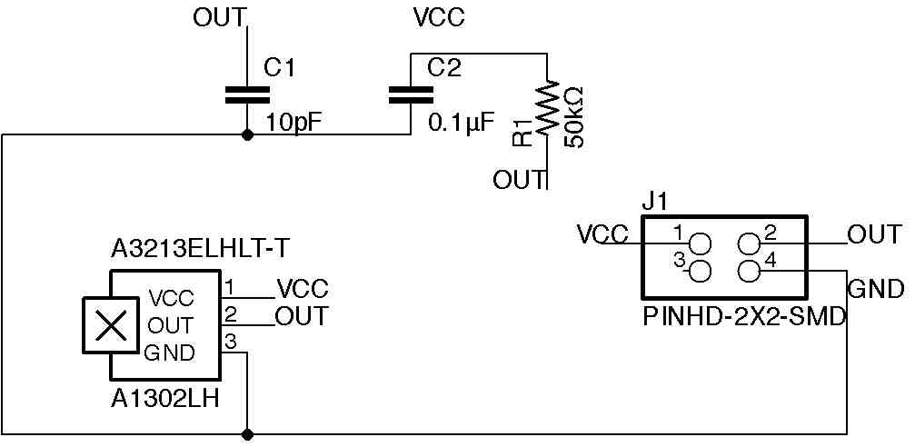 |
| The board with the Hall effect switch is mounted under the platter of magnets to switch on/off the LEDs |
Comparing
Characters
Character design
The character was design in Rhino 3D. The head, arms, and legs are jointed and moveable.
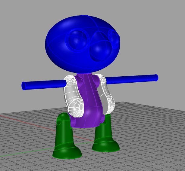 |
| Using Rhino3d created a character with movable joints |
Character creation
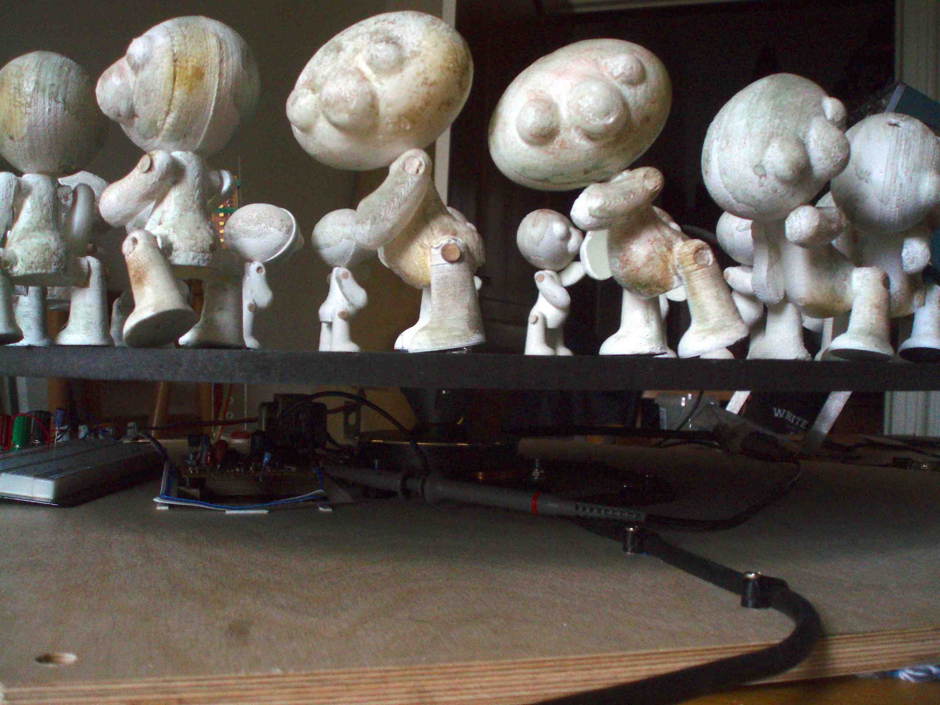
The Zoetrope's 18 duplicate characters are a combination of 3D printing and mold & casting.
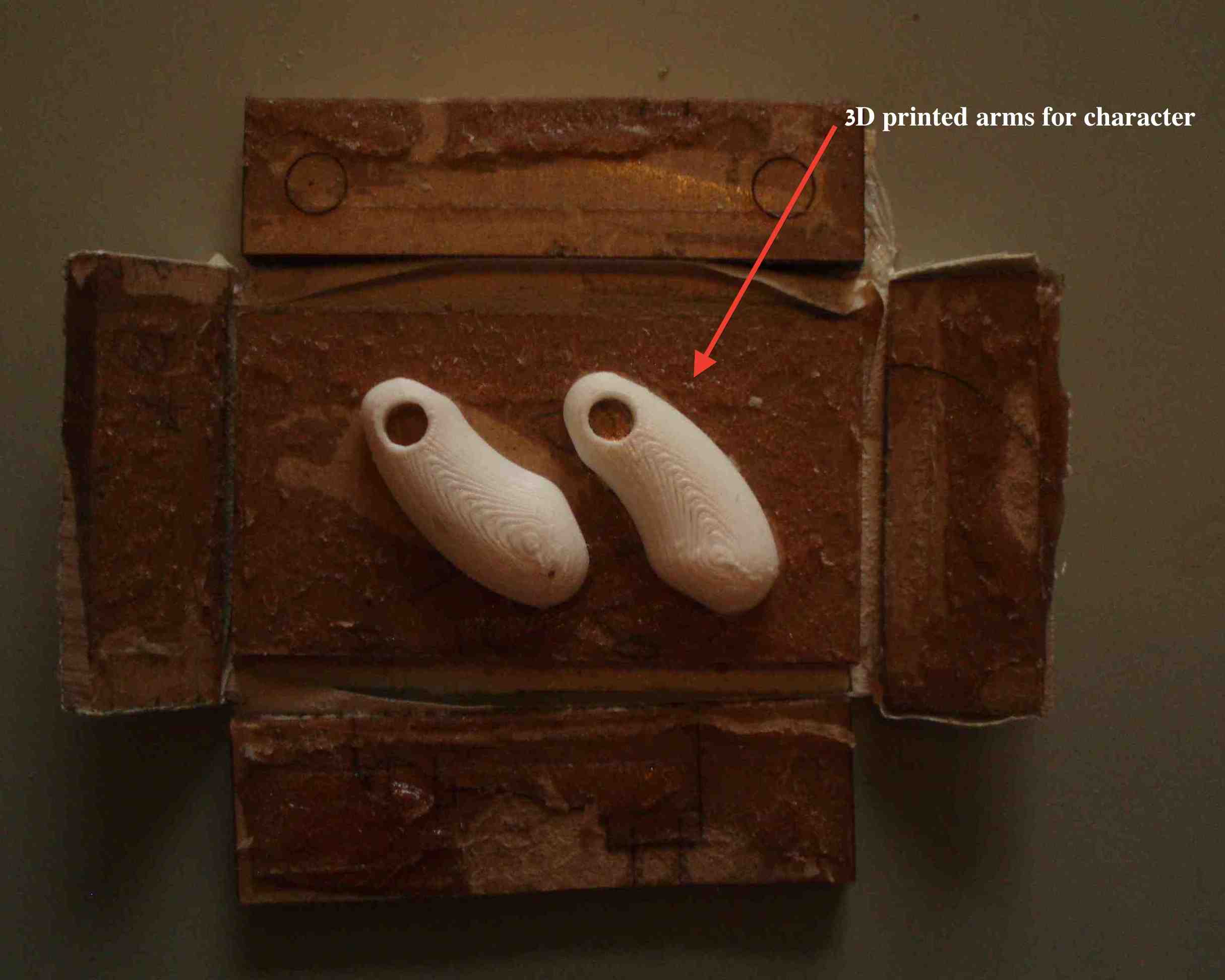
The 3D printer was not able to deliver at the rate necessary to complete the project in a timely manner therefore molds were created for the head, body, and arms.
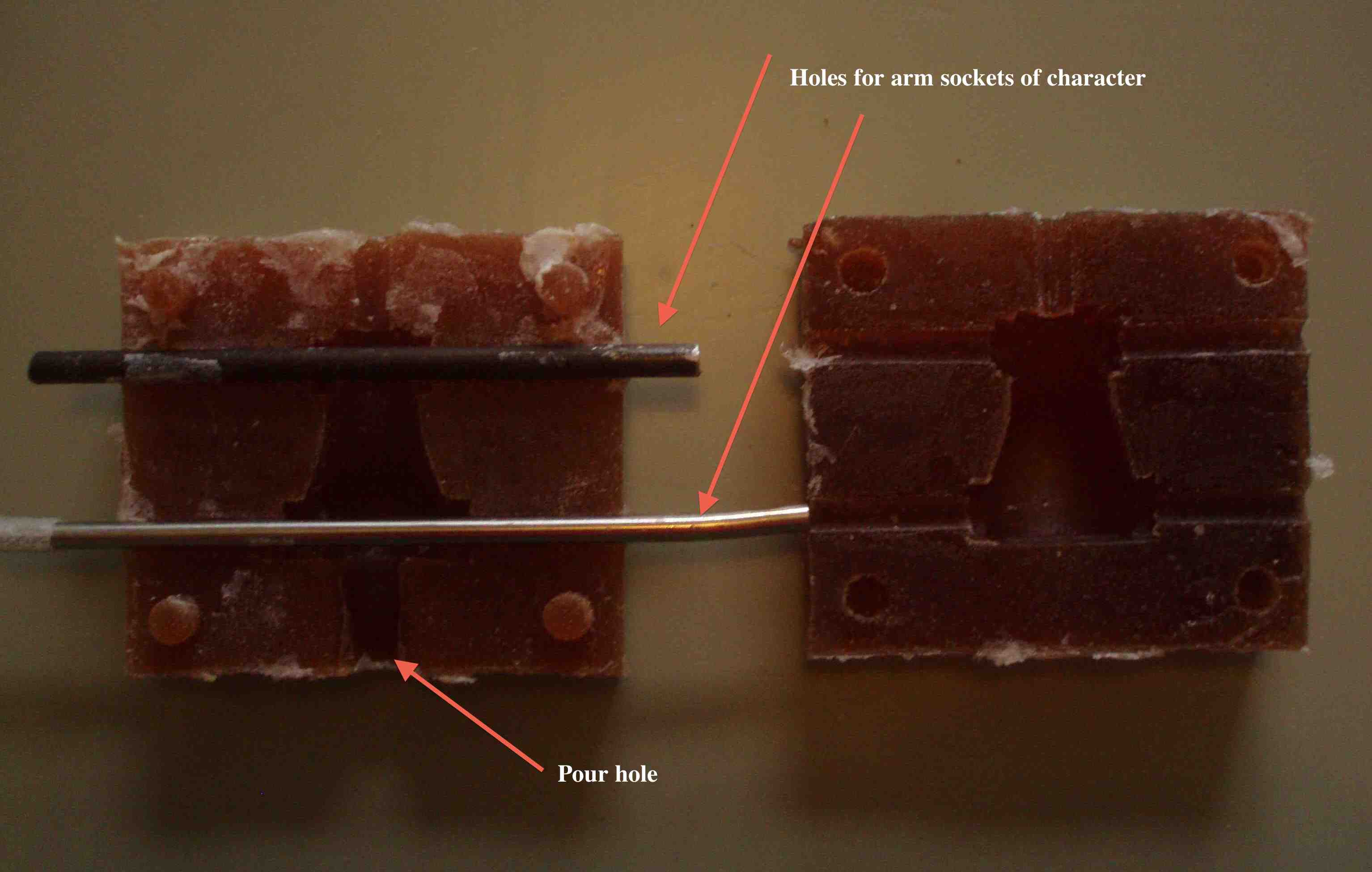
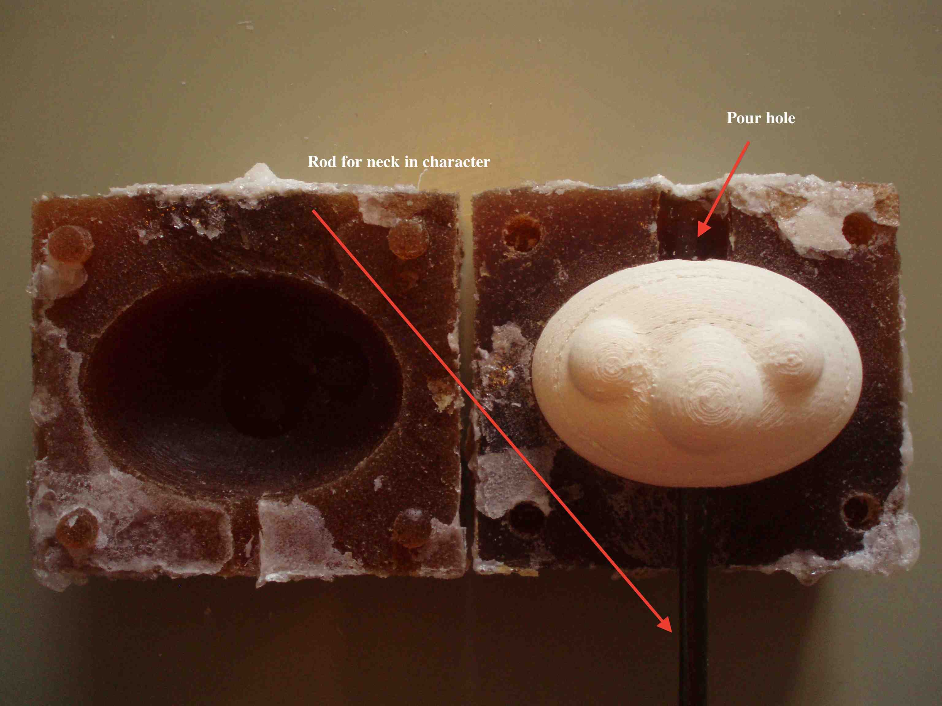
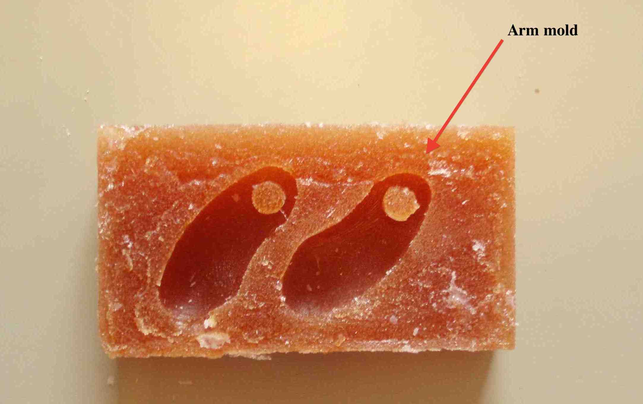
Using the 3D printed body parts each of the needed molds were created. The mold material was Smooth-on's PMC® -121-30 Dry - Urethane Rubber and cast with Smooth-on 325. Before pouring molds I forgot to spray the positives with mold release. This made it very difficult to release the molds however no molds were lost in the process.
 |
|
| Mold made with 3D printed forms (click images to enlarge) | |
 |
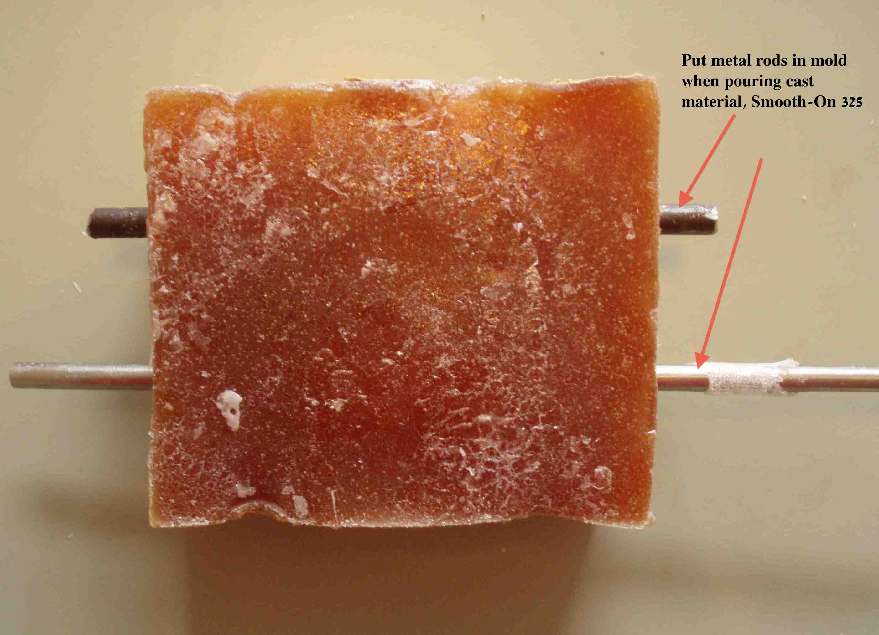 |
| Body mold is poured with 6mm dowels in place, creating holes for arms and legs placement. | |
 |
|
 |
 |
| Head mold are poured with 6mm dowels in place, creating a hole for head placement. | |
 |
 |
 |
|
| Body parts ready for assembling. |
 Lessons learned
- When making multiple items always test with one. I made all the molds for the character all at once. Meaning that I forgot spray all the molds with mold release.
- Re-using the speaker circuit board saved time but designing the board to use an Attiny44 would have give more options.
- After months of second guessing my measurements I finally got a handle on the metric system.