Computer-Controlled Machining
Assignment: Make something BIG
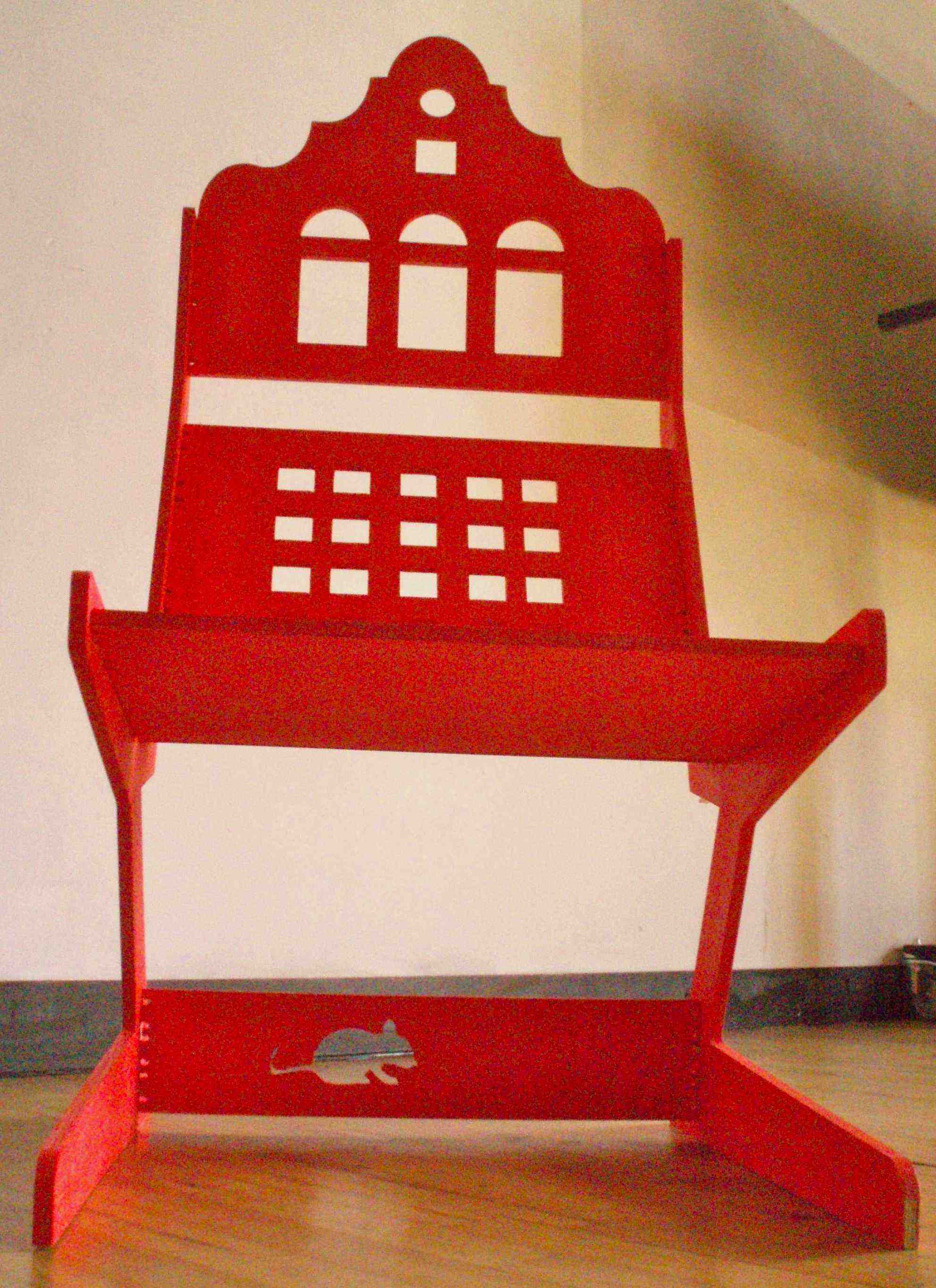
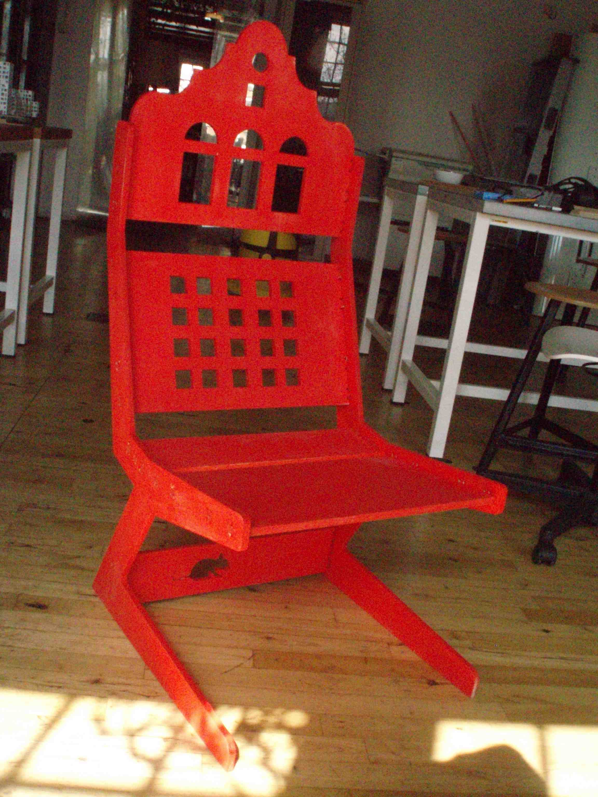 |
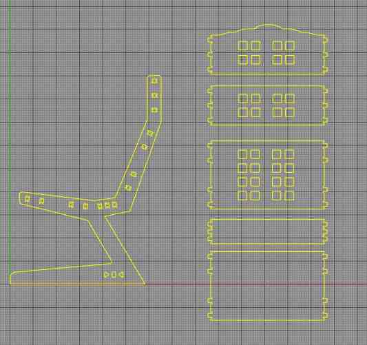
| Chair cut from one sheet of 12mm plywood. |
Designing
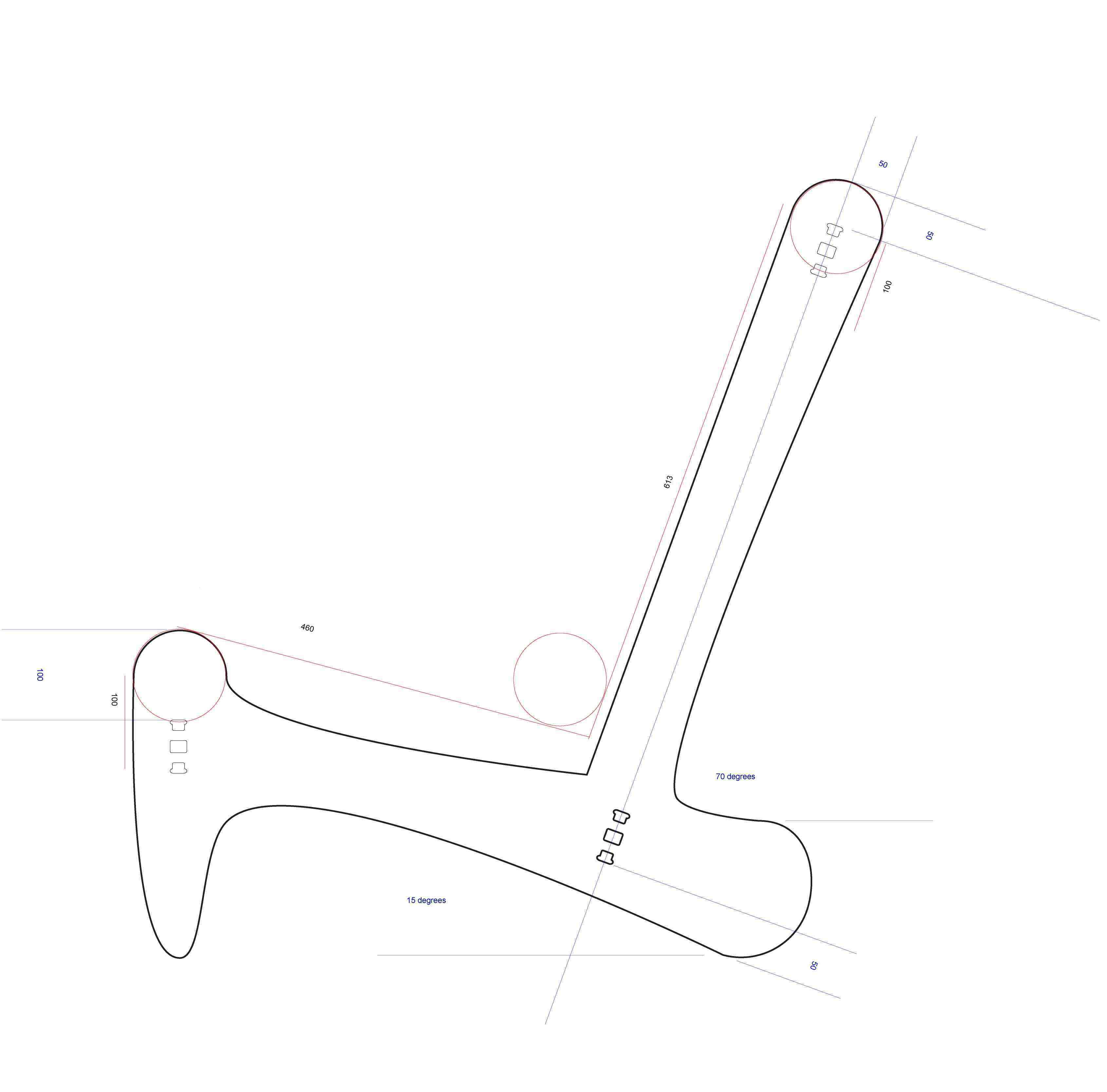
- Designing the chair in Abode Illustrator was a mistake giving it is not most accurate design tool.
- Import initial design from Abode Illustrator to Rhino3d
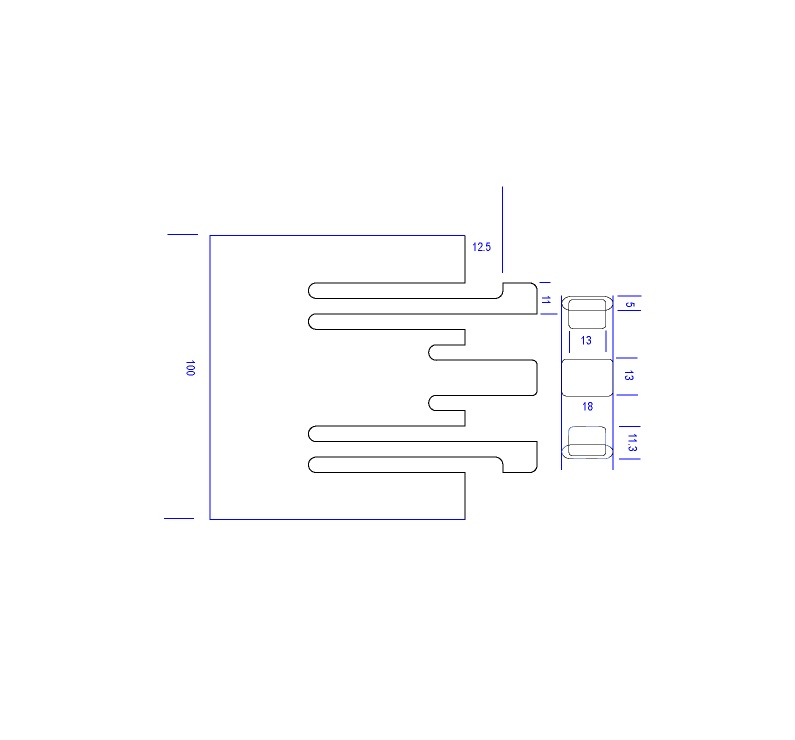
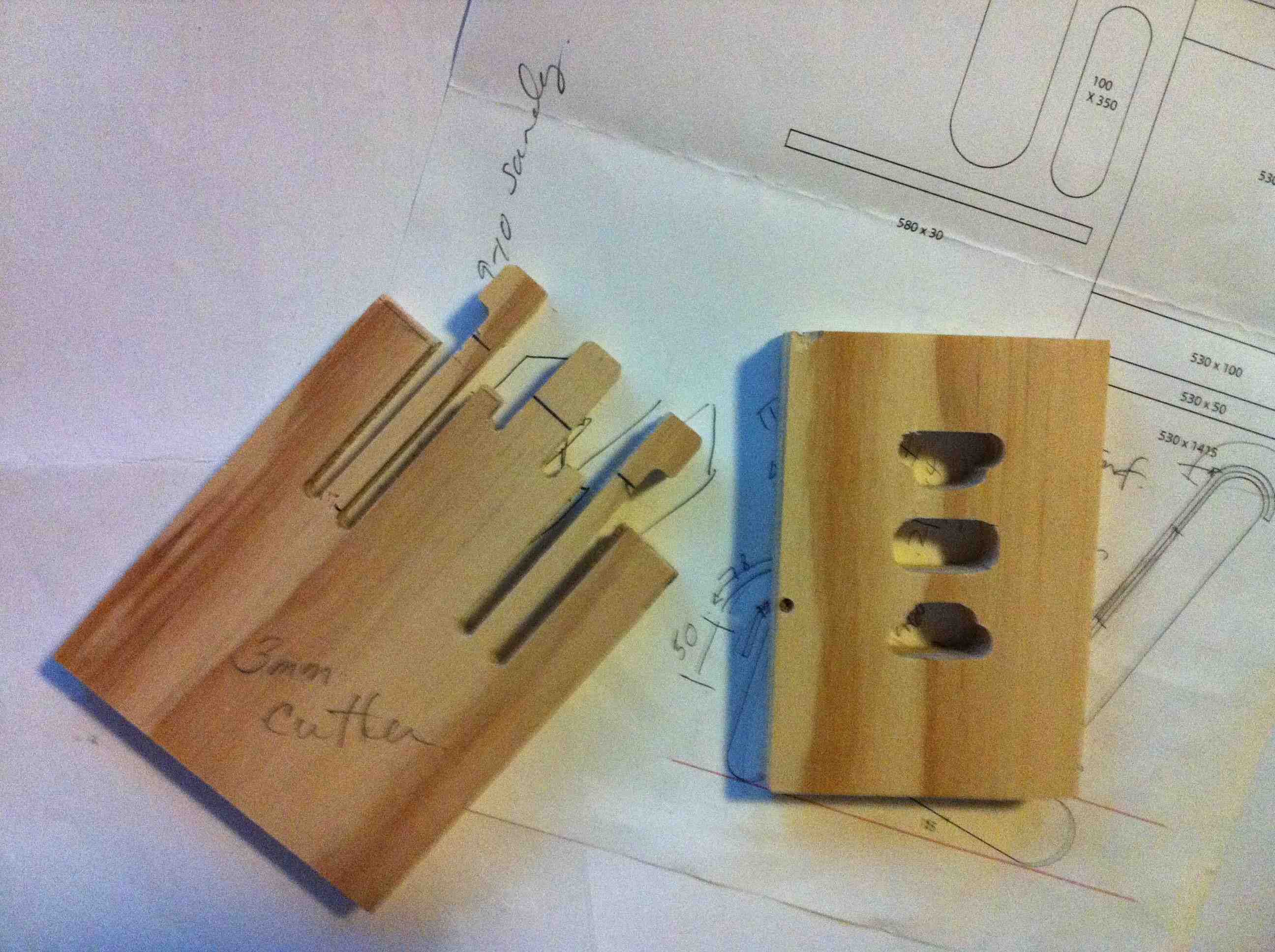
- Wood connection resource: Digital-Wood-Joints
PartWorks
Preparing vector design
- Save drawing as a DXF
- Open PartWorks 2d on ShopBot
- Open the dxf file to cut
- Enter material size width and length
- Enter material thickness
- Set zero (I set my zero to the top of the material)
- Remove the default check "Use origin zero"
- Confirm that the size of your image was exported correctly otherwise you will have to use the option in the path screen to scale
- Select the regions to machine, for example, drill holes to hold down the material.
- Specify the tool details and calculated toolpaths.
- Preview the job.
- Save each toolpath in a seperate file. I usually add a number to the file name so I remember the order, for example, 1DrillPath 2MillPocket 3CutOutline
ShopBot
Cutting design
- Go to abs zero of machine
- Place material on bed of ShopBot
- Jog spindle to appropriate zero position (K - key opens jogging window)
- Record x and y value then zero x and y axis
- Put in selected end mill
- Zero z axis with magnetic bar
- Start vacuum
- Load file
- Start spindle
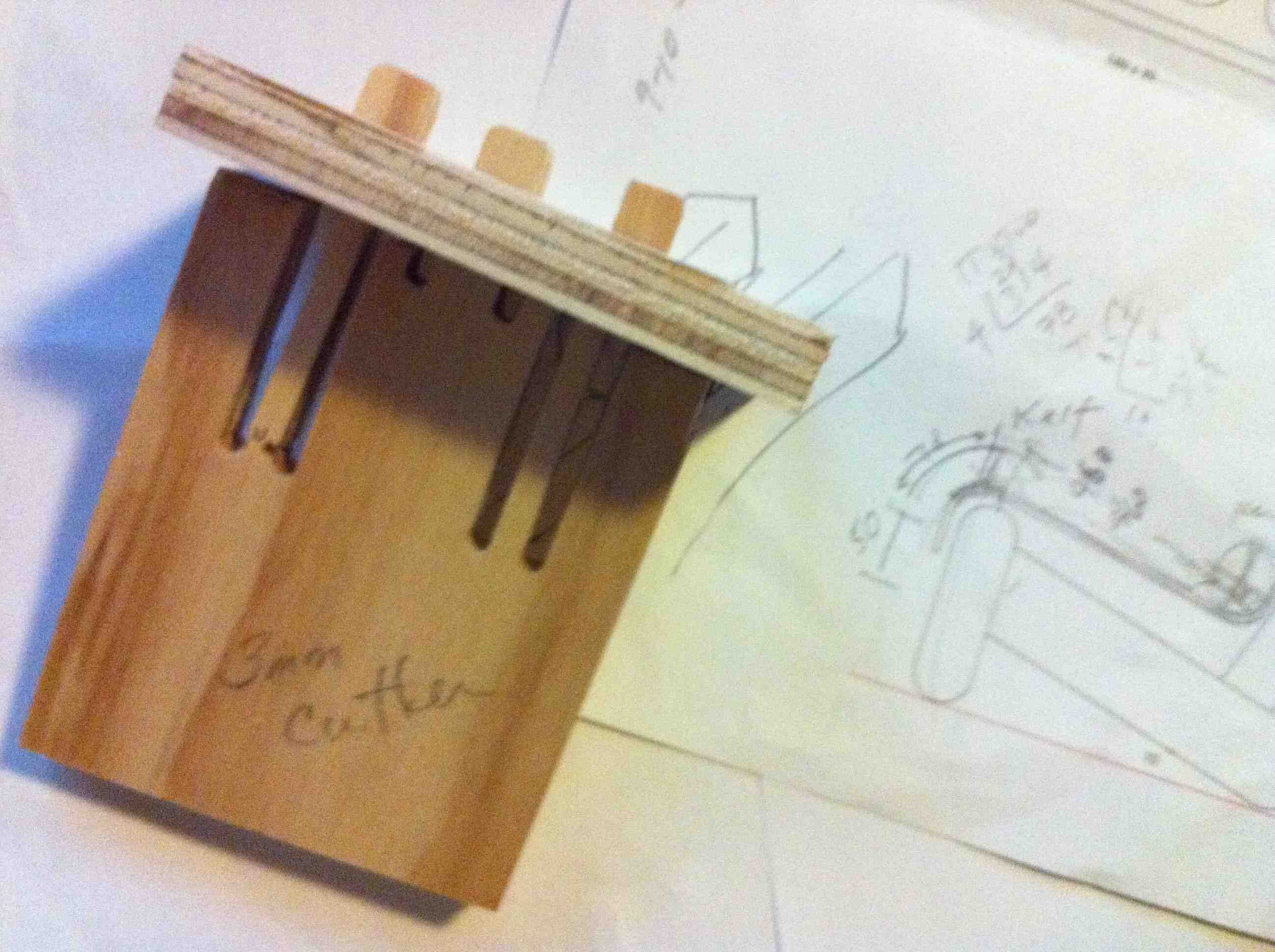
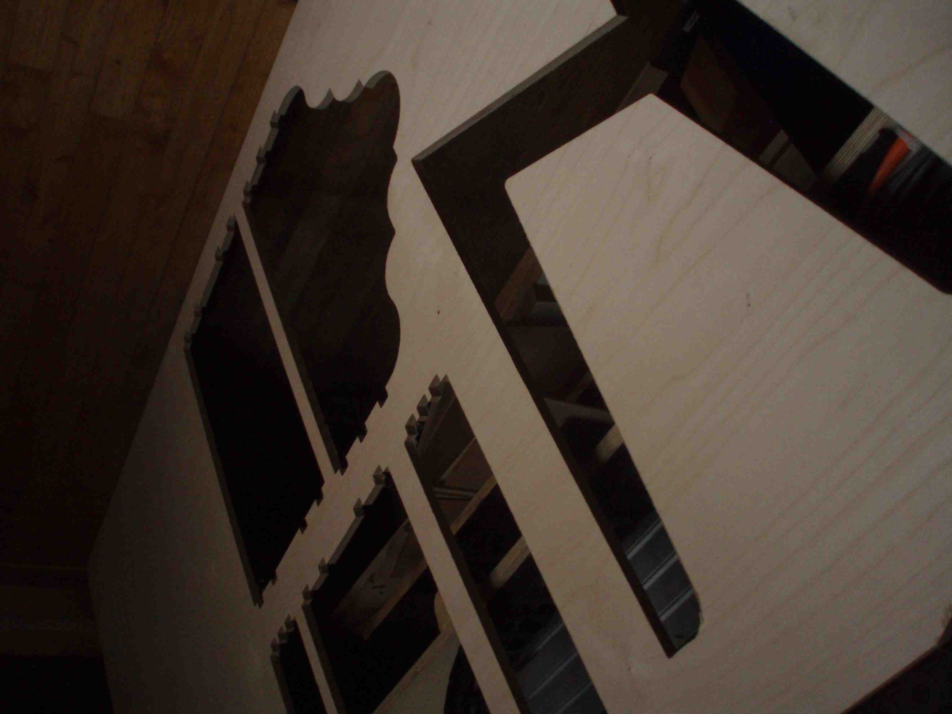
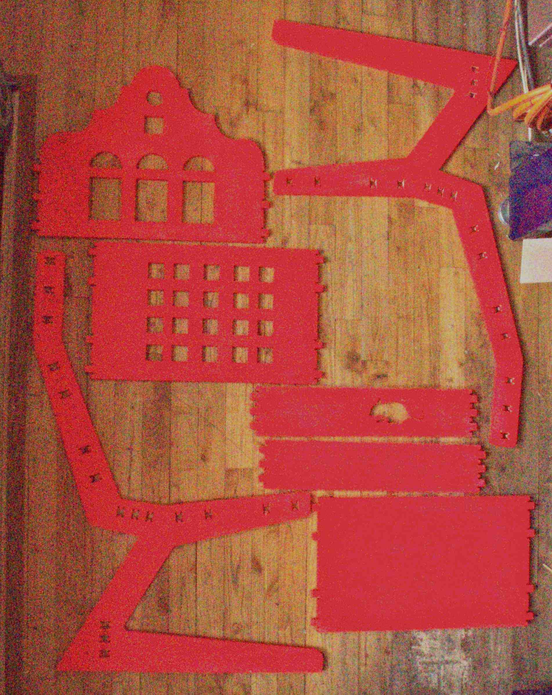
Testing Design
Final Design and Chair
 Lessons learned
- Design with known material size otherwise you will be redrawing design.
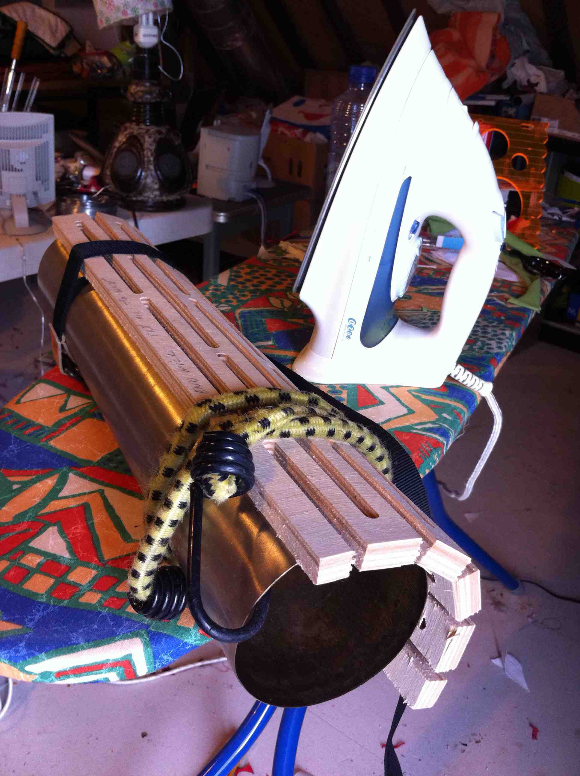
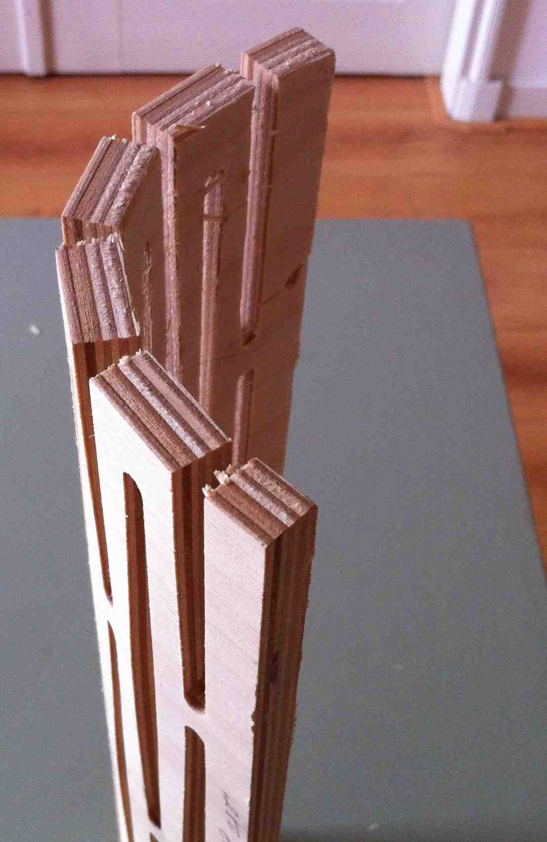
- Test cuts on ShopBot on the endmills and material of your final design.
- Record x and y axis position always before zeroing machine.
- Plan and follow a workflow of each stage of cutting on ShopBot.