Assignments: design and build a wired &/or wireless network connecting at least two nodes
APA asynchronous packet automata
In this week, I tested APA networking with ATtiny44. Normaly data packets are sended with address of its destination but APA sends data with route(like turn left, turn right) to get destination so it can handle more complicated geometry and dosn't need to worry about naming and addressing nodes. It is still experimental thing but I think it is very useful for my project especially when I need to check connections of nodes.
So building my own APA boards and understanding structure of APA was the assaigntment of this week for me.
Board design

To make apa network sample from class page, FTDI board and IO boards are needed. I made two types of shields and new designed main boards like I did in last week. These boards are showed left upper coner in this photo.
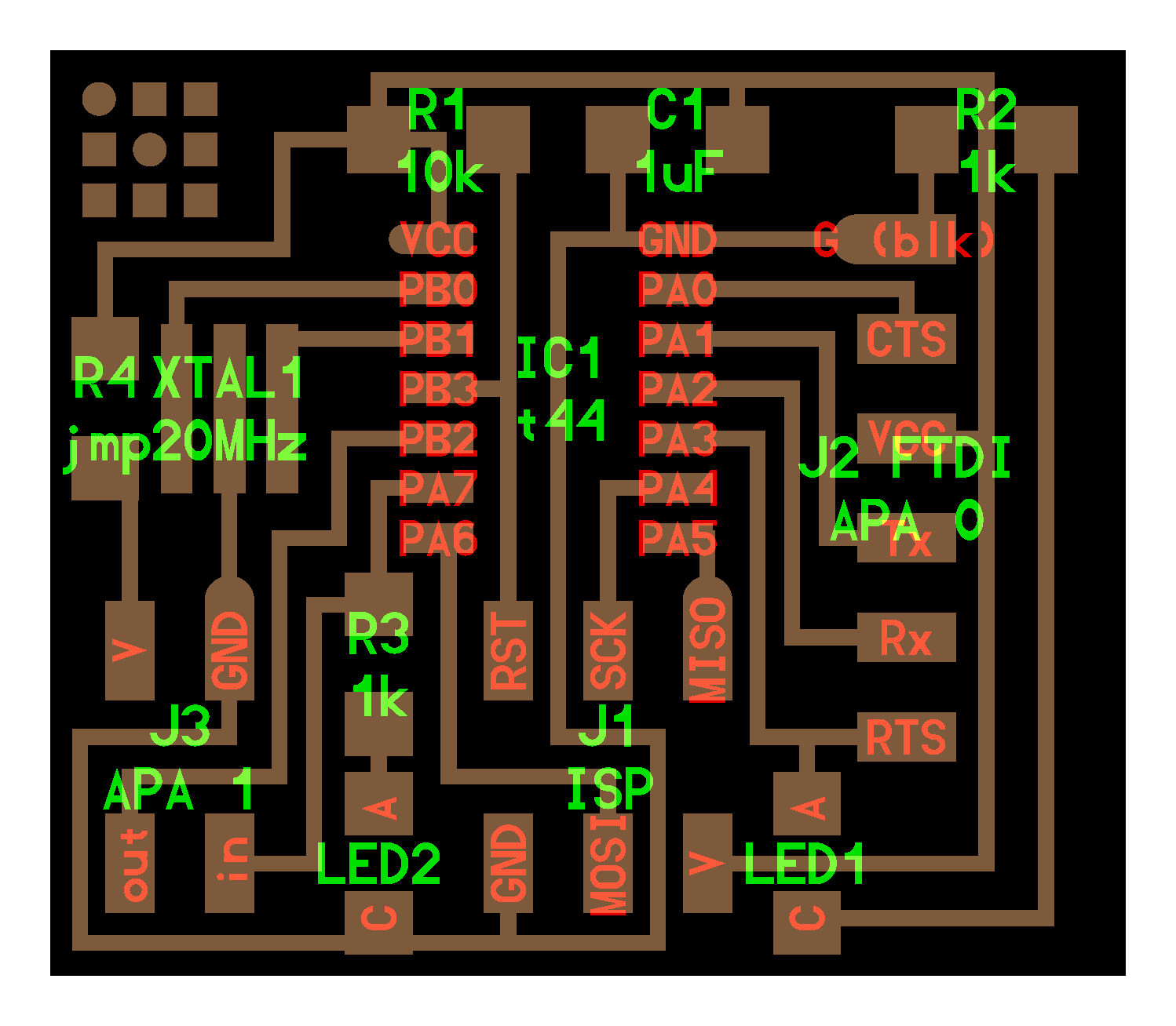
- Main board - I add a slide swith to change power source so it can use not only battery but also power from Shield is available.
- FTDI shield - Based on the layout from FabAcademy page, I designed shield which can be connected with Main board.
- Node shield - Based on the layout from FabAcademy page, I designed shield which can be connected with Main board.
- LED shields for APA - Since node shield has I/O pins, this LED shield is made to connect with it and check output from Node shield.
Main boards are reusable for other purpose by changing shield and vice versa.
Source code for these boards are on FabAcademy page.
For FTDI boards, apa.ftdi.c, Makefile
For IO boards, apa.io.c, Makefile
ON/OFF LED
As first step, I tried turn ON/OFF LED simply. I connected three nodes in a straight line.
Each nodes has three ports which is numbered like image below.
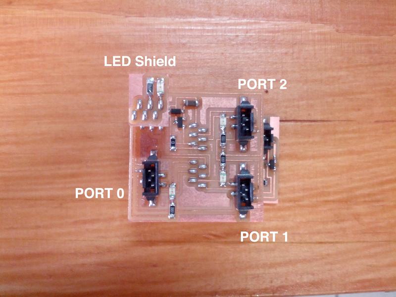
I connected port0 of the first node with port2 of the second node and port0 of the second node with port2 of the third node.
then I typed below command in terminal.
python apa.py /dev/tty.FTDI 115200 "0" "n"apa.py is a python code to send message. when it is excuted, it needs four arguments. the first is name of port FTDI cabele is connected with (/dev/tty.FTDI), the second is bandrate to communicate (115200), the third is route to target nodes data packet should arrive ("0") and the fourth is command to target node("n").
In this case, "0" means the data packet go to port0 of the first node. You can add more long route (like "0154" which means the data packet will go to port0 of the first node and then go to port1 of the second node and so on) to reach more far node.
"n" is one of commands this sample can give to nodes and it means TURN ON LED. If you give "f" instead, it means TURN OFF LED. I'll cover other commands below.
I succeed in controlling LED with APA communication. Here is the video...
Change brightness
As I mentioned above there are some commands to controll nodes. From source code,
- "n" - turn on PWM output
- "f" - turn off PWM output
- "r" - read value of PWM
- "w" - write value to PWM output (like "wxxxx", x could be 0~f since node can receive 16bits as PWM out put)
- "0" - read A/D input pin 0 of I/0 pin
- "2" - read A/D input pin 2 of I/0 pin
I attached LEDs to all I/O pins on nodes to check PWM output.
In the video, Brightness of LEDs are changed be command "w".
Use different routes to reach same node
Next I changed geometry of network like below.

Three nodes make circle so there are two ways to reach one node.
Here is a video showing I turn on/off one LED but I used different route to do that.
Response from nodes
Everytime I send message to Node, Node send back responce to PC like...
$ python apa.py /dev/tty.usbserial-FTFBF4UI 115200 "0" "n"
send packet: {^0|n}
receive packet: {0^|}
{ 123
0 48
^ 94
| 124
 0
 0
} 125
If node doesn't exist at the place route pointed, PC get this massage.
$ python apa.py /dev/tty.usbserial-FTFBF4UI 115200 "0" "n"
send packet: {^0|n}
check_waiting: timeout
By using this character of the system, It could be possible to figure out the geometry of connction of nodes and that I need for my final project.
I'll make visualizer showing connction of nodes in "Interface and Application Programming week".
Resource
APA files: this ZIP file contains Eagle files, PNG for milling, Makefiles, C codes, and list of componets to make boards.