Assignments: measure something: add a sensor to a microcontroller board that you've designed and read it
This week I did...
- Making hello main boards and shields with ATtiny45
- Testing thermistor shield
- Testting step response shield
- Making rotation sensor with step response shield
Milling & Soldering
I don't mention in detail about milling and soldering here since I alreday wrote how to do it BEFORE.
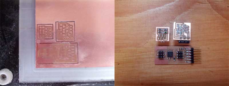
We used new 1/64 end mill for trace this time and result is much cleaner than last time even I don't need to sand surface.
Main board
In the same way as electronics design week, I designed one main hello board and two shields one for sensing tempature and another one for doing step responce.
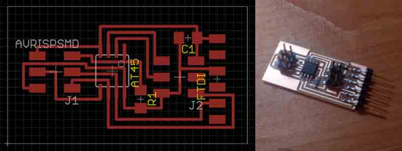
This is main board with ATtiny45. 2x3 pin header located in middle of the board connected with PB3, PB4, PB1, VCC and GND of ATtiny45 for shield. PB1 is used by ISP pins as well but it's available when the board isn't connected with programmer.
Testing thermistor shield
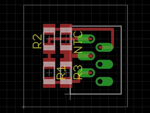
In eagle scheme above, R1~R3 are 10k ohm resistors and NTC is thermistor which change it own resistance depending on tempature.
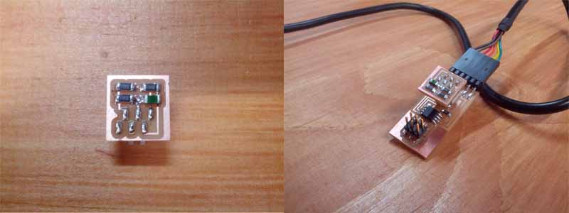
After milling and soldering, I stacked this shiled on main board and tested how it works. Uploading code to chip went well but I got Error meesage below when I tried to run python code.
ImportError: dlopen(/Library/Python/2.7/site-packages/numpy-1.9.0.dev............
  Referenced from: /Library/Python/2.7/site-packages/numpy-1.9.0.dev.............
  Expected in: /usr/lib/libSystem.B.dylib
 in /Library/Python/2.7/site-packages/numpy-1.9.0.dev_ ..... /numpy/fft/fftpack_lite.so
From some forums of Python, it's happen when there aren't modules needed or python is looking for module in wrong place.
So I tried to uninstall the module named "numpy" then re-install like be below.
$pip uninstall numpy
$pip install numpy
Then python code started working without saying any error message.
The video below shows result.
Testing step responce shield
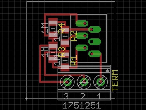
In eagle scheme above, R1~R4 are 1M ohm resistor and I also put terminal pin to the board so I can change conductors connected with ports of ATtiny45 easily. In the design, I use PB3, PB4 as receiver and PB1 as transmitter.
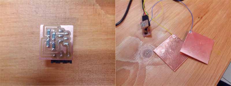
To make conductors for PB3 and PB4, I cutted 6cm x 6cm copper sheets with vinyl cutter and put it on same size acryl then soldered wire to it. In the example code transmitter is PB4 but PB4 is receiver and trasmitter is PB1 in my design so I modify around Line35 in the code.
#define trasmit_pin (1 << PB1)and here is result.
The value shown on screen changes depend on distance between plates and area overlapped each other.
Making Rotation sensor
In the class, Neil mentioned about rotary knob (in this video 44:17~) by using step responce with two semicircular conductors.
But I wondered how it can detect 0˚ ~ 360˚ with two semicircular. For example, let's say one semicircluars overlapped half of area of anohter one and it is supposed 0˚ state then if one of pair rotate 180˚ the area overlapped each other is same. It means the rotation sensor out put same velue at two point.
So I came up with idea to use three 120˚ circle instead of semicircular to detect rotaion like photo below.
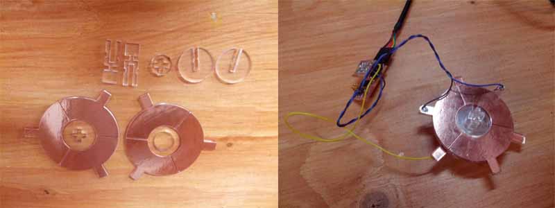
By comparing two value from two receiver, it can sensor 0˚ ~ 360˚ of rotation. Two discs are made of copper sheet and acryl and these are connected with acryl axis. You can check the result in this video.
A probrem is maximum and minimum outputs of two receivers are different even I make it same dimension. And resolution of sensoring is not so high.it' like 90 steps for 360˚.
But still I guess it's very handy to make. You just need copper and acryl the you'll get rotation sensor.
Refference
Resources
Rotation sensor: This ZIP file contais Cutsheet of Acryl and copper tape, Makefiles, C codes and Python codes of interface program.