Final Project Presentation

For the final project we (Mathew Owen and I) have decided to create an inexpensive solar tracking divide to be incorporated wit DIY solar panels. Our goal is to create an open source project that is easy to follow and can be produced by anyone at a low cost.
Jump to:
- The Design Concept -
The concept was to build a low cost solar tracker with a universal mount (for use on any surface, facade or roof) regardless of its shape. In addition we wanted to apply as many skills as possible that we have learned during the course. Rather than just thinking about the most creative or artistic installation, we want to do something practical that will showcase that we have a general understanding of all the units given in the past 5 months.

The design is based on simplicity rather than an artistic installation as one of our goals is for it to be easily replicated (for other diy hobbyist /labs to experiment with). In addition we are using common inexpensive sensors (regular photoresistor), most common servo motors (Futaba S3003 Servo Motor) and regular 6"x6" solar cells (inexpensive and readily available). The rest of the materials will be easily laser cut, 3D printed or milled (possibly molded and cased for larger quantities).
The video above was our first setup which we based our design off of. A working prototype of our solar tracking panel that will help us learn from before investing in more expensive materials (such as solar cells and acrylic).
- The Electronics -
The electronics were the most important part to get ready before the rest as we could test our designs as we go. So we made it our priority to get an early start to getting them finalized.
Prototyping with breadboards
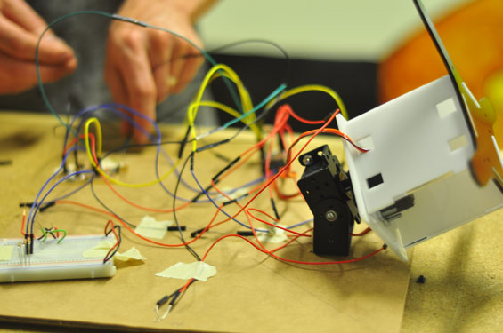
The first electronics prototype we created were using the Fabduino we made in week 8 (in Embedded Programming) and a regular breadboard connecting the fabduino, the photoresistors and the servo motors.
Replacing Breadboard with Milled PCB Board

The electronics have been made exactly to replicate the breadboard once the code ran without any errors. I didn't have enough resistors to solder to the board so we mounted through hole resistors to the prototype servo/photoresistor board. This is then connected to the Fabduino.
The Final Custom PCB

The final traces for milling on the Roland MDX-20. The file is simply a Fabduino mixed in with a custom board for the photoresistors and servo motors. Click to download the full size image and here for the exterior file.

Milling the board out on the Modela. It took about 5 attempts before I had the first working board. Many traces were too close to each other and would not mill properly. After redesigning it several times I finally had a board that looked decent enough for testing.

The SPF-3 (Servo, Photoresistor & Fabduino Board - 3rd test of the design, finally working!) The design of the final board is simply incorporating the Fabduino with the custom made board into one final board.

The Fabduino part was attached first so I could burn on the bootloader.

Part one finished of the boards (ready to burn bootloader).

The Fabduino part was attached first so I could burn on the bootloader.

The final assembly after Fabduino had successfully burned the bootloader without any errors (since I was limited with components and time I decided to first complete one section before moving on to the next).
PCB Enclosure

The final enclosure design (download Rhino file or the dxf file), labeled and thoroughly tested. Shown above on the laser bed, cut out and ready for assembly.

The final assembled enclosure showing the holes for connection with the servo motors and photoresistors.
- The Pan / Tilt Bracket & Mount -
The design file for the pan and tilt bracket as well as the mount on/in which the bracket will be placed.

The mount being printed using the Replicator 2.

The interior has been designed for a standard servo to fit inside (very snug, in fact for the Futaba s3003 it fits tight without the need of extra screws or glue).

The press-fit connection between the servo and the mount make it ideal as the holes on the top are minimal. No need for extra hardware either.

The complete two-part servo mount, attached to the base plates.

The pan / tilt bracket is lasercut from 3mm or 1/8" acrylic, after which it is placed on a heat strip and bent into shape. We engraved lines to help us get a flawless result.

The bent acrylic. Works perfectly and is done in just a few minutes. Our plan was to 3D print the bracket parts, but since this was such a fast process we decided it would be great to use. For future projects we will develop a better bracket for outdoors.

The bracket shown on top on the mount. Also shown is the foot of the mount, another component that fits very tight together without the use of any extra hardware or adhesive.

All 4 pan-tilt mounts shown above with an early panel prototype attached to the mounts.
- The Panel -
The panel will be done as several tests, using solar cells as its main component along witht he sensors (photoresistors).
Panel Design 1 - Composites

The solar cells. At about $1.50 each they are quite affordable for a diy project. They are rated at 5Watts each giving 0.5v of power. Our total system can generate up to 70W at 18V (enough to power both our laptops during our upcomming roadtrip).

Soldering the tabbing and bus wire to the solar cells. A long and tedious process on the first 10 cells. After about 6 hours and 10 broken and burned cells later I started to get the hang of it (also buying a decent soldering iron helps - I got a flat eaded 40W Weller, 60-80W seems to be preferred by many).

Wiring the back of the panel which will be covered in cloth and resin to form a composite solar panel. The nice thing about this is that all the electronics on the back of the panel are neatly tucked away.

Placing the panel into the mold made from Oomoo (which was poured into a frame created on the shopbot).
![]()
Using silicone to enclose the solar cells as we do not want resin seeping under them. Most types of resin turn yellow in a short amount of time (one week to one month in direct sunlight) which will greatly affect the power. This short amount of time makes it very unsuitable for the enclosure of solar cells.

Applying cloth the the back of the panel. We cut the cloth to size using the laser cutter which cut very nicely at high speeds. The cloth will be painted with resin when applied.

Applying resin to the cloth.

Conclusion is that is is far too heavy for the servos that we have. It also does not look very good at all. Another test will be done with less heavy materials and as an easier method as we are simply not happy with the results of this.
Panel Design 2 - Sandwich Panel

The back plate for the panel (similar to the front, just has an extra hole). This is very thin acrylic, about 0.7mm thick. The plate will be glued to the bacl of the solar cells using silicone and will be attached to the front using m3 bolts.

Soldered solar cells with a plus and minus wire shown.
![]()
Applying a small amount of silicone to the back of the panel for attachment of an acrylic back plate.

Pressing down the acrylic to attach the solar cells to it using silicone.

The panel flipped right side up showing the solar cells.

The front of the final panel. Lightweight, partially transparent panel which turned out to be the easiest to fabricate, cheapest and most pleasant to look at.

The reverse side, simple and minimal use of materials, just plexiglass and silicone is shown (along with a few bolts).
- The (nearly) Finished Product -

Before assembling we wired the sensors along the back side of the panel. For now we have cut the solar cell cables short. As soon as the project is in the next phase we can reconnect them and have them power the unit directly.

The main components ready for final assembly. The panle in the background, the pan / tilt bracket and mount in the middle and the electronics in its enclosure in the foreground (and all sitting on top of the main "roof" base panel).

The Electronics fully wired up, only have to connect the sensors (ordered by Left, Top,Middle, Bottom and Right). An easy connection and labeled enclosure makes it easy to connect.

The back of the final panel, attached and working!

The image shown above is one of the four final panels. As we ran short of time we only managed to fully complete one panel.
The final design working. Click on the video above for a quick demonstration of how it works. When installed there will only be one lightsource (the sun) and not multiple lights, which is the reason we had to turn off the light for best effect.


