


Output devices
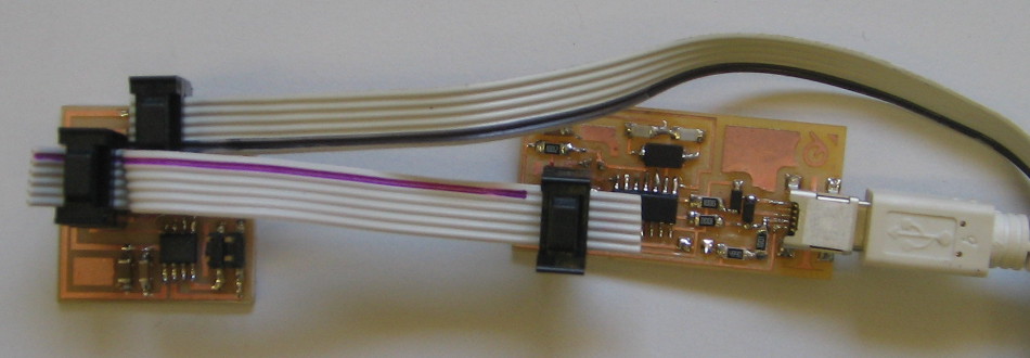
This week I made the DC-motor controller, using the A4953 motor driver. Since this circuit is not using the FTDI-cable, it has to be connected to another power-supply for programming.
I used an old PC power-supply for connecting it to 12V DC. For switching it on you can usually connect the green wire to ground (look in the datasheet for the cables where the power switch is connected)
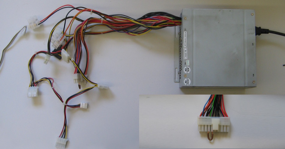
On most power supplies there is a label explaining the different supply voltages. In my case I used a yellow wire for +12V and one of the black ones for ground.
In the image you see me using a red +5V cable connected with a screw joint. This didn’t work. I think the voltage has to be a bit higher than 5V for the regulator to work. The Attiny was working with the 5V supply, sending values to the motor driver, but none of the motors turned.
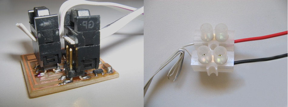
I took a 12V connector from an old motherboard for having a nice connection to the motor that plugs to the power-supply. For connecting to the board I used the 6-pole connectors from the ISP-cables, only connecting the necessary wires.
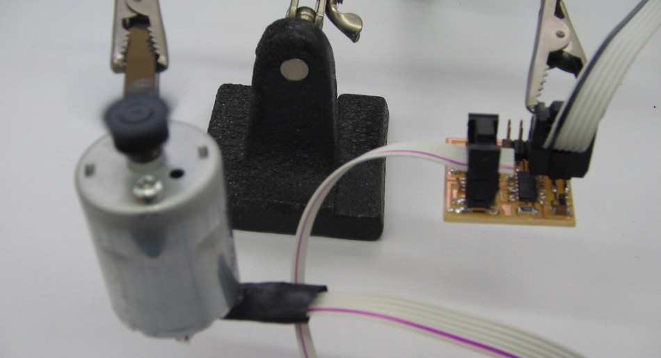
The motor is one that I took out of an old printer.
By changing the values for
fast_off_delay()
medium_off_delay()
slow_off_delay()
in Neils hello.H-bridge.44.c (lines 25 -27) I adjusted the speeds for the three different velocities.