What We Were Asked to Do
Group Assignment
- Send a message between two projects
- Document the process and findings
Individual Assignment
- Design, build, and connect wired or wireless node(s) with network or bus addresses and a local input and/or output device(s).
What I Built
I connected two boards over a wired serial link — an Arduino Nano as the sender with a push button, and an Arduino UNO R4 WiFi as the receiver with its built-in LED matrix. Pressing the button sends a "PRESS" message over UART, which triggers a beating-heart animation on the matrix running at 72 BPM for 5 beats.
Communication Flow
What is UART?
The protocol I used to connect the two boards is called UART — Universal Asynchronous Receiver-Transmitter. Breaking it down word by word:
U — Universal
It works across different devices, manufacturers, and microcontrollers. Any board with a serial port can talk to any other — it's not tied to a specific brand or platform.
A — Asynchronous
There's no shared clock wire between the two devices. Instead, both sides agree on a speed upfront — called the baud rate (in this project, 9600 bits per second) — and each device uses its own internal clock to time the bits. As long as both are set to the same rate, they stay in sync without needing an extra wire for timing.
R — Receiver
One side of the connection is always listening — the RX pin. In this project that's the Arduino UNO R4, sitting on Serial1 (pin 0), waiting for incoming data from the Nano.
T — Transmitter
The other side sends — the TX pin. That's the Arduino Nano, which transmits "PRESS\n" over its TX pin whenever the button is pressed.
In practice, UART only needs two wires for full two-way communication (TX and RX) plus a shared ground. For this project I only needed one data wire — Nano TX → UNO R4 RX — since the communication is one-directional.
Wiring & Pin Mapping
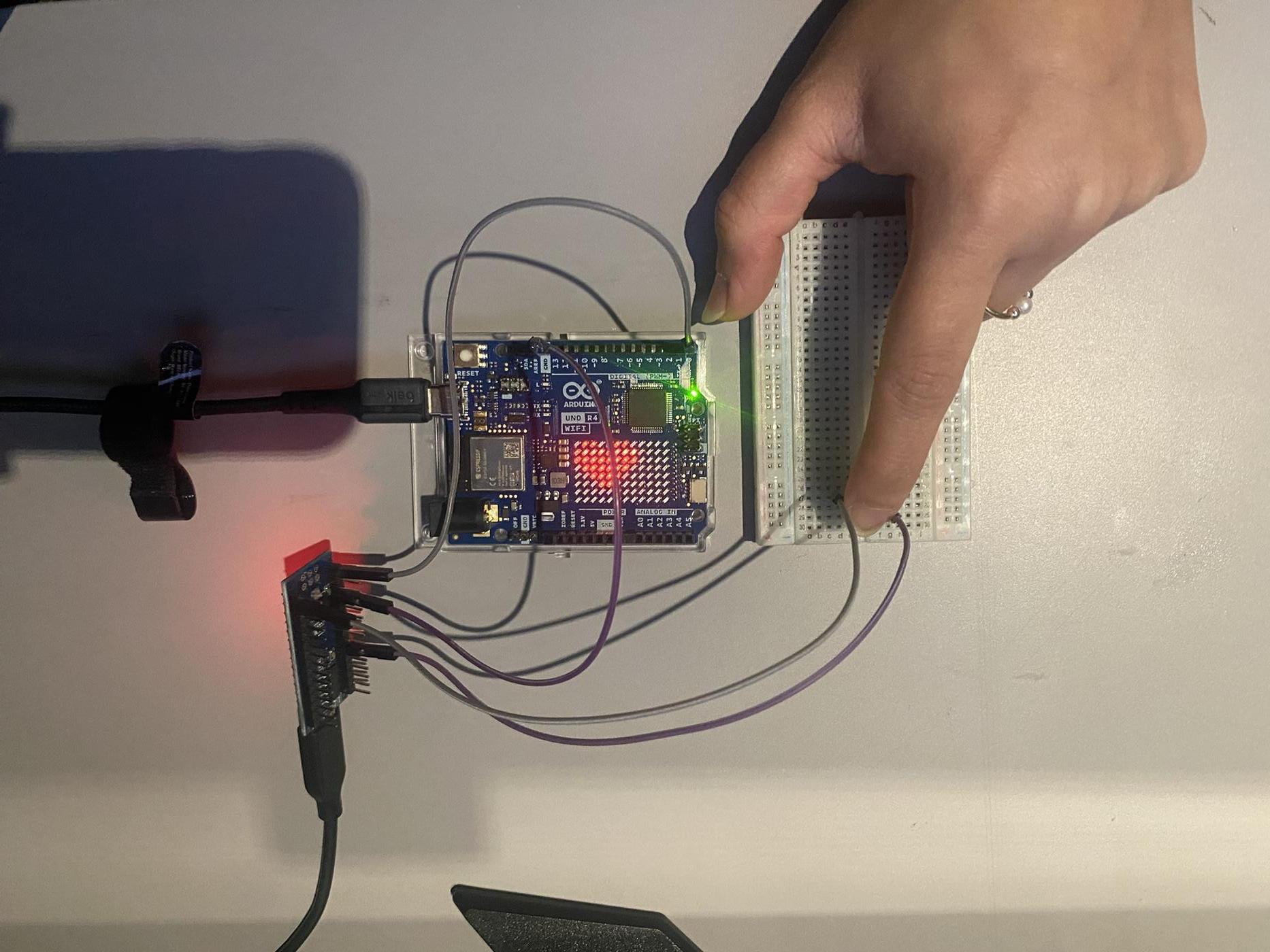
The connection between the two boards is a direct UART wire: Nano TX → UNO R4 pin 0 (Serial1 RX). Both boards share a common GND. The button is wired between Nano pin 7 and GND, with INPUT_PULLUP enabled in firmware so no external resistor is needed.
| Connection | Nano (Sender) | UNO R4 (Receiver) |
|---|---|---|
| Serial data | TX (pin 1) | RX — Serial1 (pin 0) |
| Ground | GND | GND |
| Push button | Pin 7 → GND | — |
| LED Matrix | — | Built-in (no wiring needed) |
| Baud rate | 9600 | |
Wiring Diagram
The diagram below shows the physical connections between the two boards. Only two wires are needed: one data wire (Nano TX → UNO R4 RX) and a shared GND. The button is wired directly between Nano pin 7 and GND with no external resistor — the internal pull-up handles the reference.
⚠ AI-generated diagram [Prompt: "Create an inline SVG wiring diagram showing an Arduino Nano connected to an Arduino UNO R4 WiFi over UART — Nano TX pin 1 to UNO R4 Serial1 RX pin 0, shared GND, and a push button on Nano pin 7. Label all pins and wires with a legend."]
How the Devices Send and Receive Data
The Arduino Nano is the transmitter and the UNO R4 WiFi is the receiver, communicating over a one-way UART link at 9600 baud. Both boards call Serial.begin(9600) / Serial1.begin(9600) in setup() — that's all the "connection" UART needs. No handshake, no pairing.
Why Serial1, not Serial?
Serial on the UNO R4 is the USB port (Serial Monitor). Serial1 is the hardware UART on the physical pins — pin 0 is where the Nano's TX wire connects, so the firmware must read from Serial1.
When the button is pressed, the Nano sends the ASCII string "PRESS\n" over its TX pin. The UNO R4 reads incoming bytes with Serial1.readStringUntil('\n') — the newline tells it where the message ends. After a .trim() to remove whitespace, it checks if the string equals "PRESS" and, if so, starts the LED animation.
Sequence — One Button Press
Button pressed
Nano pin 7 goes LOW. Edge detection (lastState) ensures the message fires once per press, not while held.
Nano sends "PRESS"
Serial.println("PRESS") transmits 6 bytes over TX at 9600 baud. A 200 ms delay debounces the button.
UNO R4 reads the message
Serial1.available() detects incoming bytes. readStringUntil('\n') assembles them into the string "PRESS".
Match → trigger animation
If the trimmed string equals "PRESS", the beating flag is set and the heart animation plays for 5 beats at 72 BPM, then the matrix clears.
Code
Arduino Nano — Sender
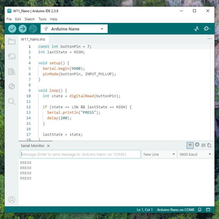
Reads the button on pin 7. When pressed (LOW), prints "PRESS" over Serial and waits 200ms to debounce.
const int buttonPin = 7;
int lastState = HIGH;

void setup() {
  Serial.begin(9600);
  pinMode(buttonPin, INPUT_PULLUP);
}

void loop() {
  int state = digitalRead(buttonPin);

  if (state == LOW && lastState == HIGH) {
    Serial.println("PRESS");
    delay(200);
  }

  lastState = state;
}
Arduino UNO R4 WiFi — Receiver
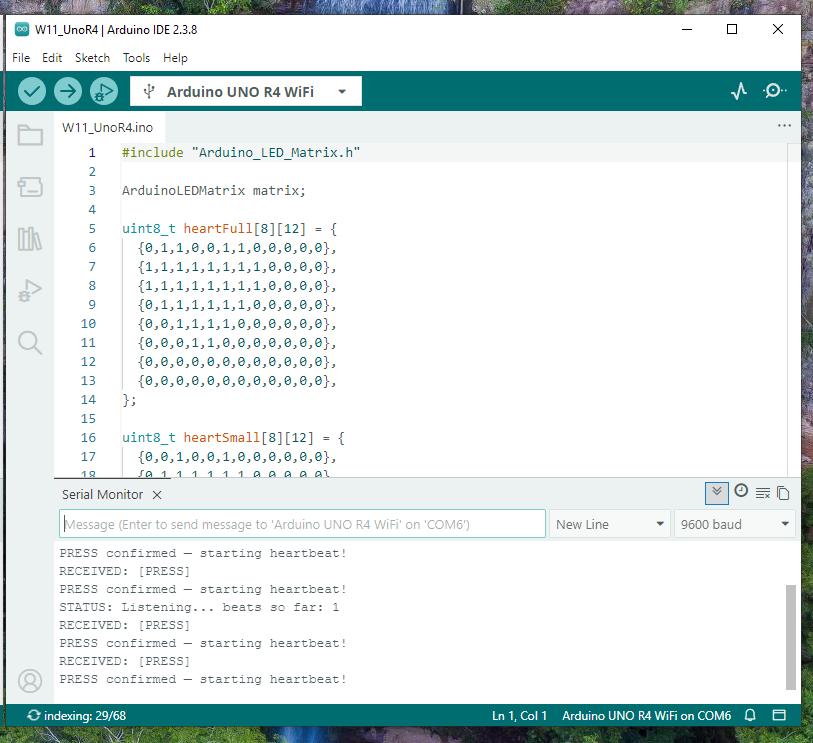
Listens on Serial1 (pin 0). When "PRESS" arrives, it runs a 5-beat heart animation at 72 BPM — alternating between a full heart frame and a smaller one to create the pulse effect.
#include "Arduino_LED_Matrix.h"

ArduinoLEDMatrix matrix;

// 12×8 heart frames
uint8_t heartFull[8][12] = {
  {0,1,1,0,0,1,1,0,0,0,0,0},
  {1,1,1,1,1,1,1,1,0,0,0,0},
  {1,1,1,1,1,1,1,1,0,0,0,0},
  {0,1,1,1,1,1,1,0,0,0,0,0},
  {0,0,1,1,1,1,0,0,0,0,0,0},
  {0,0,0,1,1,0,0,0,0,0,0,0},
  {0,0,0,0,0,0,0,0,0,0,0,0},
  {0,0,0,0,0,0,0,0,0,0,0,0},
};

uint8_t heartSmall[8][12] = {
  {0,0,1,0,0,1,0,0,0,0,0,0},
  {0,1,1,1,1,1,1,0,0,0,0,0},
  {0,1,1,1,1,1,1,0,0,0,0,0},
  {0,0,1,1,1,1,0,0,0,0,0,0},
  {0,0,0,1,1,0,0,0,0,0,0,0},
  {0,0,0,0,0,0,0,0,0,0,0,0},
  {0,0,0,0,0,0,0,0,0,0,0,0},
  {0,0,0,0,0,0,0,0,0,0,0,0},
};

const int BPM = 72;
bool beating = false;
int beatCount = 0;
const int totalBeats = 5;

void beatHeart() {
  int beatInterval = 60000 / BPM;  // ~833ms per beat
  matrix.renderBitmap(heartFull, 8, 12);  delay(80);
  matrix.renderBitmap(blank, 8, 12);      delay(60);
  matrix.renderBitmap(heartSmall, 8, 12); delay(80);
  matrix.renderBitmap(blank, 8, 12);      delay(beatInterval - 220);
}

void setup() {
  Serial.begin(9600);    // USB Serial Monitor
  Serial1.begin(9600);   // UART RX from Nano (pin 0)
  matrix.begin();
}

void loop() {
  if (Serial1.available()) {
    String msg = Serial1.readStringUntil('\n');
    msg.trim();
    if (msg == "PRESS") {
      beating = true;
      beatCount = 0;
    }
  }

  if (beating) {
    beatHeart();
    beatCount++;
    if (beatCount >= totalBeats) {
      beating = false;
      matrix.clear();
    }
  }
}
Testing & Results
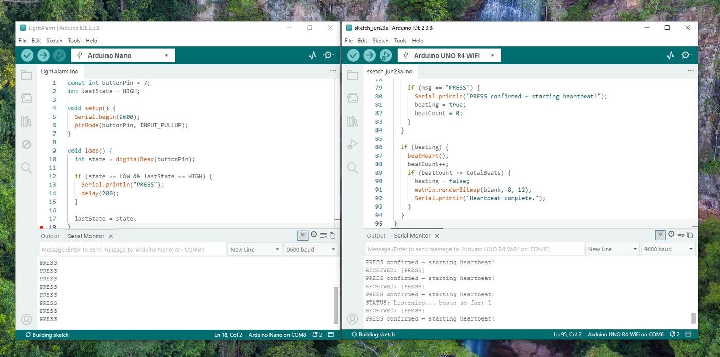
With both boards connected and sketches uploaded, pressing the button triggered the full sequence reliably: the Nano sent "PRESS", the UNO R4 received it, printed "PRESS confirmed — starting heartbeat!" in the Serial Monitor, and the LED matrix ran the 5-beat animation at 72 BPM before clearing.
What the Serial Monitor showed
Nano side: Serial.println("PRESS") called on each button press — visible in its own monitor.
UNO R4 side:
RECEIVED: [PRESS]
PRESS confirmed — starting heartbeat!
STATUS: Listening... beats so far: 1
Heartbeat complete.
Problems & How I Fixed Them
TX/RX Wiring — Communication Only Worked One Way
My first instinct was to wire both TX and RX between the boards — cross-connecting TX to RX and RX to TX on each side, as you would for full two-way serial. But the UNO R4 received nothing. After stepping back, I realised the communication here is one-way: the Nano only sends, the UNO R4 only receives. So the Nano's TX pin was fighting the UNO R4's TX pin on the same line, which caused the signal to conflict.
The fix was to remove the RX→TX wire entirely and use only a single wire:
Final Wiring
Nano pin 1 (TX) ───────→ pin 0 (RX1) UNO R4
Nano GND ───────── GND UNO R4
One TX wire + shared GND is all that's needed for one-directional serial. The UNO R4 never needs to send anything back to the Nano, so the RX side of the Nano can stay disconnected.
Button Sending Multiple Messages Per Press
A single press was triggering 3–4 transmissions due to switch bounce. I tracked lastState so the message only fires on the HIGH → LOW transition, not while the button stays held, and added a 200ms delay after each send as a simple software debounce.
What I Learned
The shift from standalone to networked thinking. Every week before this, everything happened on one board. This week the input and output were physically separated, which forced me to think about the system differently — the Nano doesn't know what the UNO R4 does with the message, and the UNO R4 doesn't know what triggered it. That loose coupling is what makes communication protocols useful.
Hardware UART details matter. The difference between Serial and Serial1 on the UNO R4 caused my first hour of debugging. It's a detail that's easy to miss if you assume all serial ports are the same, but once you understand that Serial is USB-only and Serial1 is the hardware TX/RX pins, the wiring makes much more sense.
What I'd do differently: I'd explore I²C next — it's cleaner for multi-device setups since it only needs two wires regardless of how many devices are on the bus. For this project wired serial was perfectly fine, but I²C would scale better if I wanted to add a third device.