Assignment Tasks
🔬 Group Assignment
- Measure the power consumption of an output device
- Document on the group work page and reflect individually on what you learned
👤 Individual Assignment
- Add an output device to a microcontroller board you've designed and program it to do something
Introduction
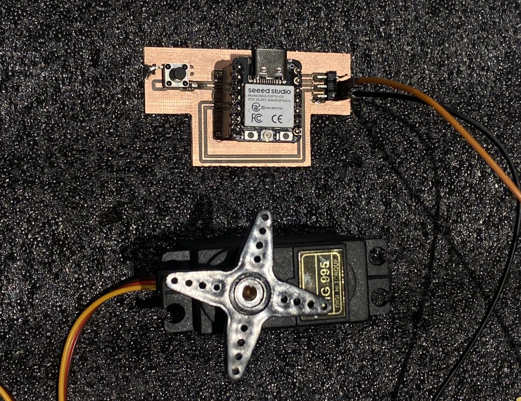
For this week's assignment, I extended my custom PCB design to include a servo motor as an output device, controlled by an SMD push button as the input. The system is built around the Seeed XIAO ESP32-C3, the same microcontroller I used in Week 9. Each press of the button rotates the servo by 10 degrees, allowing precise incremental position control.
This builds directly on my Week 9 work — where I established the button-to-LED input/output loop — and adds a mechanical output dimension to the design.
Components & Tools
| Component / Tool | Details |
|---|---|
| Microcontroller | Seeed XIAO ESP32-C3 |
| Output device | Servo motor |
| Input | SMD tactile push button |
| Design software | KiCad |
| Programming IDE | Arduino IDE |
| Library | ESP32Servo |
| Button pin | D1 (INPUT_PULLUP) |
| Servo pin | D3 (PWM) |
What is a Servo Motor?
A servo motor is a rotary actuator that enables precise angular position control. Unlike a standard DC motor that spins continuously, a servo receives a PWM (Pulse Width Modulation) signal and moves to a specific angle — typically in the range of 0° to 180°. This makes servos ideal for applications requiring controlled, repeatable mechanical movement such as robotic joints, camera gimbals, and smart fixtures.
What is PWM (Pulse Width Modulation)?
PWM is a technique for encoding information in a pulsed signal by varying the duty cycle — the proportion of time the signal is HIGH versus LOW within each period. For servo motors, the pulse width (typically 1ms–2ms within a 20ms period) directly maps to a specific angle. The ESP32-C3 generates this signal in hardware, making servo control straightforward with the ESP32Servo library.
Power Consumption — Group Assignment
As part of the group assignment, we measured the power consumption of an output device using a multimeter in series with the circuit. The full methodology, measurements, and results are documented on Sarah's group assignment page.
What I Learned from the Group Work
Measuring power consumption made me much more deliberate about component selection. Servo motors draw significantly more current than LEDs — especially under load — which means power budgeting is critical for battery-powered designs. I also learned that current draw varies with mechanical load: an unloaded servo draws minimal current, while a stalled or heavily loaded servo can draw several times more.
Step-by-Step Documentation
Component Selection
Before designing the PCB, I selected the components needed for this output device project: a servo motor as the mechanical actuator and an SMD tactile push button as the user input.
| Component | Spec | Why it was chosen |
|---|---|---|
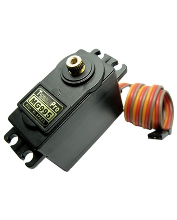
| TowerPro MG995 Servo | 4.8–7.2V, metal gear, 0°–180° | Metal gears for durability; digital control for precise 10° steps; directly relevant to final project actuation needs |
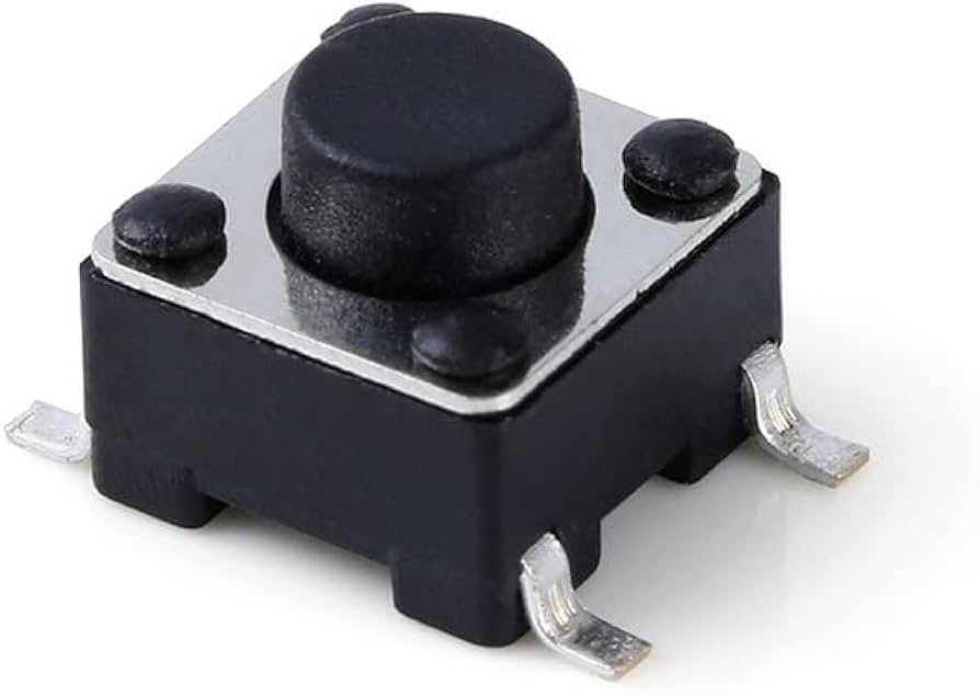
| SMD Tactile Button | 4-pin, surface-mount | Compact footprint, easy to route in KiCad, same button type proven in W09 design |
| Seeed XIAO ESP32-C3 | PWM on all GPIO, 3.3V logic | Reused from W09; ESP32Servo library handles PWM generation in hardware |
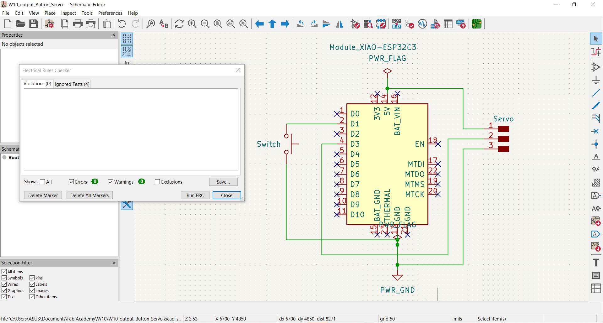
Schematic Design in KiCad
I designed the schematic in KiCad, expanding on the W09 board layout to add a servo motor connector. The XIAO ESP32-C3 drives the servo via its D3 PWM pin, while the SMD button on D1 remains as the user input.
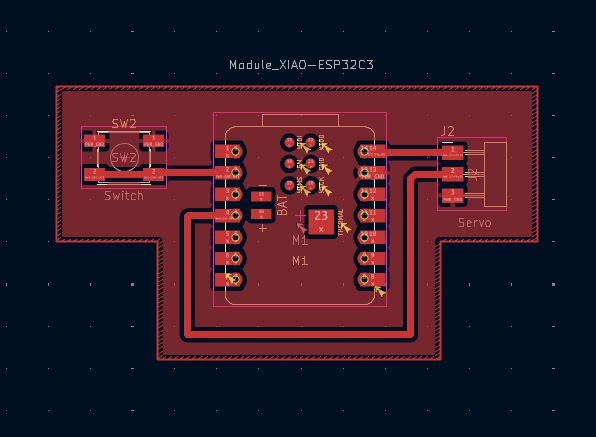
PCB Layout in KiCad
Fabrication & Soldering
After exporting Gerber files from KiCad, the PCB was fabricated and then populated with components. The SMD button was soldered first, followed by the servo connector and the XIAO ESP32-C3 module.
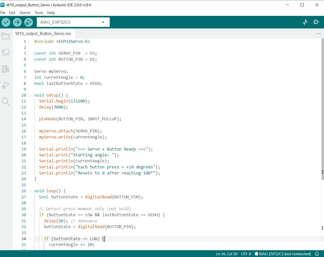
Firmware — Arduino IDE
The firmware was written in Arduino IDE using the ESP32Servo library. Each button press increments the servo angle by 10°, resetting to 0° after 180°. Structured Serial.println() logging traces every cycle for verification.
#include <ESP32Servo.h>

const int SERVO_PIN  = D3;
const int BUTTON_PIN = D1;

Servo myServo;
int currentAngle = 0;
int cycleCount   = 0;
bool lastButtonState = HIGH;

void setup() {
  Serial.begin(115200);
  pinMode(BUTTON_PIN, INPUT_PULLUP);
  myServo.attach(SERVO_PIN);
  myServo.write(currentAngle);
}

void loop() {
  bool buttonState = digitalRead(BUTTON_PIN);

  if (buttonState == LOW && lastButtonState == HIGH) {
    delay(50); // debounce
    if (digitalRead(BUTTON_PIN) == LOW) {
      cycleCount++;
      currentAngle += 10;
      if (currentAngle > 180) currentAngle = 0;

      Serial.print("[CYCLE "); Serial.print(cycleCount);
      Serial.println("] Button State: PRESSED (D1 = LOW)");
      Serial.print("[ACTION] Servo moving to ");
      Serial.print(currentAngle); Serial.println("°");
      myServo.write(currentAngle);
      Serial.print("[STATUS] Button PRESSED --> Servo at ");
      Serial.print(currentAngle); Serial.println("°");
      Serial.println("[INFO]   Waiting for next press...");
      Serial.println();
    }
  }

  lastButtonState = buttonState;
  delay(10);
}ESP32Servo library required: The standard Arduino Servo.h is not compatible with the ESP32. Install ESP32Servo via Arduino IDE → Tools → Manage Libraries before compiling.
Serial Monitor Output
Opening the Serial Monitor at 115200 baud shows each press cycle with its angle update. The output below captures two consecutive presses:
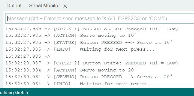
Each cycle takes ~2 seconds between presses (27.939 → 29.987), confirming clean edge detection with no phantom triggers between presses.
Testing & Results
After uploading the firmware, I tested the board by pressing the button repeatedly to verify:
- Each press rotates the servo exactly 10°.
- The servo holds its position between presses.
- After 18 presses (reaching 180°), the next press resets the servo to 0°.
- No unintended movement occurs when the button is not pressed.
All conditions were satisfied. The servo responded smoothly and consistently, with no jitter between presses — confirming that the PWM signal and edge-detection logic are working correctly.
Demo Video
The video below shows the servo rotating 10° with each button press.
Understanding the Servo Motor as an Output Device
How It Works Physically
A servo motor moves to a specific angle and holds it. Send it a signal → it rotates to that position and stays there until told otherwise.
PWM Signal — Digital Control of an Analog Output
The servo receives a digital PWM signal but produces a smooth, continuous physical rotation — making it a bridge between the digital and physical world. The pulse width within each 20 ms period directly maps to a target angle.
Pulse Width → Angle mapping
1.0 ms pulse = 0° · 1.5 ms pulse = 90° · 2.0 ms pulse = 180°. The ESP32Servo library handles this translation — calling myServo.write(90) automatically generates the correct 1.5 ms pulse.
Physical Input vs Measured Output
| Property | Value | Notes |
|---|---|---|
| Control signal | PWM — digital | 50 Hz, 1–2 ms pulse width |
| Angular range | 0° – 180° | Limited by mechanical stop inside servo |
| Step resolution | ~1° (firmware uses 10°) | Library supports 1° increments |
| No-load current | ~150–200 mA @ 5V | Idle while holding position |
| Stall current | up to 1.2 A @ 5V | When blocked from reaching target |
| Position feedback | Internal — not readable by MCU | Servo handles its own feedback loop |
Expected Range & Limitations
- Mechanical stops: Going beyond 0° or 180° physically damages the internal gearbox. The firmware resets to 0° after 180° to prevent this.
- Power supply: Servos draw much more current than LEDs — they must be powered from a 5 V rail with enough capacity, not directly from the ESP32's 3.3 V logic pin.
- Signal voltage: The servo control signal accepts 3.3 V logic from the ESP32, but the motor itself runs on 5 V — the two power rails are separate.
- No position readback: Unlike stepper motors, a standard servo doesn't report its current angle back to the microcontroller. If the servo is physically blocked, the MCU has no way to detect a stall.
The Serial Monitor output confirms clean output behavior: each [CYCLE] prints before the move command, and [STATUS] prints after myServo.write() returns — confirming the angle was set before the log line appears.
Problems Encountered & How They Were Resolved
1 — Wrong Servo Library (Compile Error)
Initially I used the standard #include <Servo.h> library, which produced a compile error: "Servo.h: No such file or directory" on the ESP32 target. Switching to #include <ESP32Servo.h> and installing the ESP32Servo library via the Library Manager resolved this immediately.
Design Files & Source Code
| File | Description |
|---|---|
| W10_output_Button_Servo_KiCAD.zip | Full KiCad project (ZIP) |
w10-servo-button.ino | Arduino sketch (firmware — reproduced above) |
Design files are committed to the repository alongside this documentation. The full source code is reproduced in the Code section above.
Reflection
This week extended my understanding of microcontroller programming from simple on/off outputs (the LED in W09) to position-controlled mechanical actuation. The servo motor introduces a richer interaction model: rather than a binary state, you're controlling a continuous physical parameter — angle — with precision.
The edge-detection pattern for the button (detecting HIGH→LOW transitions rather than just reading the current state) is a technique I'll use in my final project. It's a clean, software-only way to treat a physical button as an event trigger rather than a continuous input.
The power consumption measurement from the group assignment also changed how I think about output device selection. This needs to be factored into PCB design decisions — especially trace widths and power supply sizing. For my final project, this means I need to ensure the power rail can sustain the peak current without causing voltage drops that could reset the microcontroller.