Assignment Tasks
🔬 Group Assignment
- Probe an input device's analog levels and digital signals using a multimeter and an oscilloscope
👤 Individual Assignment
- Measure something — add a sensor to a microcontroller board that you have designed and read it
Introduction
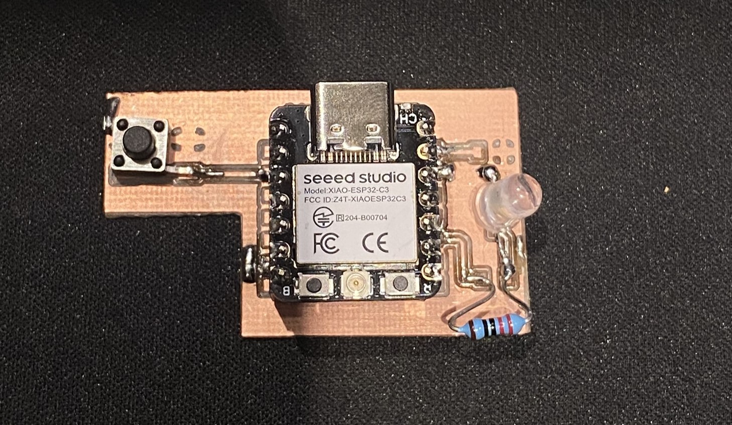
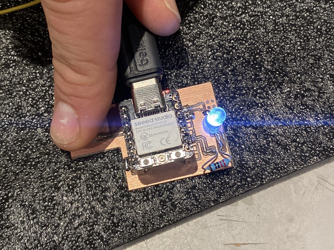
For this week's assignment, I designed a custom PCB that incorporates a push button as an input device and an LED as a visual output indicator. The goal was to build a complete input–output system from scratch — designing the schematic and layout in KiCad, fabricating the board, soldering the components, and writing firmware that reads the button state and responds by toggling the LED.
This exercise builds directly on my earlier work in electronics design and production, allowing me to integrate input sensing into a self-designed board rather than relying on a development kit. It also pushes toward my final project, which involves a smart light fixture where user inputs control lighting behavior.
Components & Tools
| Component / Tool | Details |
|---|---|
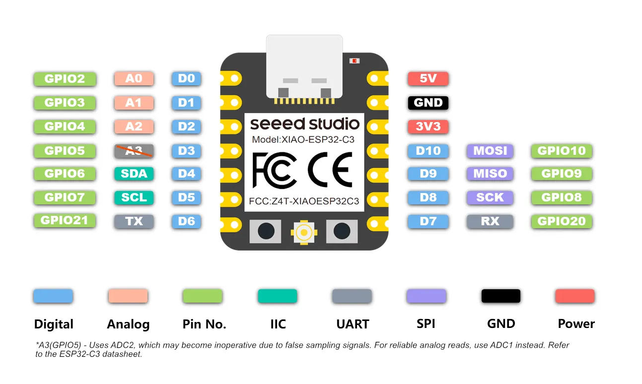
| Microcontroller | Seeed XIAO ESP32-C3 |
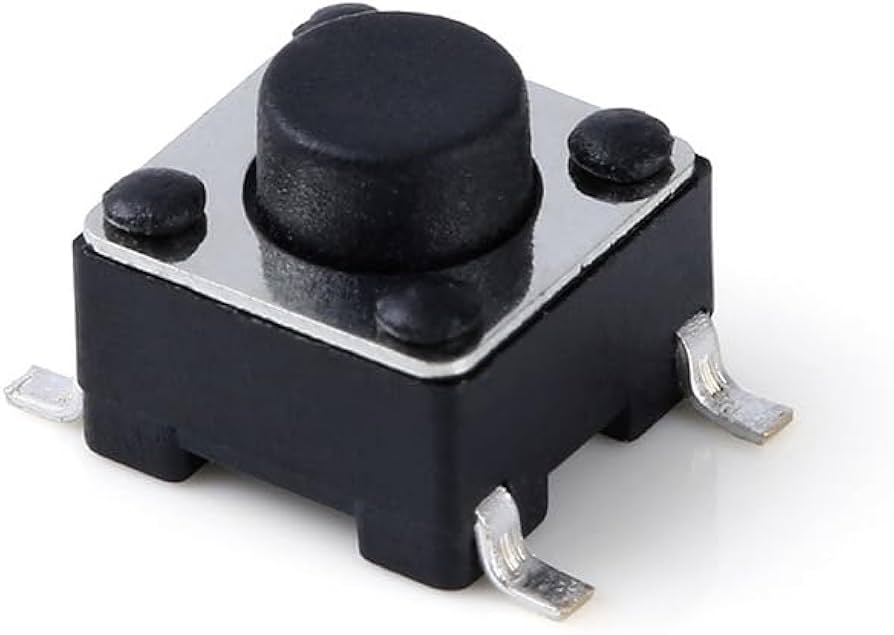
| Input device | SMD tactile push button |
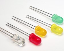
| Output indicator | Through-hole LED |
| Design software | KiCad |
| Programming IDE | Arduino IDE |
| Pin assignments | Button → D1, LED → D9 |
Step-by-Step Documentation
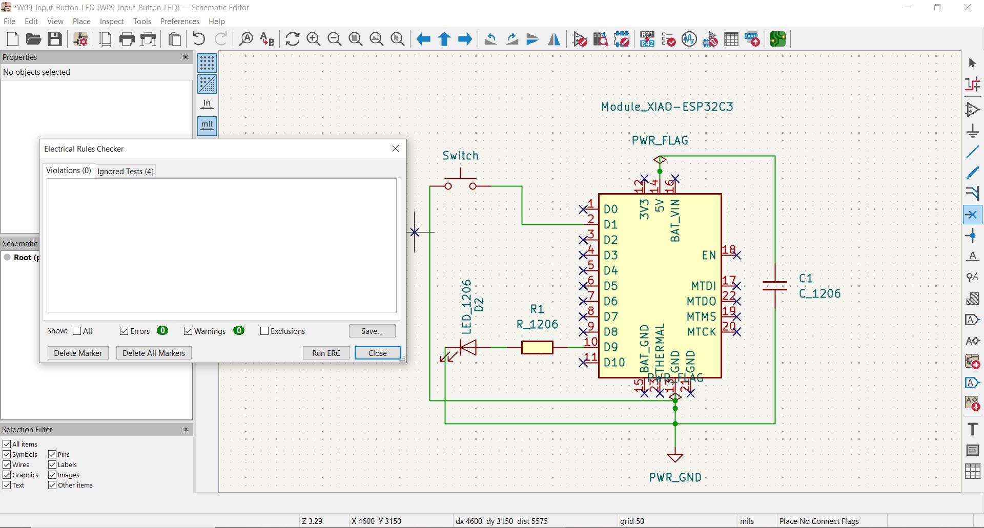
Schematic Design in KiCad
I started by designing the circuit in KiCad. The design centers on the Seeed XIAO ESP32-C3, chosen for its compact footprint, built-in Wi-Fi/Bluetooth capabilities, and compatibility with the Arduino ecosystem. For this assignment I used only its GPIO functionality, but the wireless capability will be relevant for my final project.
The schematic includes:
- A tactile SMD push button on pin D1.
- A through-hole LED on pin D9, with a current-limiting resistor to prevent overcurrent damage to both the LED and the microcontroller.
Component Selection
I chose a through-hole LED for ease of soldering and visual clarity, and an SMD tactile button to practice working with surface-mount components.
PCB Layout & Fabrication
With the schematic complete, I moved to the PCB layout design phase in KiCad.
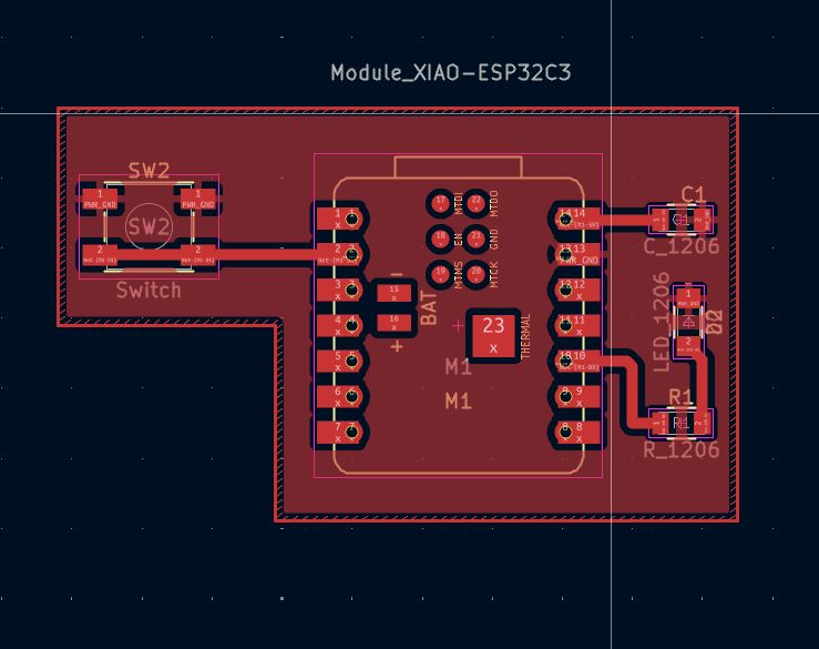
Key layout decisions: button placed at the board edge for easy thumb access; 0.8 mm trace widths for signal lines; ground fill on the bottom copper layer to reduce noise and simplify routing.
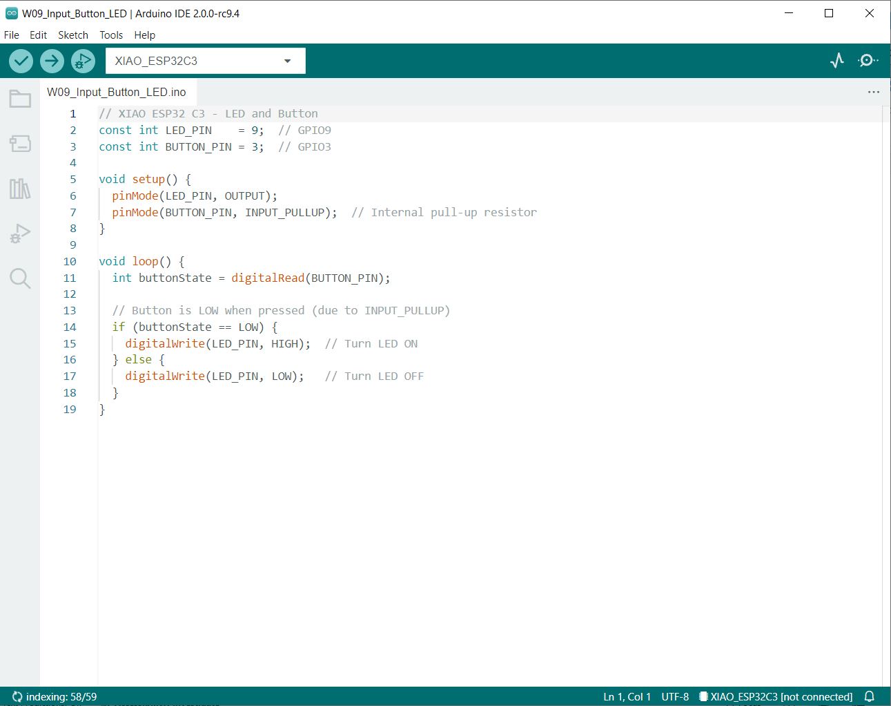
Firmware — Arduino IDE
The firmware was written in the Arduino IDE using the ESP32-C3's Arduino-compatible environment. It polls the button state on every loop cycle and mirrors it to the LED — with structured Serial.println() logging added so each state transition is visible in the Serial Monitor for verification.
// XIAO ESP32-C3 — Button Input / LED Output with Serial logging
const int LED_PIN    = 9;   // GPIO9  → D9
const int BUTTON_PIN = 3;   // GPIO3  → D1
int lastState = HIGH;       // tracks previous button state

void setup() {
  Serial.begin(115200);
  pinMode(LED_PIN, OUTPUT);
  pinMode(BUTTON_PIN, INPUT_PULLUP);  // pull-up: HIGH at rest, LOW when pressed
}

void loop() {
  int currentState = digitalRead(BUTTON_PIN);

  if (currentState == LOW && lastState == HIGH) {
    // Button just pressed
    Serial.println("[INPUT]  Button State: PRESSED (GPIO3 = LOW)");
    Serial.println("[ACTION] Writing HIGH to LED_PIN (GPIO9)");
    digitalWrite(LED_PIN, HIGH);
    Serial.println("[STATUS] LED --> ON");
    Serial.println("[INFO]   Holding button for 2 seconds...");
    delay(2000);
  }

  if (currentState == HIGH && lastState == LOW) {
    // Button just released
    Serial.println("[INPUT]  Button State: RELEASED (GPIO3 = HIGH)");
    Serial.println("[ACTION] Writing LOW to LED_PIN (GPIO9)");
    digitalWrite(LED_PIN, LOW);
    Serial.println("[STATUS] LED --> OFF");
    Serial.println("[INFO]   Button idle for 2 seconds...");
    delay(2000);
  }

  lastState = currentState;
}
Serial Monitor Output
Opening the Serial Monitor at 115200 baud shows the exact state transitions in real time. The output below is captured from a live button press-and-release cycle:
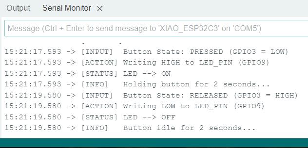
The timestamps confirm the button was held for exactly 1.987 seconds (17.593 → 19.580), and every transition — read, write, and status — is logged in sequence with no missed events.
Testing & Results
After uploading the firmware, I tested the board by pressing and releasing the button repeatedly to confirm:
- The LED illuminates immediately when the button is pressed.
- The LED turns off cleanly when the button is released.
- No false triggers occur when the button is not pressed.
- Behaviour is consistent across multiple press cycles.
All four conditions were satisfied. The response felt instantaneous — confirming that the INPUT_PULLUP configuration and polling-based loop are sufficient for this interaction speed.
Demo Video
The following video demonstrates the board in operation: pressing the button illuminates the LED, releasing it turns the LED off.
Understanding the Push Button as a Sensor
How It Works Physically
A push button is a simple on/off switch — pressing it connects two contacts and completes the circuit; releasing it breaks the connection. It only tells you two things: pressed or not pressed.
Digital Signal Behavior — INPUT_PULLUP
Without anything connected, a GPIO pin reads random noise. A pull-up resistor fixes this by holding the pin HIGH by default. When the button is pressed and pulls the pin to GND, the signal drops to LOW — giving a clean, stable reading.
Why the logic is inverted
With INPUT_PULLUP: the pin reads HIGH (1) at rest and LOW (0) when pressed. This is the opposite of what feels intuitive — "pressed" returns 0, not 1. The firmware checks if (buttonState == LOW) to detect a press precisely because of this inversion.
Analog vs Digital Signal
| Property | This Button (Digital) | Analog Sensor (e.g. potentiometer) |
|---|---|---|
| Output type | Discrete — HIGH or LOW | Continuous — 0 to 3.3 V range |
| Values | 2 states only (0 or 1) | 0–4095 (12-bit ADC resolution) |
| Read function | digitalRead(pin) | analogRead(pin) |
| Noise sensitivity | Low (binary threshold) | High (susceptible to float/drift) |
| Pull-up needed? | Yes — prevents floating | No — signal is actively driven |
Expected Range & Limitations
- Voltage range: 0 V (pressed) to 3.3 V (released). The ESP32-C3 GPIO threshold is approximately 1.65 V — anything below is LOW, above is HIGH.
- Contact bounce: When a mechanical button is pressed or released, the contacts physically bounce for 1–10 ms, causing rapid HIGH/LOW oscillations before settling. The
delay(2000)in the code effectively masks this but is far longer than needed — a proper debounce uses a 20–50 ms delay or interrupt-based edge detection. - Current draw: With
INPUT_PULLUPactive and button pressed, the GPIO sources a small current through the internal pull-up resistor (~40–50 kΩ) to GND — roughly 66–83 µA, well within safe limits. - Mechanical lifetime: SMD tactile buttons are typically rated for 100,000–300,000 actuations before contact wear becomes a reliability concern.
The Serial Monitor output confirms the digital nature of the input: the button transitions directly from RELEASED (GPIO3 = HIGH) to PRESSED (GPIO3 = LOW) with no intermediate values — exactly the binary behavior expected from a digital switch read with digitalRead().
Design Files & Source Code
| File | Description | Download |
|---|---|---|
W09_Input_Button_LED_KiCAD.zip |
Full KiCad project (schematic, PCB, BOM, netlist) | ⬇ Download |
The Arduino firmware is fully reproduced in the Code section above. All KiCad design files are available for download above.
Reflection
This assignment made concrete something I had understood only theoretically: designing the schematic, laying out the PCB, fabricating it, soldering it, and then writing code that makes a physical LED respond to a physical button press gives a deeply satisfying sense of the whole system.
My final project is a smart light fixture where user inputs control lighting behaviour. The button-to-LED circuit built here is a simplified version of that user-input subsystem. This week consolidated the electronics design and production skills from Weeks 6 and 8 — I now feel capable of designing a board that integrates sensors, writing firmware that reads and reacts to them, and debugging the result systematically.