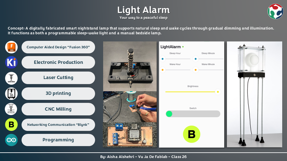
About the Project
Sleep has always been something I struggle with. Falling asleep rarely happens naturally for me, and most nights I find myself lying awake while my mind keeps racing. I noticed that the environment around me — especially harsh lighting and the habit of using my phone late at night — makes it even harder for my body to slow down and prepare for rest.
Because of this personal struggle, I wanted my final project to focus on creating something that could gently support a healthier nighttime routine. The smart nightstand lamp helps the body gradually transition between wakefulness and sleep, working in harmony with the body's circadian rhythm instead of fighting it. Rather than relying on sudden darkness at night or an abrupt alarm in the morning, the lamp simulates a sunset at bedtime and a sunrise at wake-up — both scheduled automatically through a companion mobile app.
Prior Art — Who Has Done Similar Work?
Philips SmartSleep Wake-up Light
A sunrise alarm lamp that gradually brightens over 30 minutes before the set wake time. Uses fixed, closed firmware with no customizable sunset simulation or Wi-Fi connectivity.
Casper Glow Light
A Wi-Fi connected bedside lamp with gentle dimming and sunrise features. Limited to a companion app without physical toggle control or DIY customization.
My project differentiates itself by being entirely self-fabricated — from the PCB milled at the lab to the 3D-printed enclosure — and by using a physical toggle switch as the primary mode selector rather than relying exclusively on a phone.
How It Works
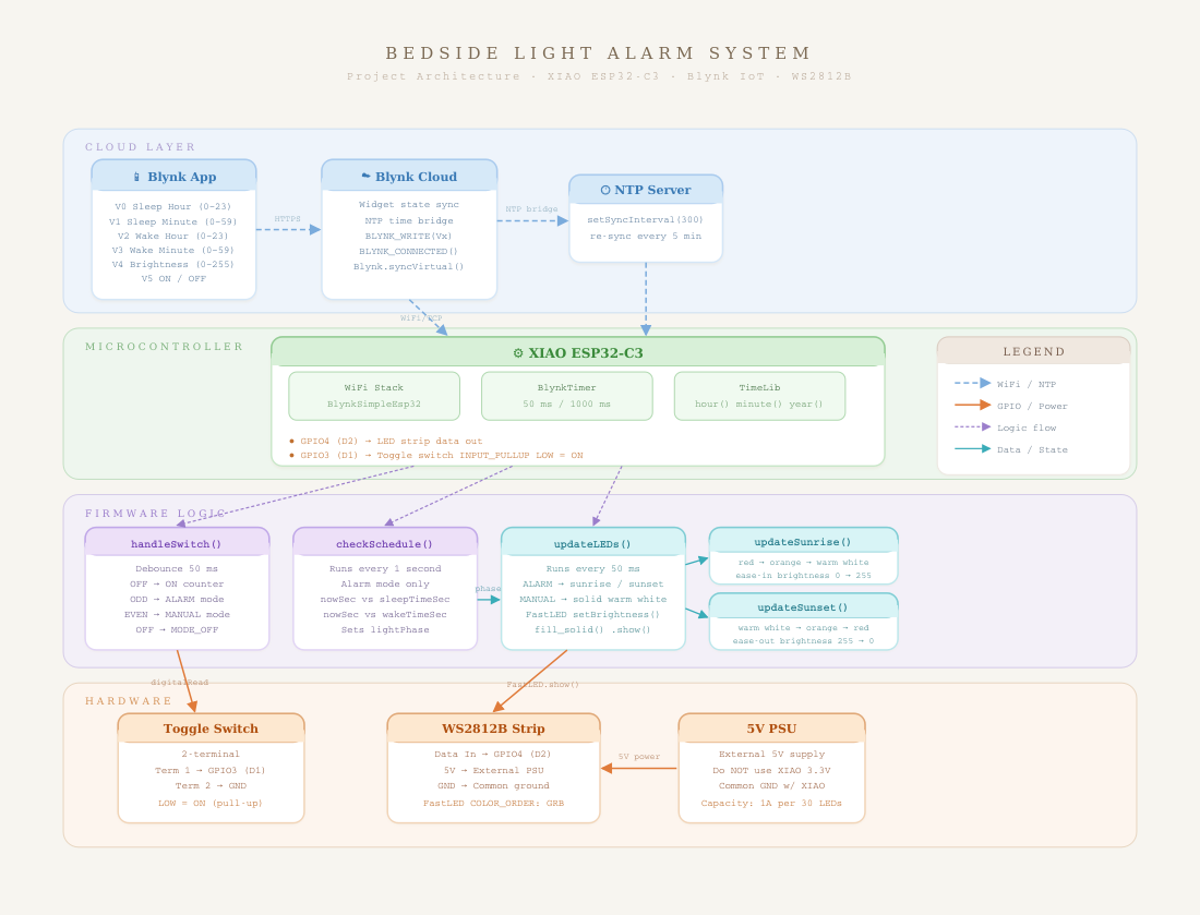
The lamp is operated by a single physical toggle switch, which selects between two modes. Toggling it once activates the Smart Light Alarm Mode. Toggling it off and back on switches into Manual Mode. The Blynk mobile app is used to set schedules and adjust brightness, depending on the active mode.
Night Mode — Wind Down
- Lamp slowly dims as bedtime approaches
- Produces a warm sunset light effect
- Fades completely to off, encouraging natural sleep onset
- Schedule set via app — brightness & color locked in this mode
Morning Mode — Wake Up
- Light gradually increases from zero to full brightness
- Simulates a gentle sunrise instead of a harsh alarm
- Helps the user wake up naturally and calmly
- Runs automatically every day at the scheduled wake time
Manual Mode
- →Toggle switch off then on again to activate
- →Light turns on instantly at full brightness
- →Full brightness control from the app
- →Daily schedule is paused in this mode
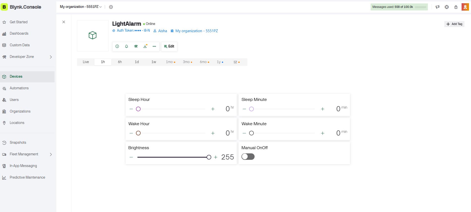
App Control (Blynk)
- →Set sleep time and wake-up time
- →Adjust brightness slider in manual mode
- →Communicates via Wi-Fi (ESP32-C3)
- →Dashboard built on Blynk IoT platform
Project Specifications
Category
Smart Wellness Device
Input
Toggled switch (two modes) + Blynk mobile app (schedule & brightness)
Output
WS2812B addressable LED strip
Microcontroller
Seeed Studio XIAO ESP32-C3
Fabrication
3D Printing · Laser Cutting · PCB Milling
Connectivity
Wi-Fi (Blynk IoT platform)
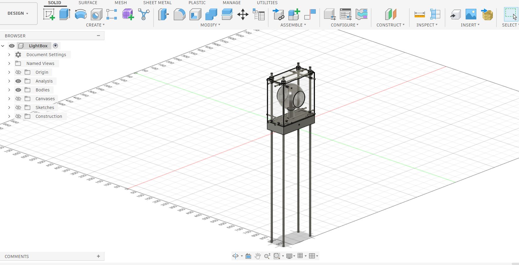
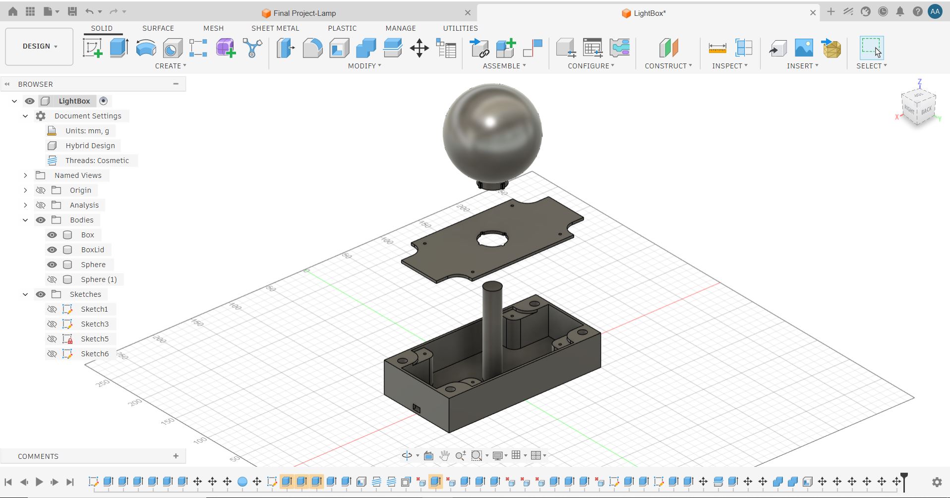
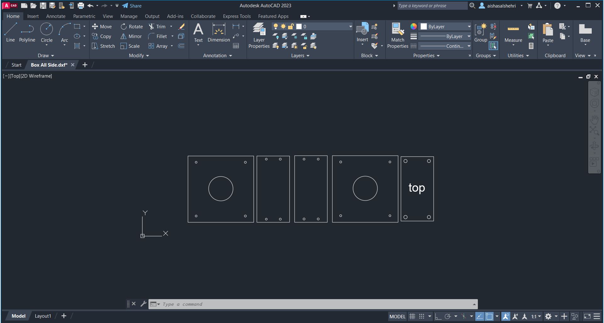
Concept & CAD Design
I used computer-aided design to take the lamp to a manufacturable form. Fusion 360 was used for full 3D modeling of the assembly, and AutoCAD was used to prepare the 2D panel layout for laser cutting.
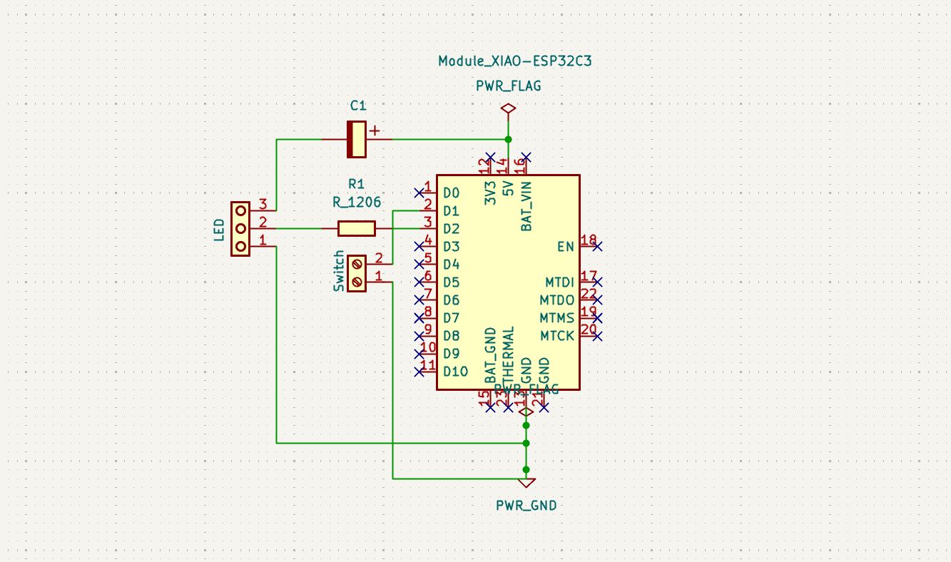
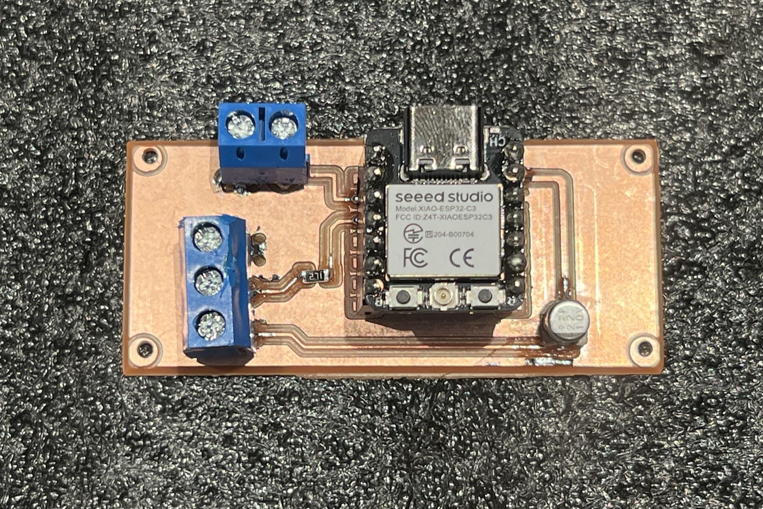
Electronics Design & PCB
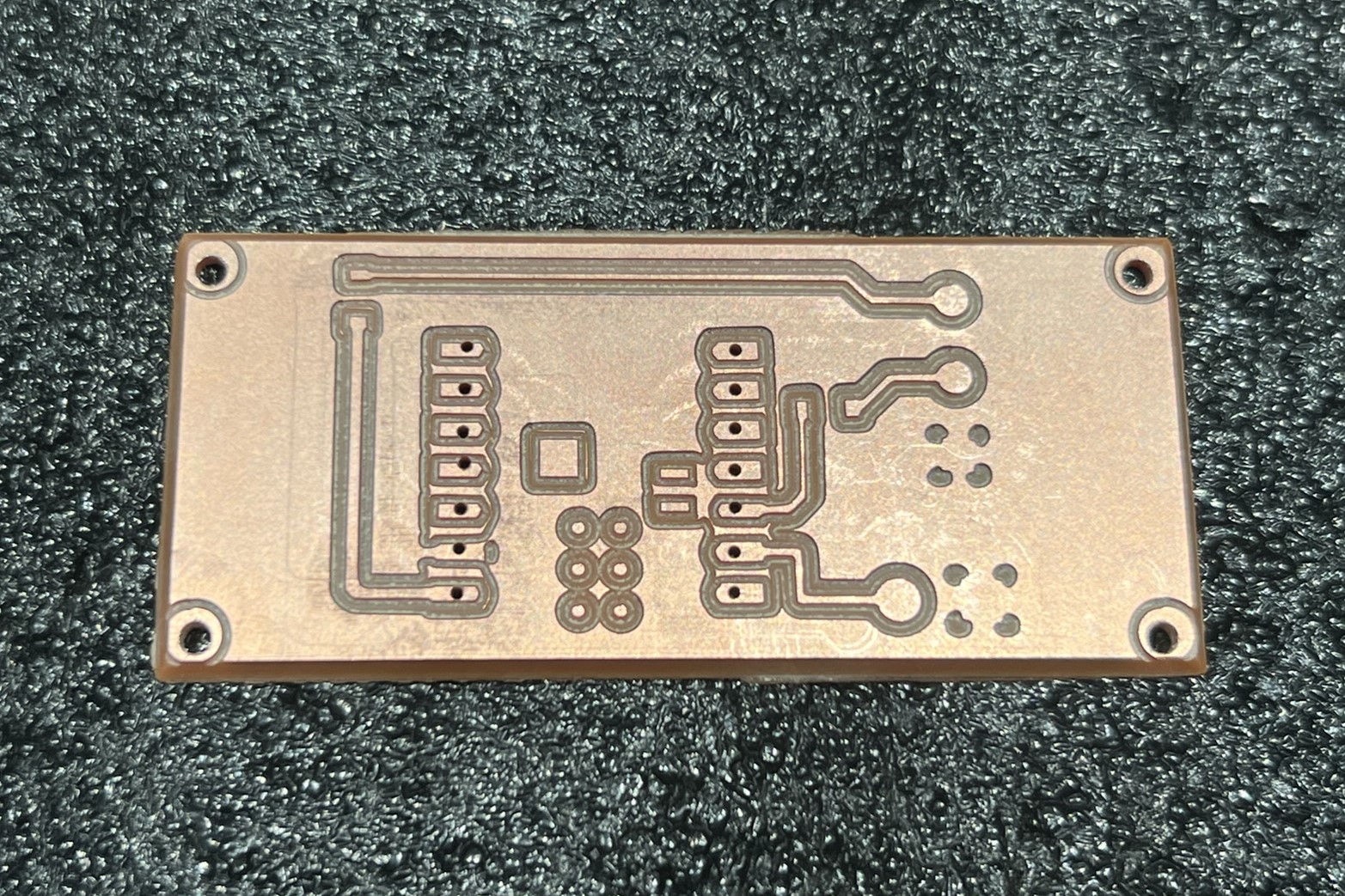
Before committing to a custom board, I prototyped and validated the circuit on a breadboard. Once the logic was confirmed, I designed a dedicated single-layer PCB in KiCad.
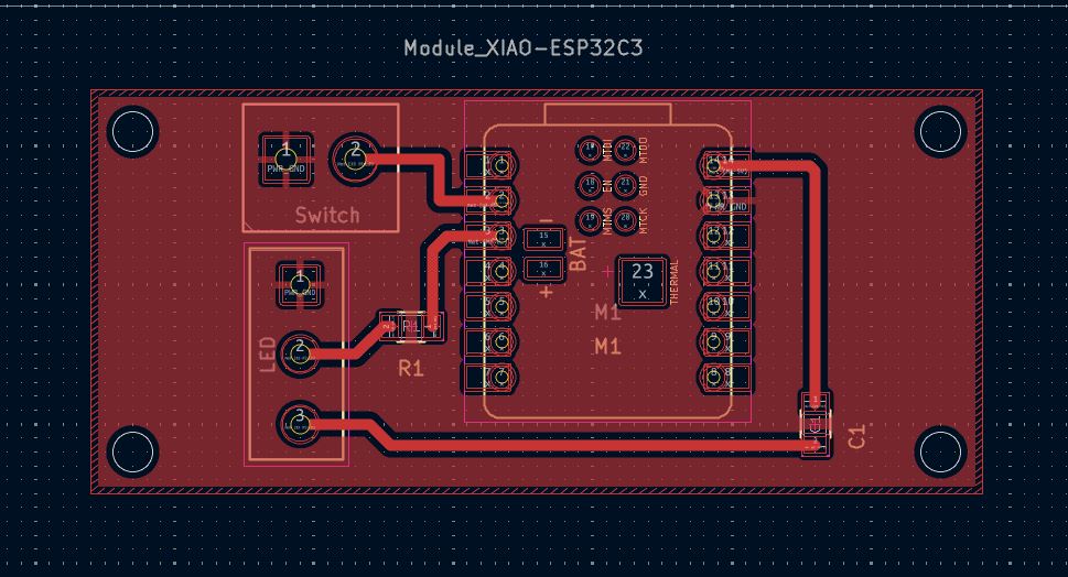
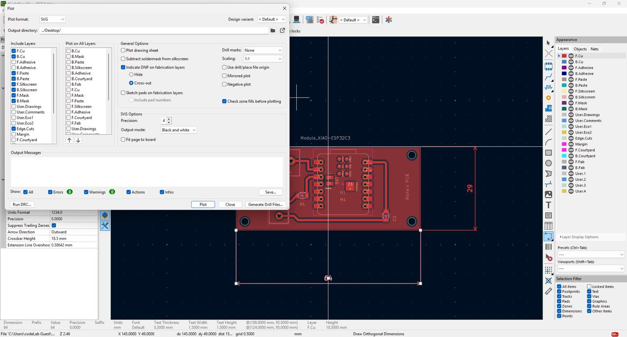
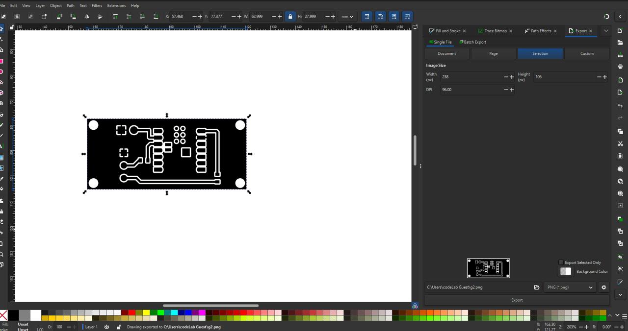
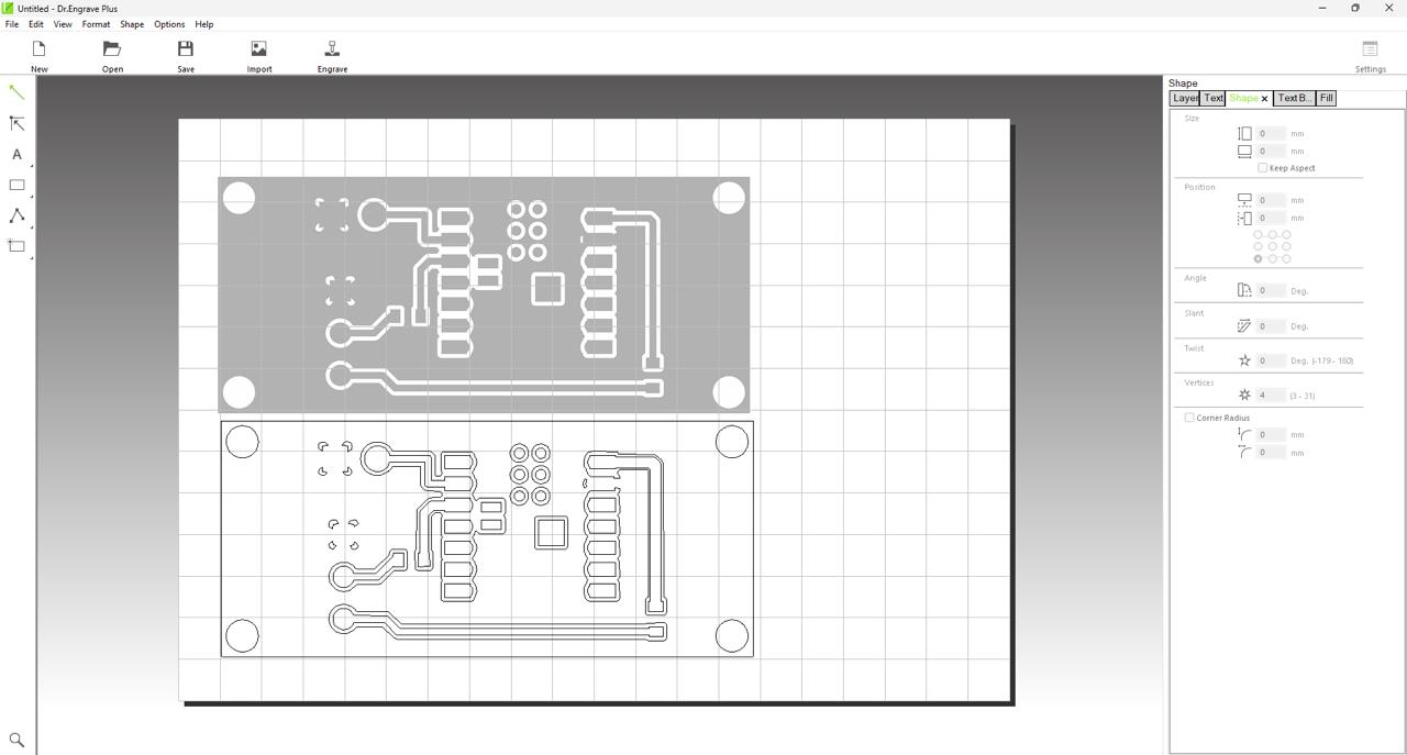
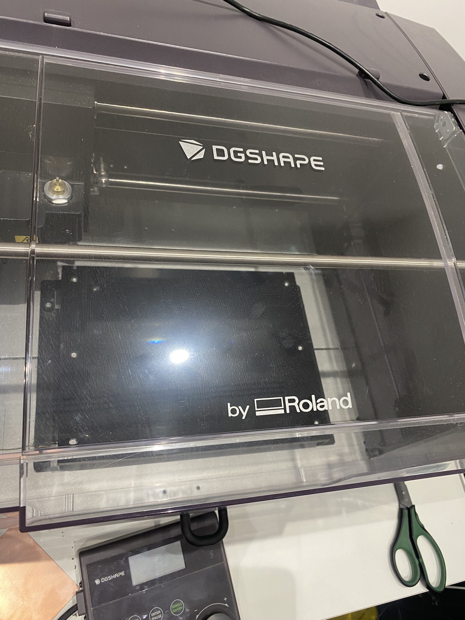
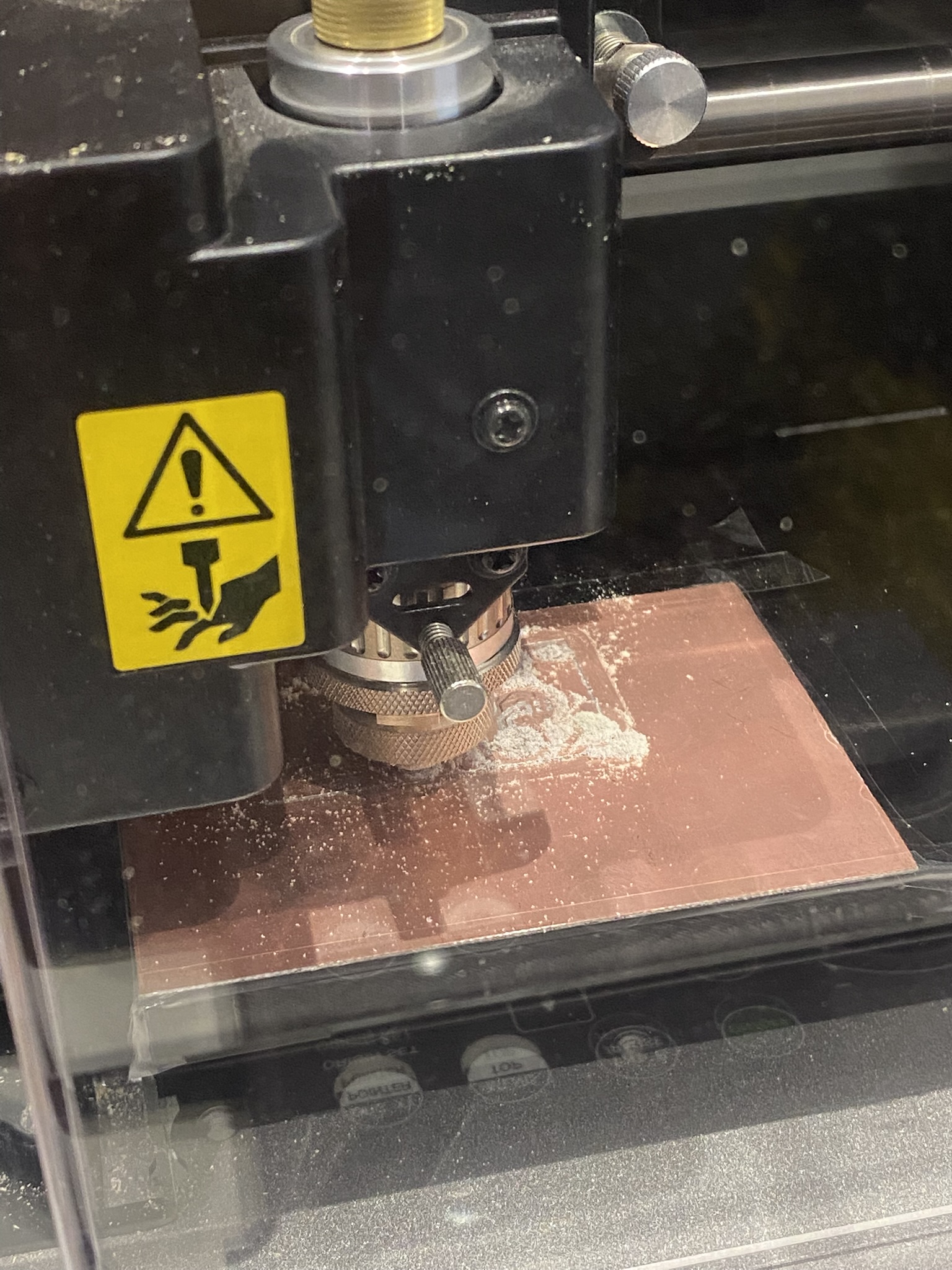
PCB Fabrication — CNC Milling
The PCB was fabricated using a DGshape by Roland CNC milling machine. The workflow: export the board from KiCad as SVG with the copper layer selected → import into Inkscape to convert to a high-resolution bitmap → load into Dr. Engraver Plus to generate G-code for the mill.
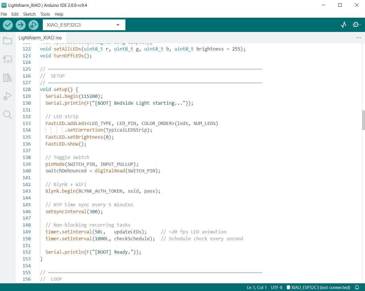
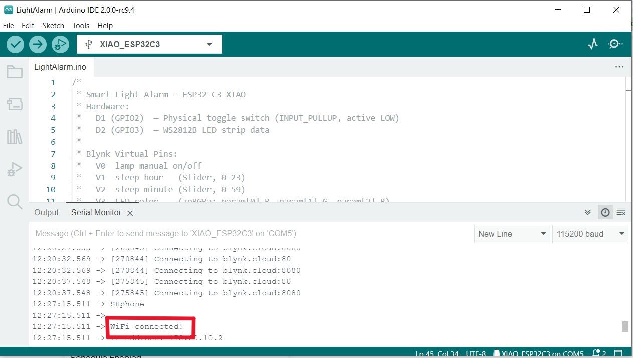
Embedded Programming
The firmware was written in Arduino IDE and flashed to the XIAO ESP32-C3. The microcontroller connects to Wi-Fi and communicates with the Blynk IoT platform, where the user's schedule and brightness settings are stored and pushed to the device in real time.
Manual Mode: Flip the switch off then back on. The LED strip turns on immediately at full brightness. A slider in the Blynk app lets the user adjust brightness freely. The automatic schedule is paused.
Blynk App Dashboard
I built the companion dashboard in the Blynk web interface — see Week 14 for the detailed step-by-step setup. The dashboard includes a time-picker for sleep and wake schedules and a brightness slider for manual mode. After building the dashboard, I linked the Blynk virtual pins to the Arduino sketch and tested the connection over Wi-Fi.
.jpeg)
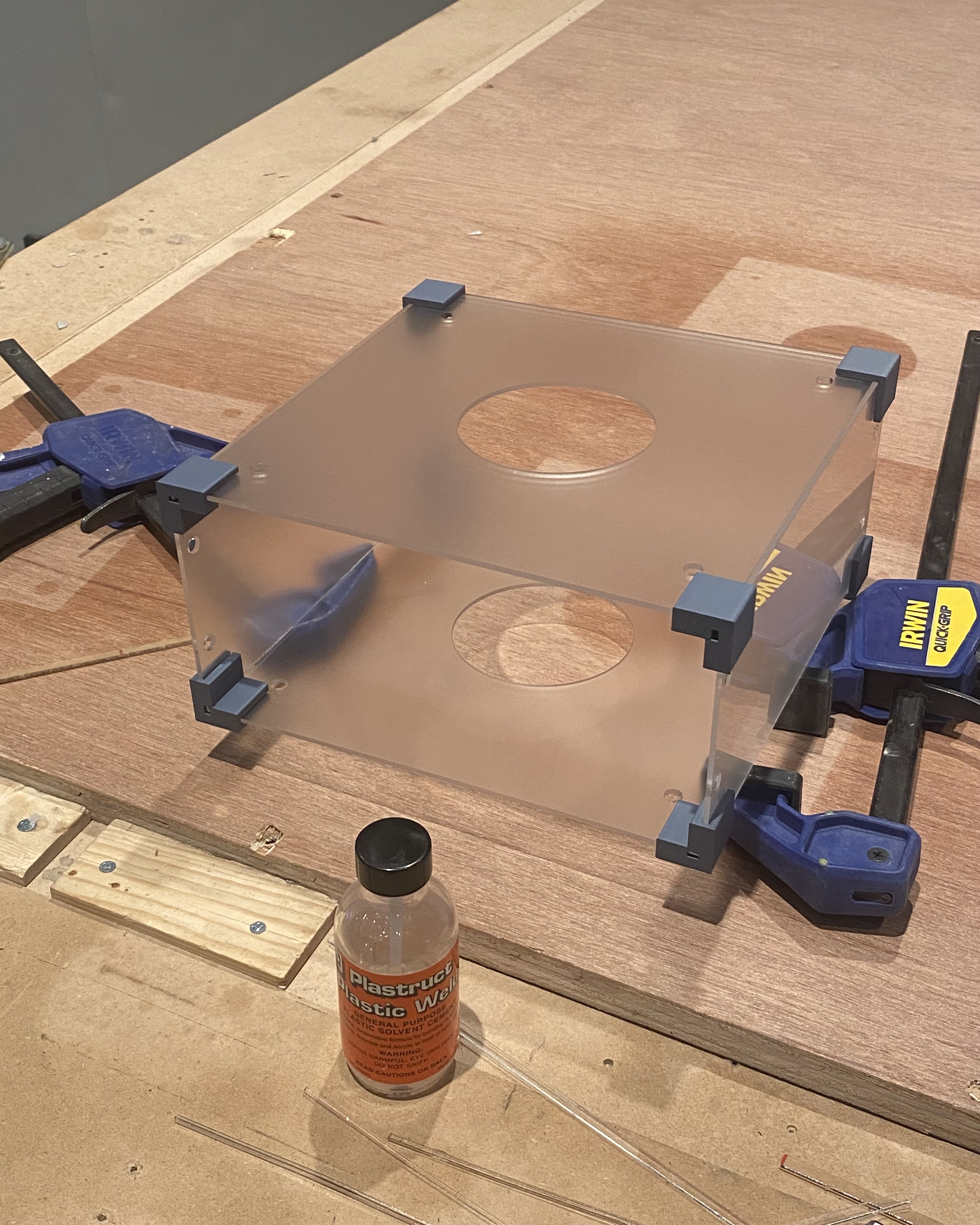
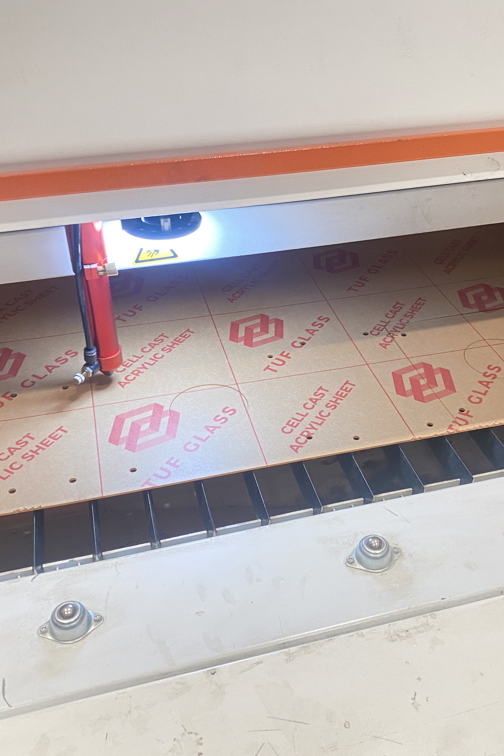
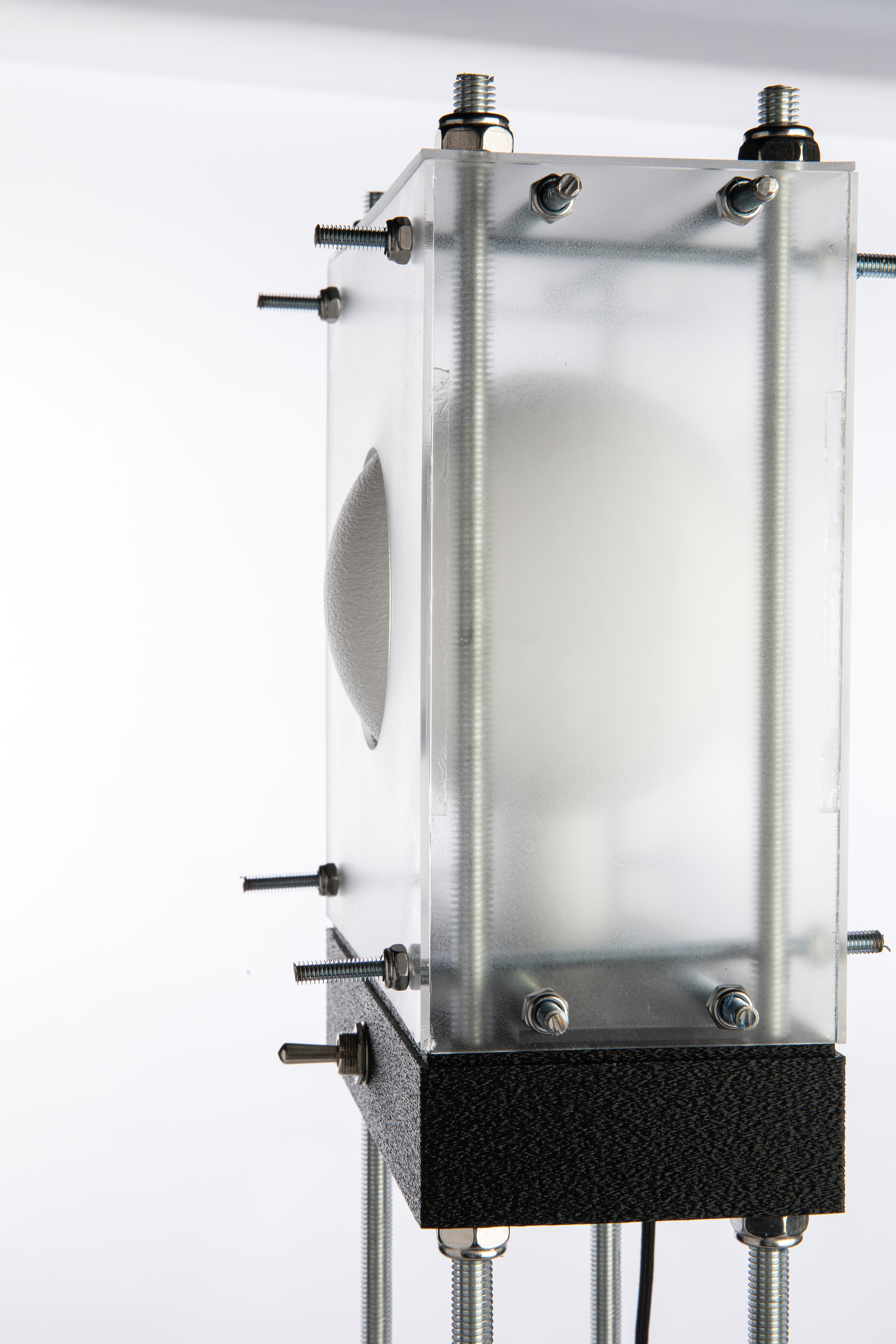
Fabrication & Assembly
Fabrication brought the digital design into physical form through three parallel processes: laser cutting the acrylic panels, 3D printing the structural and decorative components, and assembling the electronics inside the enclosure.
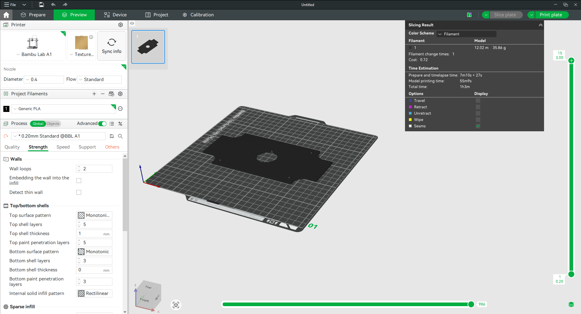
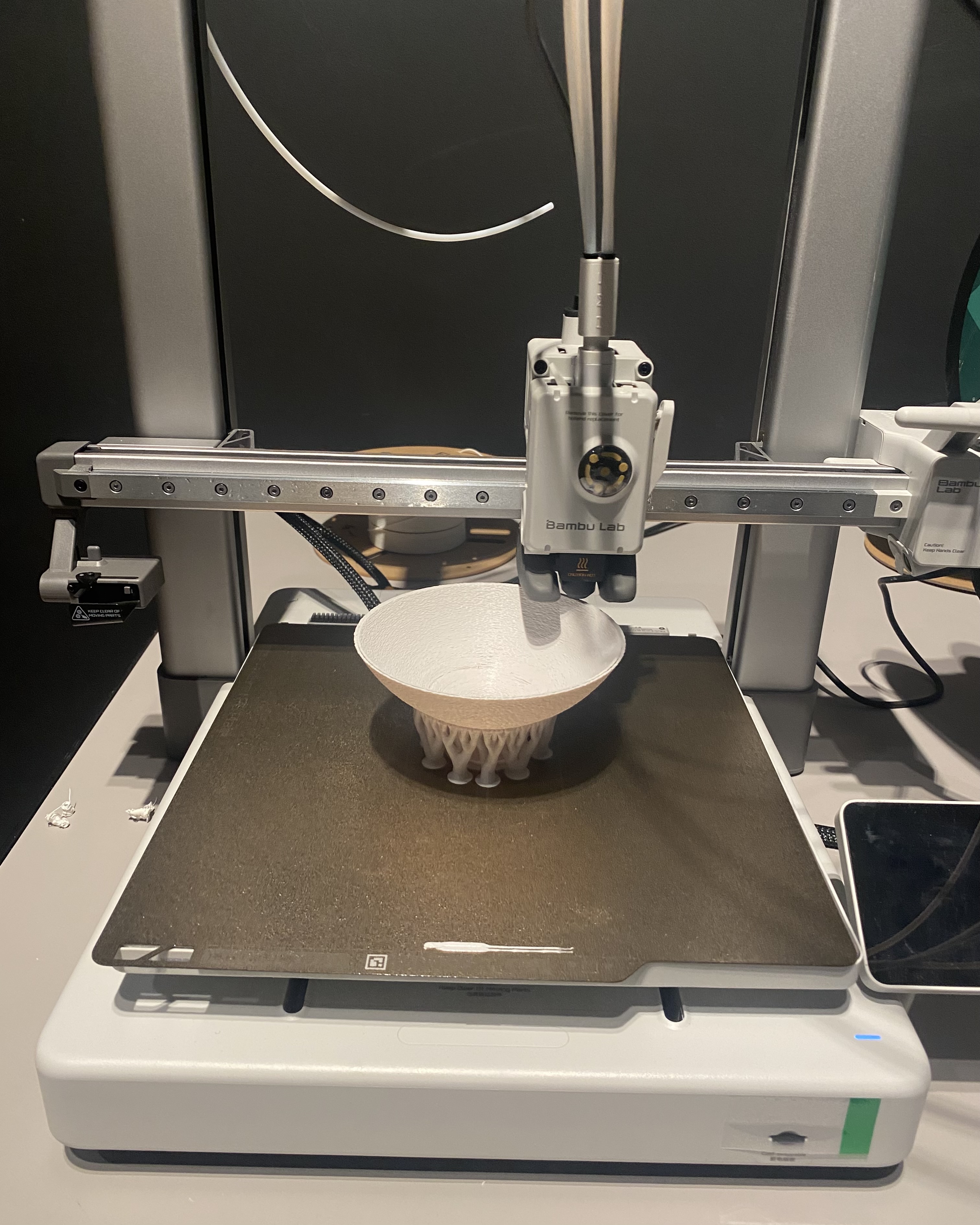
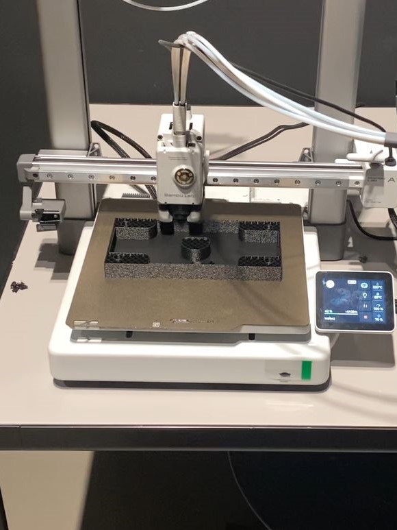
3D Printing
Printed on a Bambu Lab A1 printer. Regular PLA was used for the wiring enclosure, spherical diffuser, and frame mount. TPU was used for the leg protectors to allow flexibility and improve stability on a bedside surface.
Laser Cutting
Assembly
The Light Alarm was assembled with the rod-and-nut frame. The PCB was soldered, the LED strip connected via screw terminals, and the toggle switch mounted on the enclosure wall. The whole assembly was then tested for mechanical stability and electrical connectivity before final sealing.
Final Outcome
.jpg)
System Integration & Fabrication Methods
Mr. Lamperto integrates skills from across the Fab Academy curriculum into a single working system:
2D & 3D Design
Fusion 360 3D model of full assembly; AutoCAD 2D panel drawings for laser cutting; hand sketches to digital refinement.
Additive Fabrication
3D-printed wiring enclosure, spherical diffuser, leg protectors, and frame mount using PLA and TPU on Bambu Lab A1.
Subtractive Fabrication
Laser-cut 2 mm acrylic panels for the box enclosure; CNC-milled single-layer PCB on Roland DGshape machine.
Electronics Design & Production
Custom PCB designed in KiCad (schematic + layout), milled at the lab, soldered by hand, and tested with continuity checks.
Embedded Programming
Arduino firmware on XIAO ESP32-C3; controls WS2812B LEDs via addressable strip library; reads Blynk virtual pins for schedule and brightness data.
Wireless & App Integration
ESP32-C3 connects to Wi-Fi and syncs with Blynk IoT platform; custom dashboard built in Blynk for scheduling and manual control.
Testing & Evaluation
The system was tested in stages and as an integrated whole:
PCB continuity check: After milling and soldering, each trace was checked with a multimeter to confirm there were no shorts or open circuits before powering the board.
Firmware unit tests: Each mode (Scheduled and Manual) was tested independently by simulating toggle events and confirming LED response matched expected behavior (smooth fade vs. instant-on).
System integration test: The full assembly was tested with the app connected over Wi-Fi. Sleep and wake times were set in Blynk and the lamp was observed through a simulated sleep-wake cycle to confirm the transition animation ran correctly at the right times.
Mechanical test: The assembled enclosure was checked for structural rigidity, heat buildup from the LED strip, and stability on a flat surface with the TPU leg protectors.
Bill of Materials
All components were sourced locally in Saudi Arabia (Alrish.sa) or via Amazon.sa. Total project cost: $65.00 USD.
| Item | Description | Qty | Unit Price | Source |
|---|---|---|---|---|
| Acrylic enclosure | 2 mm acrylic sheet for laser-cut panels | 1 | $5.00 | alrish.sa |
| Locking nuts | (16) 6 mm nuts + (8) 10 mm nuts for rod frame | 1 pack | $3.00 | Amazon.sa |
| Threaded rods | 6 mm & 10 mm diameter steel rods | 1 set | $10.00 | Local hardware |
| PLA filament | White & black PLA for enclosure, diffuser, frame mount | 2 spools | $15.00 | Amazon.sa |
| TPU filament | Black TPU for flexible leg protectors | 1 spool | $1.00 | Amazon.sa |
| Toggle switch | Heavy-duty electrical toggle switch (mode selector) | 1 | $1.80 | Amazon.sa |
| Type-C cable | USB-C power cable for the ESP32 microcontroller | 1 | $9.30 | Amazon.sa |
| Screw terminals | 2-pin screw terminals (LED strip & toggle switch connections) | 2 | $0.50 | Amazon.sa |
| XIAO ESP32-C3 | Seeed Studio XIAO ESP32-C3 — Wi-Fi microcontroller | 1 | $14.00 | Amazon.sa |
| WS2812B LED strip | Addressable RGB LED strip — main light output | 1 | $5.00 | Amazon.sa |
| SMD resistor | 330 Ω — LED data signal protection | 1 | $0.20 | Amazon.sa |
| SMD capacitor | 1000 µF, 10 V electrolytic — power rail decoupling | 1 | $0.20 | Amazon.sa |
| Total Project Cost | $65.00 | |||
References & Sources
- [3] Seeed Studio. (2024). XIAO ESP32-C3 wiki and datasheet. wiki.seeedstudio.com
- [4] Blynk Inc. (2024). Blynk IoT documentation. docs.blynk.io
- [5] Adafruit Industries. (2024). NeoPixel / WS2812B library for Arduino. learn.adafruit.com
- [6] KiCad EDA. (2024). KiCad schematic and PCB design documentation. kicad.org
- [7] Autodesk. (2024). Fusion 360 user documentation. help.autodesk.com
- [8] Philips. (2024). SmartSleep Wake-up Light HF3520. philips.com — referenced as prior commercial art.
Reflection
Looking back on the full build process, this project challenged me across every discipline covered in Fab Academy — and pushed me to make decisions under real constraints of time, tools, and materials.
✅ What Worked Well
- The physical toggle switch proved to be an intuitive mode selector — more natural to use at night than opening an app
- The WS2812B LED strip produced smooth, convincing sunset and sunrise transitions when the fade algorithm was tuned correctly
- Blynk made it straightforward to build a functional IoT dashboard without writing server-side code
- TPU leg protectors gave the lamp a stable, non-slip base — a small detail that made a real difference in feel
- The rod-and-nut enclosure system worked as designed and made the lamp easy to open for iteration
⚠️ Challenges Encountered
- PCB milling required several iterations to tune the Roland machine depth settings — shallow cuts left copper bridges, deep cuts cut through the substrate
- Case-sensitive filenames on the Fab Academy server caused broken images that worked fine on Windows during development
- Synchronizing real-time clock on the ESP32 with Blynk scheduling needed careful NTP setup to avoid drift
- The spherical diffuser required two print iterations to achieve even light distribution without visible hot spots
- Blynk's free tier limits the number of active virtual pins, which constrained some planned features
💡 Lessons Learned
- Test every fabrication process at the smallest scale before committing — kerf testing for the laser cutter and depth testing for the CNC mill saved significant material
- Physical interaction (a toggle switch) makes a smart device feel more intentional and grounded than a phone-only interface
- Firmware debugging is much faster on a breadboard before the PCB is milled — never skip that step
- Document as you go — retro-documenting assembly steps from memory is harder and less accurate than photographing each step live
- Designing for disassembly (threaded rods) was the right call — I opened and modified the enclosure at least four times during integration
🚀 Future Opportunities
- Add a light sensor to create a fully closed-loop system that adapts the brightness to ambient room light conditions
- Integrate a sound module for optional white noise or nature sounds during the wind-down phase
- Replace Blynk with a local MQTT broker (e.g., Home Assistant) for full offline operation and privacy
- Develop a companion iOS/Android app with richer schedule control and sleep quality tracking
- Explore warm-white and cool-white LED combinations for more accurate color temperature shifting rather than RGB alone
- Miniaturize the PCB to reduce enclosure size and produce a more product-like form factor
📁 Project Files
All project documents including CAD files, PCB designs, firmware, and fabrication files are available to download below.
⬇ Download Project Documents (4.4 MB)Full project files on GitLab
Source code, KiCad PCB files, Fusion 360 models, and all documentation