Assignment Brief
👥 Group Assignment
- Design a machine that includes mechanism + actuation + automation + application
- Build the mechanical parts and operate it manually (Part 1)
- Actuate and automate the machine (Part 2)
- Document the group project
👤 Individual Assignment
- Document your individual contribution to the group machine
- My role: Extruder Mount Design & 3D Printing
Clay 3D Printer → CNC Plotter
The Vujade Node team set out to build a clay extrusion 3D printer — adapting an existing closed-source FDM printer to push clay through a custom extruder mount using a belt-driven syringe plunger. After iterating through the belt mechanism and a lead screw redesign, and identifying a motor driver bottleneck, the team pivoted the machine into a fully operational 2-axis CNC pen plotter, completing it within the week's time constraint.
Machine Summary
Type: 2-axis CNC pen plotter (evolved from clay extruder) · Controller: RAMPS 1.4 + MEGA · Firmware: Marlin · Extruder: NEMA 17 stepper + belt-driven syringe plunger · Driver: A4988 / DRV8825 · Max travel: 150 mm
Team Roles
Development Phases
Belt Mechanism
NEMA 17 stepper with pulley and belt translating rotation into linear plunger compression. MVP for rapid testing.
Lead Screw + Nozzle Mount
Belt skipped steps under syringe weight — replaced with lead screw for better torque. Custom nozzle mount designed and printed.
RAMPS 1.4 + Marlin
Configured Marlin firmware via Pronterface. A4988 motor driver identified as insufficient for clay extrusion torque.
CNC Plotter
Pivoted to 2-axis pen plotter. Fully operational, producing clean output within the week's constraint.
Extruder Nozzle Mount — Design & Fabrication
My role in the machine week was the design and 3D printing of a custom extruder nozzle mount to replace the original FDM print head on the closed-source printer. The objective was to adapt the printer for clay extrusion by creating a mount that could securely hold a clay nozzle system while maintaining alignment, rigidity, and compatibility with the existing X-axis carriage.
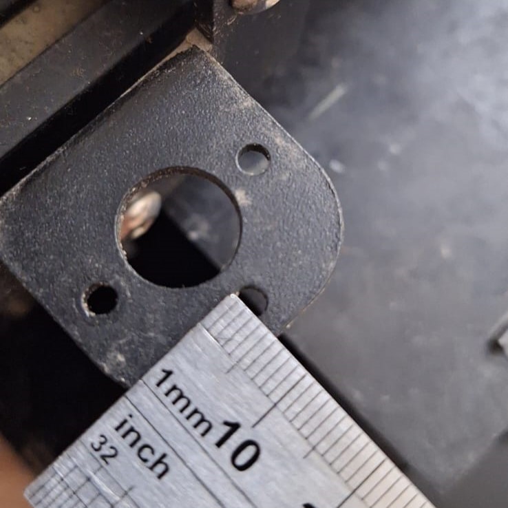
Step 1 — Analysing the Original Print Head
The process began by carefully measuring the original FDM print head assembly — its mounting interface, screw hole locations, spatial clearances, and the carriage interface geometry. Every dimension mattered: the new mount had to fit the existing X-axis carriage exactly, or the nozzle would not align with the build plate.
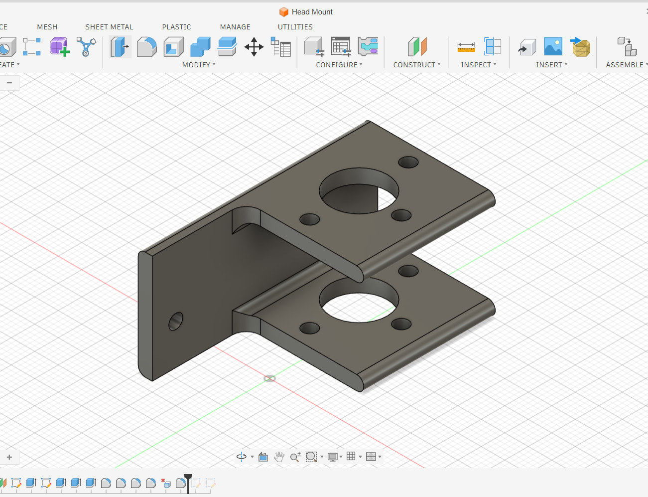
Step 2 — Designing the Mount in Fusion 360
Based on the measurements, I designed the custom mount in Fusion 360. The design had to balance several constraints:
- Structural integrity — the mount must support the syringe tube and withstand the lateral forces during movement without flexing
- Nozzle alignment — the clay nozzle must sit perpendicular to the build plate, centred on the X/Y axes
- Clay flow clearance — sufficient space around the extrusion point to avoid clogging
- Interface compatibility — screw hole positions and carriage geometry matched exactly to the original head
- Ease of installation — the mount must be removable and reinstallable without tools to allow iteration
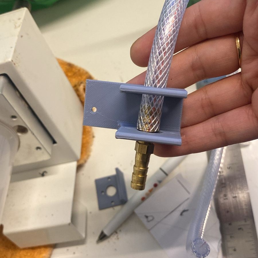
Step 3 — 3D Printing & Assembly
The mount was printed in PLA with printing parameters optimised for durability in load-bearing regions (higher infill, thicker perimeters). After fabrication, I assembled the mount onto the printer's X-axis carriage, replacing the original print head, then attached the clay nozzle system.
Alignment tests were performed to verify the nozzle was perpendicular to the build plate and correctly positioned along all three axes. Iterative adjustments were made to eliminate vibration and ensure stable, consistent extrusion.
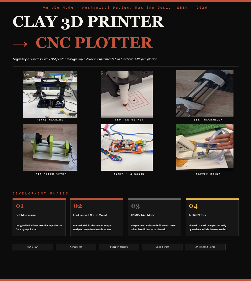
Group Poster Design
As part of the project requirements, we were asked to produce a one-minute video and a poster. I designed the group project poster, condensing the team's work into a single visual layout that communicates the machine concept, development stages, hardware stack, and final outcome. The project video was created by my colleague Sarah and can be viewed on the group assignment page.
RAMPS 1.4 & Marlin Calibration
While I handled the mechanical mount, Sarah configured the electronics and firmware. The extruder motor was connected to the E0 port on the RAMPS 1.4 shield using an A4988 stepper driver, and Marlin G-code was used via Pronterface for calibration and testing.
| Command | Purpose | Result |
|---|---|---|
| M302 S0 | Allow Cold Extrusion | Bypasses the heater/nozzle safety check — not needed for clay |
| M92 E1.0 | Steps per mm | Configured 1:1 ratio (1 unit = 1 mm of plunger travel) |
| G1 E50 F60 | 50 mm move test | Verified plunger moved exactly 5 cm as expected |
| M211 S1 | Software endstops | Enabled to prevent over-travel beyond the 150 mm syringe limit |
What I Learned
Machine week was the most collaborative assignment in Fab Academy — every design decision affected someone else's work. My task was the nozzle mount, but its dimensions had to match Sarah's extruder. Getting something physically fabricated to work inside a system designed by two people simultaneously requires a level of precision and communication that solo assignments don't demand.
Designing the mount in Fusion 360 reinforced how much mechanical design is really about constraints. The creative work isn't choosing the shape — it's satisfying all the constraints at once. Each constraint narrows the design space, and the final shape emerges from what's left.
The belt-skipping problem — where adding the syringe caused the belt to lose steps — was the most instructive failure of the week. It wasn't obvious until the full assembly was in place, which is exactly why building and testing matters more than predicting. The pivot to a lead screw (and eventually to the CNC plotter) showed how a team can reframe a constraint as a design decision rather than a failure. The plotter works beautifully. That's a success.