Assignment Tasks
🔬 Group Assignment
- Complete lab safety training
- Test runout, alignment, fixturing, speeds, feeds, materials, and toolpaths for the machine
👤 Individual Assignment
- Design, mill, and assemble something big (~meter-scale)
Extra Credit
- ⭐ No fasteners or glue
- ⭐ Include curved surfaces
- ⭐ Use three-axis toolpaths
Key Concepts
What is CNC Milling?
CNC (Computer Numerical Control) milling is a subtractive manufacturing process where a rotating cutting tool removes material from a workpiece following a precisely programmed path. Unlike laser cutting, which burns through material in two dimensions, CNC milling can work across multiple axes — making it suitable for cutting large, structural parts from sheet materials like plywood, as well as three-dimensional surface carving.
What are CNC Bits (End Mills)?
CNC bits, also called end mills, are the rotating cutting tools mounted to the CNC spindle. They come in different diameters, flute counts, and geometries — each suited to different materials and cutting strategies. For this assignment, a 6mm downcut 2-flute end mill was used. Downcut bits push chips downward, which helps produce cleaner top surfaces on plywood and reduces tearout — an important consideration for visible joinery.
Step-by-Step Documentation
Design in Fusion 360
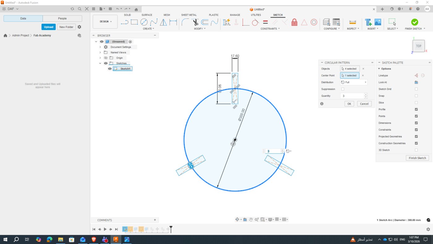
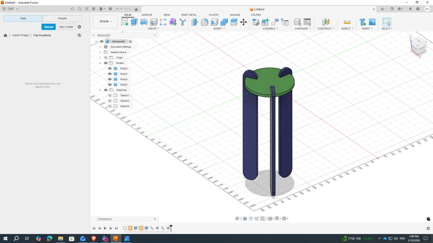
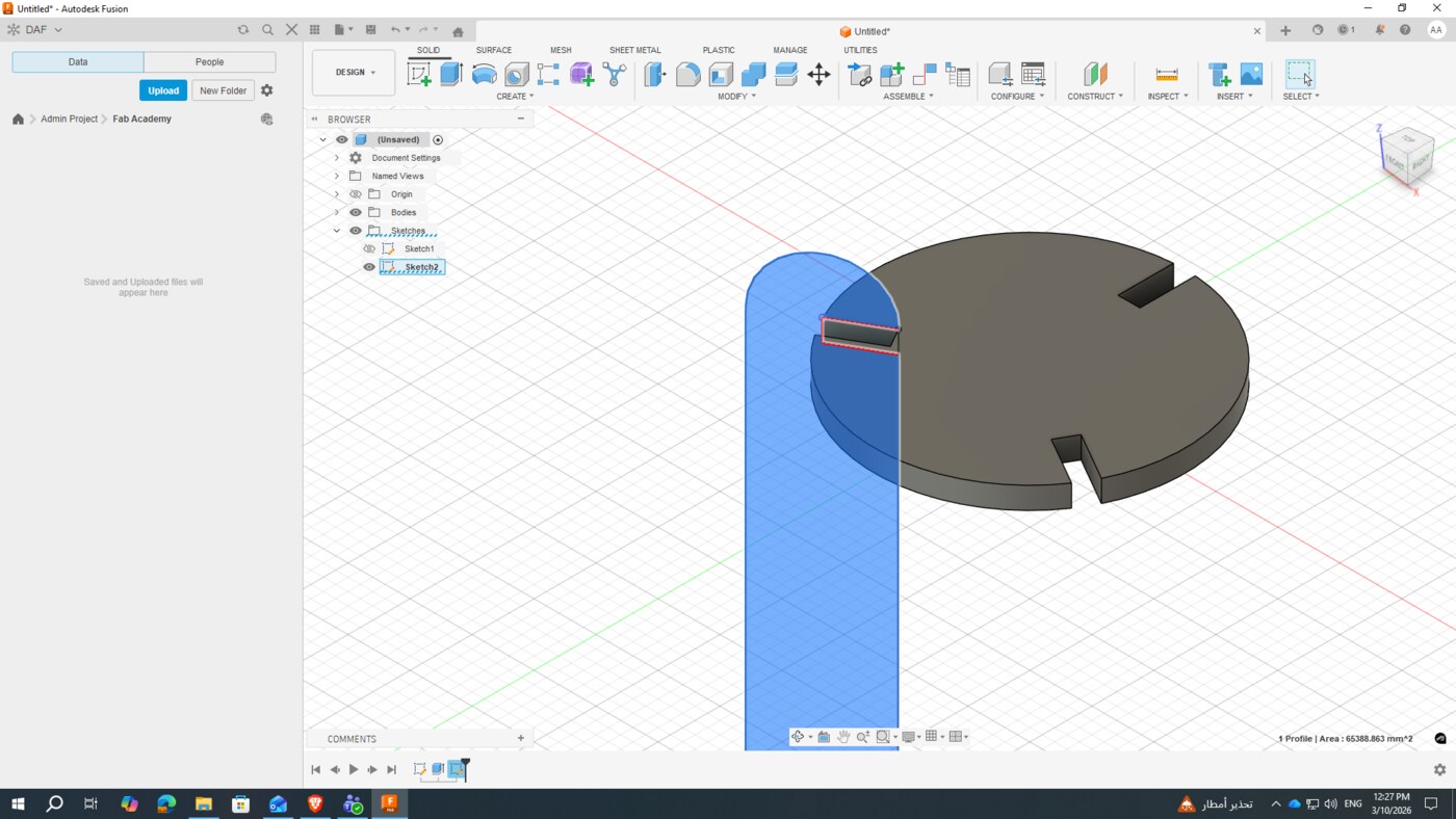
For this assignment, I chose to design and build a press-fit stool — a piece of functional furniture that holds together entirely through interlocking joints, with no screws, nails, or glue required. The design was driven by the material thickness of the plywood I planned to use.
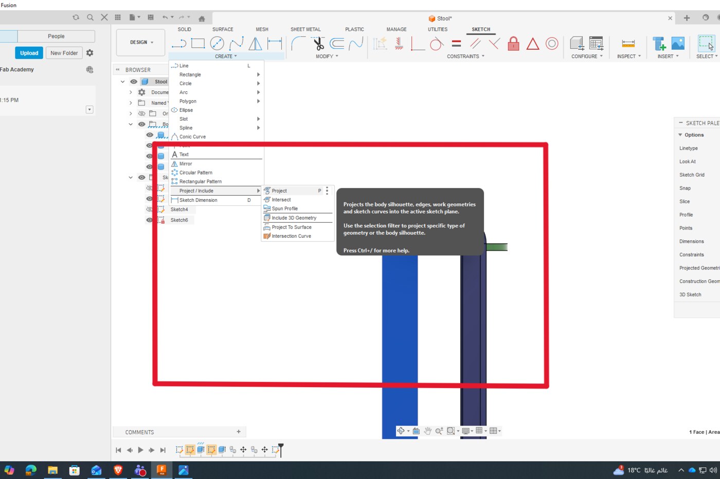
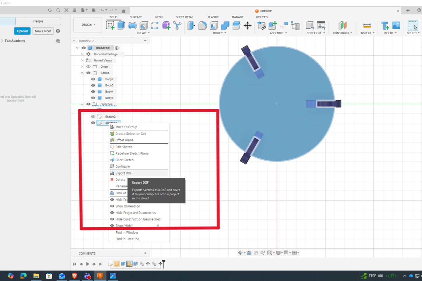
I used Fusion 360 to model the stool parametrically, defining the material thickness and joint tolerances as adjustable parameters from the start. This made it straightforward to refine the design as I learned more about the machine's actual kerf. Once the design was complete, I exported each component as a DXF file for import into the CAM software.
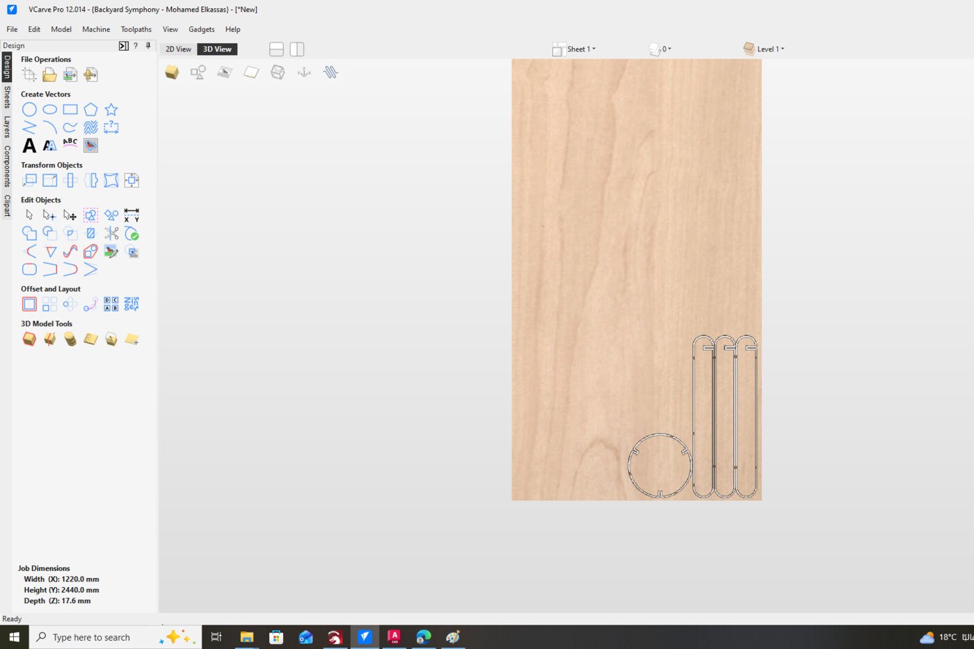
CAM Setup in VCarve
With the DXF files ready, I imported them into VCarve to set up the toolpaths for the CNC machine. CAM (Computer-Aided Manufacturing) software translates the 2D design vectors into machine instructions — defining how the bit should move, at what depth, and in what sequence.
Board & Tool Setup
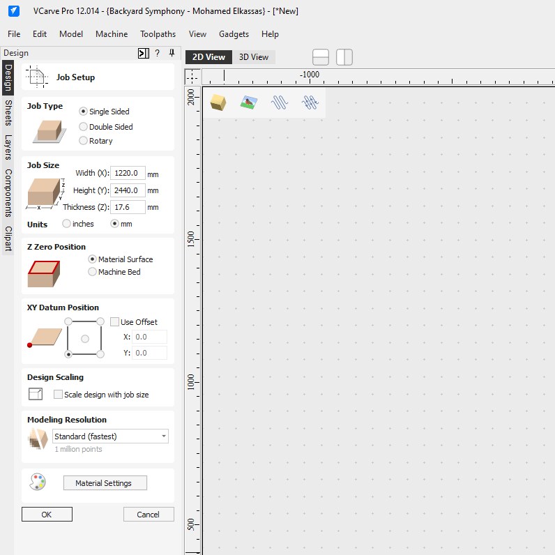
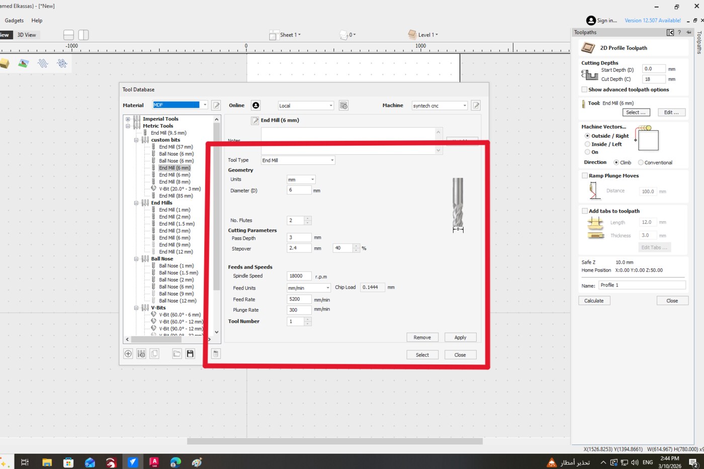
I configured the workpiece dimensions to match the full plywood sheet, then selected the cutting tool based on material and joint requirements.
| Parameter | Value | Notes |
|---|---|---|
| Tool Geometry | ||
| Tool Type | End Mill | Downcut, 2-flute |
| Tool Diameter | 6 mm | Defines minimum slot width and dogbone radius |
| No. of Flutes | 2 | |
| Cutting Parameters | ||
| Pass Depth | 3 mm | Material removed per pass |
| Number of Passes | 2 | |
| Total Cut Depth | 18 mm | Through full plywood thickness |
| Stepover | 2.4 mm (40%) | |
| Feeds & Speeds | ||
| Spindle Speed | 18,000 RPM | |
| Feed Rate | 5,200 mm/min | Horizontal cutting speed |
| Plunge Rate | 300 mm/min | Vertical entry speed |
| Chip Load | 0.1444 mm | Auto-calculated |
| Toolpath Settings | ||
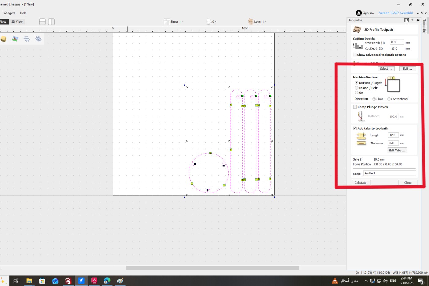
| Machine Vectors | Outside / Right | Climb direction |
| Tab Length | 12 mm | Bridges that hold parts in place |
| Tab Thickness | 3 mm | |
| Safe Z | 10 mm | Clearance height between moves |
Dogbone Fillets
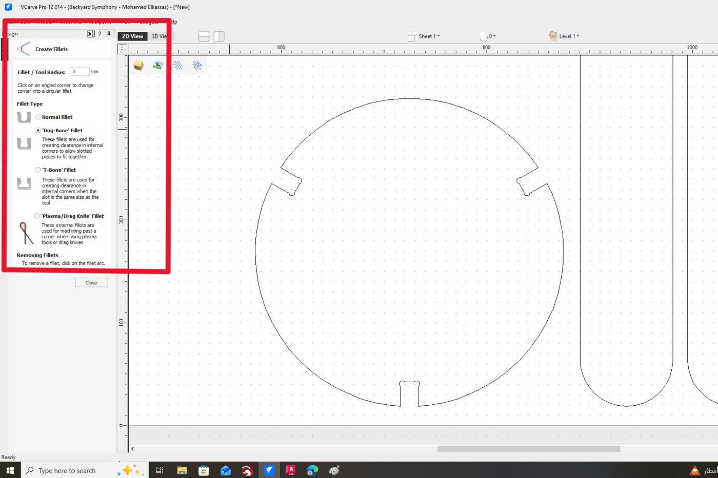
Because CNC bits are circular, they cannot cut perfectly sharp internal corners — they always leave a small radius. To allow rectangular press-fit joints to seat fully flush, I added dogbone fillets to all internal corners using VCarve's automatic fillet tool. This small circular cutout at each corner gives the mating piece enough clearance to fit completely.
Toolpaths & Tabs
I selected the outer outlines and set them as outside profile toolpaths, instructing the CNC to cut along the outside of each vector. I also added tabs — small bridges of uncut material — to hold the pieces in place during milling and prevent them from shifting or being thrown by the spinning bit.
Fabrication & Assembly
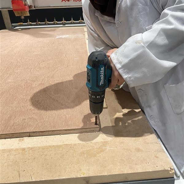
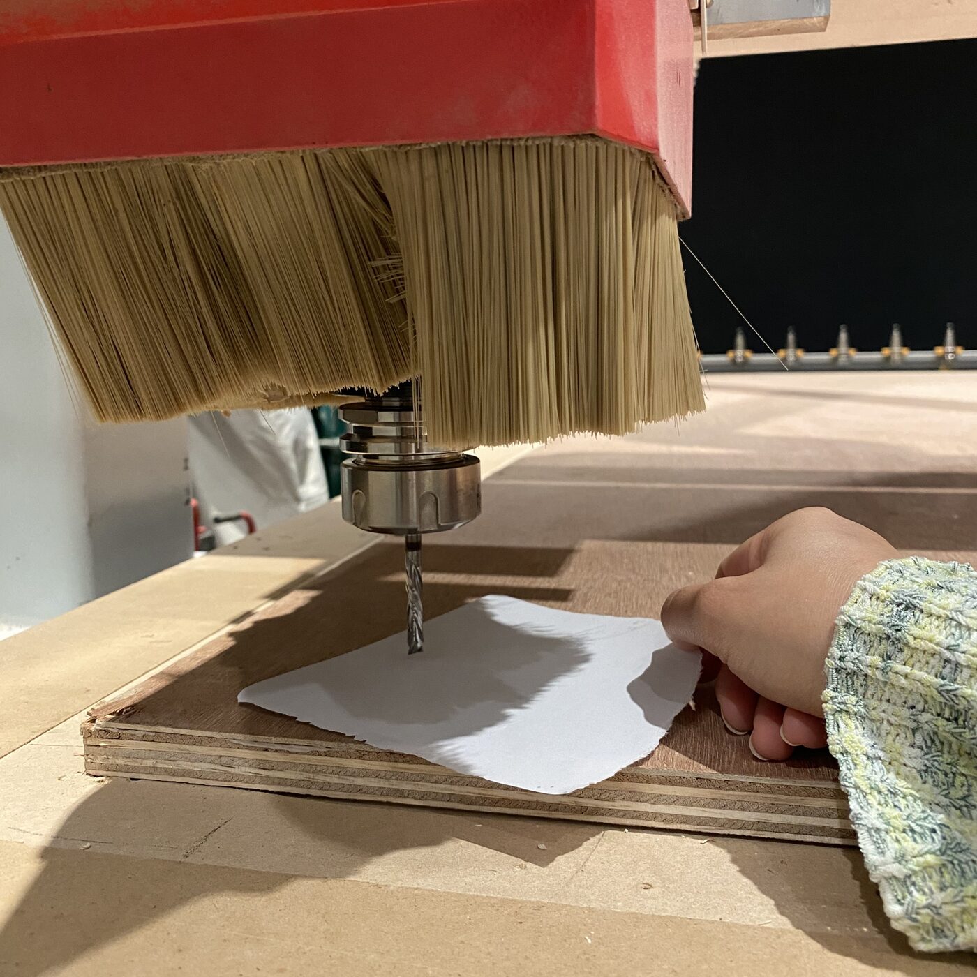
Machine Setup
Before starting the job, I secured the plywood sheet to the CNC bed using screws at the corners, making sure all fixings were well outside the cutting area to avoid tool collision. I then set the Z-axis origin, positioning the bit precisely at the top surface of the material.
Running the Job
I remained beside the machine throughout the entire operation with the emergency stop within reach, and wore both ear and eye protection. The machine ran smoothly, following the programmed toolpaths without issue.
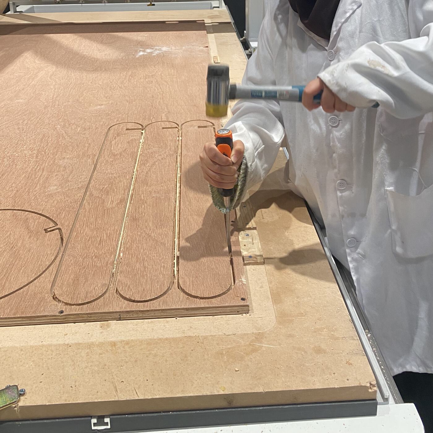
Post-Processing
Once milling was complete, I used a chisel to carefully break the tabs, freeing each piece from the sheet. I then lightly sanded the edges to remove any burrs left by the cutting process.
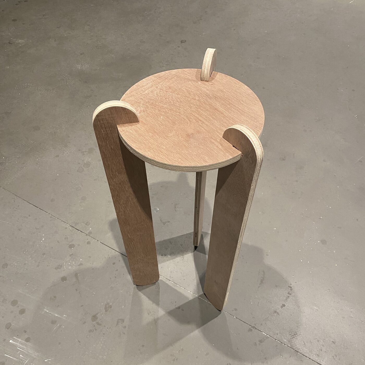
Assembly
With all parts cleaned up, I assembled the stool by hand. The press-fit joints were precise enough that no rubber mallet was needed — every piece slotted together smoothly and the final structure was rigid and stable, held together entirely by friction.
Download the Fusion 360 source file to explore or modify the parametric stool design.
Reflection
This week was the most physically tangible assignment so far — going from a digital model to a piece of furniture I could actually sit on was genuinely satisfying. The scale of the project made every decision feel consequential: a small error in the joint dimensions or tool settings could have meant poorly fitting parts or wasted material.
Learning to work with VCarve and understanding CAM concepts like outside vs. inside toolpaths, tab placement, and dogbone fillets added an important layer of knowledge between design and fabrication. These aren't just software steps — they reflect real physical realities of how round tools interact with square geometry.
The fact that the stool came together by hand with no fasteners or adhesive was the most rewarding outcome. It confirmed that getting the parametric design and kerf compensation right from the start makes everything else fall into place — literally.