Overview
👥 Group Assignment
- Demonstrate and compare toolchains and development workflows for available embedded architectures
- Document work to the group page and reflect individually
🧑💻 Individual Assignment
- Browse through the datasheet for a microcontroller
- Write and test a program for an embedded system to interact with local input/output devices and communicate with remote connections
Group Assignment
Toolchain Comparison — ESP32-S3 vs RP2040
For the group assignment, our lab compared the toolchains and development workflows of two microcontroller architectures. I tested the ESP32-S3 while my partner worked on the RP2040 (Raspberry Pi Pico). Both boards were configured in the Arduino IDE and tested with basic programs to understand the differences in compilation, uploading, and debugging.
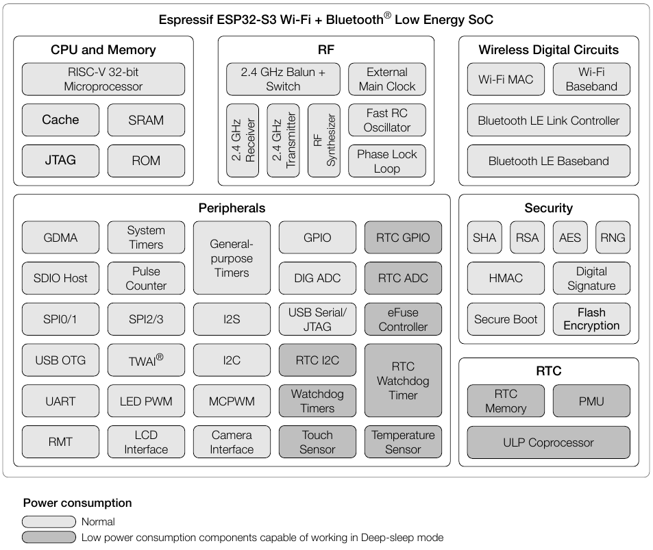
ESP32-S3 Functional Block Diagram
The functional block diagram from the ESP32-S3 datasheet shows how all internal components are organized and connected. The chip is divided into four main areas:
- CPU and Memory — a RISC-V 32-bit microprocessor with Cache, SRAM, ROM, and JTAG support for debugging.
- RF — the 2.4 GHz radio section including a Balun + Switch, receiver, transmitter, RF synthesizer, and a Phase Lock Loop for stable frequency generation.
- Wireless Digital Circuits — dedicated hardware blocks for Wi-Fi (MAC + Baseband) and Bluetooth LE (Link Controller + Baseband), handled independently from the CPU.
- Peripherals — a rich set of interfaces including GPIO, ADC, SPI, I²C, UART, USB OTG, I²S, Touch Sensor, Camera Interface, LED PWM, and more. Components shaded in dark grey can operate in Deep-sleep mode with very low power consumption.
- Security — hardware-accelerated encryption (AES, SHA, RSA), Secure Boot, Flash Encryption, and a True Random Number Generator (RNG).
- RTC — a real-time clock domain with its own memory, Power Management Unit (PMU), and ULP (Ultra Low Power) coprocessor that can run tasks while the main CPU sleeps.
What is a Toolchain?
An embedded system toolchain is a set of software tools — compiler, assembler, linker, and debugger — that converts source code into machine code for a specific target processor. The toolchain follows a sequence: Compiler → Assembler → Linker → Flash to device.
The documentation on the RP2040 (Raspberry Pi Pico), including the architecture breakdown, toolchain comparison, and IDE setup for both boards, is available on my colleague's page:
Individual Work
Part 1 — Reading the Datasheet (XIAO ESP32-S3)
For this assignment I worked with the Seeed Studio XIAO ESP32-S3, since my final project requires Wi-Fi connectivity and addressable LED control. Before writing any code, I read through the datasheet to understand the hardware constraints and capabilities of the board.
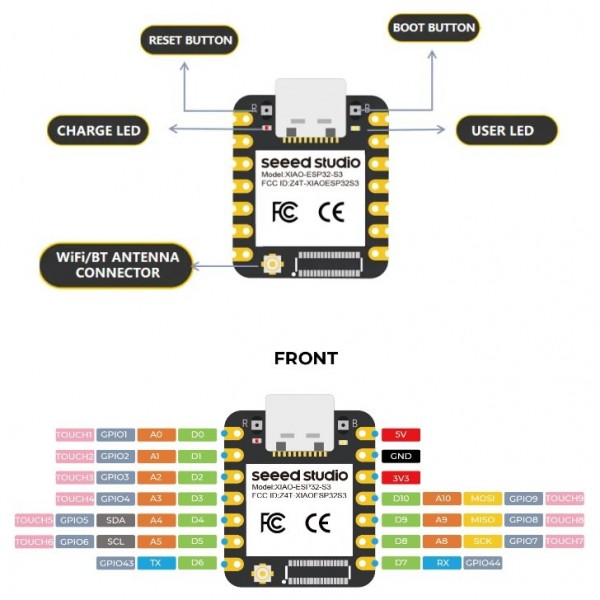
Pinout
The pinout diagrams show every GPIO pin, its primary function, and which peripherals it can be mapped to through the GPIO Matrix. Understanding this was essential before designing any circuit.
Key Findings from the Datasheet
- Processor: Xtensa dual-core 32-bit LX7 up to 240 MHz, with FPU and 128-bit data bus.
- Memory: 512 KB SRAM, 384 KB ROM, plus 16 KB RTC SRAM that persists in Deep-sleep.
- GPIO: 13 user-accessible pins (D0–D12) on the XIAO module. GPIO 0 is the Boot button — a strapping pin that configures startup mode and should not be driven externally.
- Wireless: 802.11 b/g/n Wi-Fi (up to 150 Mbps) and Bluetooth 5 LE (up to 2 Mbps), sharing one antenna.
- ADC: 9 analog-capable pins on the XIAO (D0–D5, D8–D10). ADC2 pins cannot be used while Wi-Fi is active.
Part 2 — Programming the Board (Arduino Blink Test)
After reading the datasheet, I moved on to physically programming the XIAO ESP32-S3. I used the Arduino Blink example to light a through-hole LED connected to D1 (GPIO 2) through a 200 Ω resistor, testing that the board could upload and run code correctly.
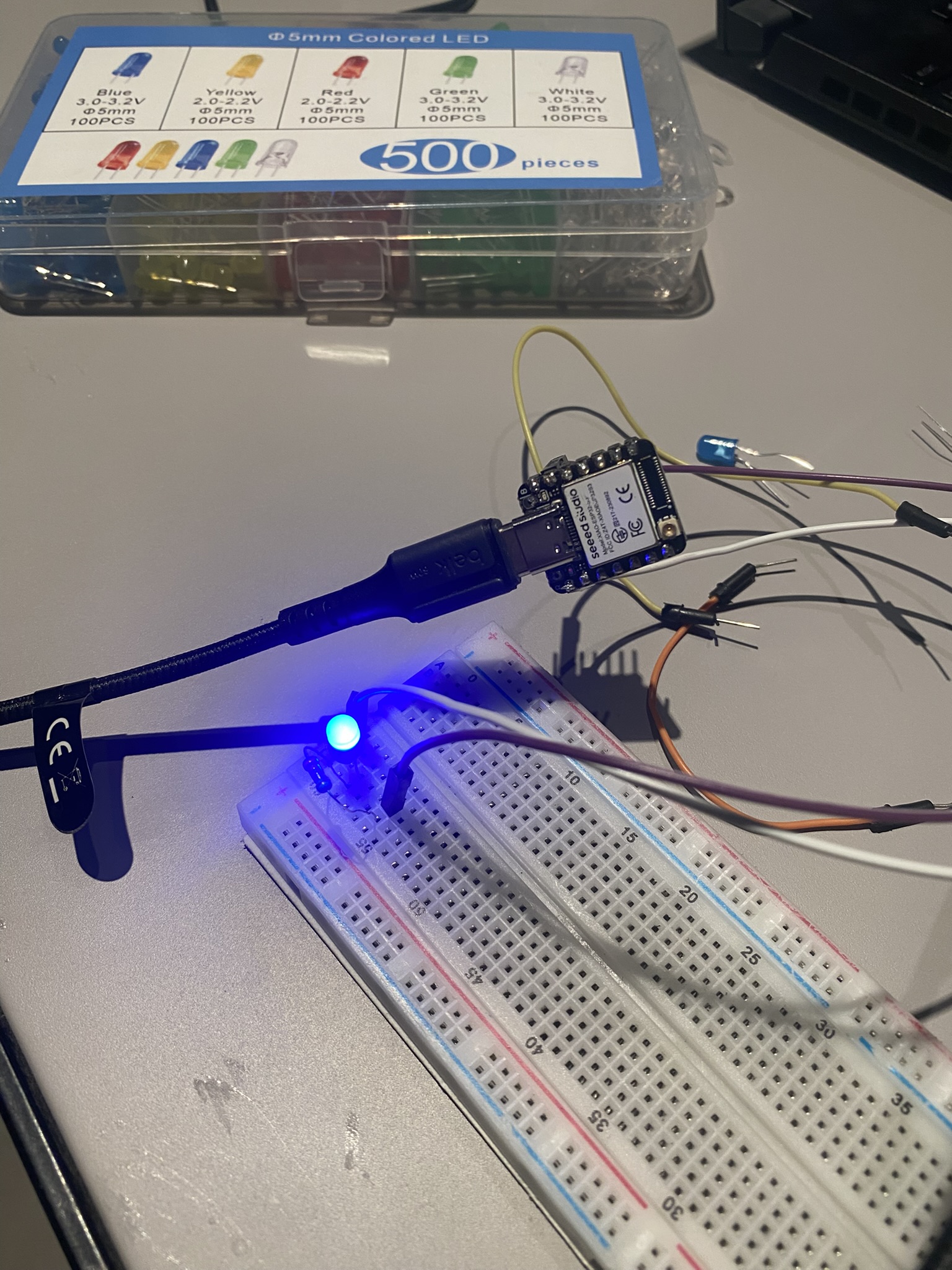
Circuit Setup
I wired the LED on a breadboard with a 200 Ω current-limiting resistor connected between D1 and the LED anode, with the cathode to GND.
Arduino IDE Setup
To program the XIAO ESP32-S3 in Arduino IDE, I installed the Seeed board support package:
- Open Arduino IDE → File → Preferences
- In Additional Boards Manager URLs, add:
https://files.seeedstudio.com/arduino/package_seeeduino_boards_index.json - Go to Tools → Board → Boards Manager, search for Seeed XIAO ESP32S3 and install it
- Select Tools → Board → XIAO_ESP32S3
- Connect the board via USB-C and select the correct port under Tools → Port
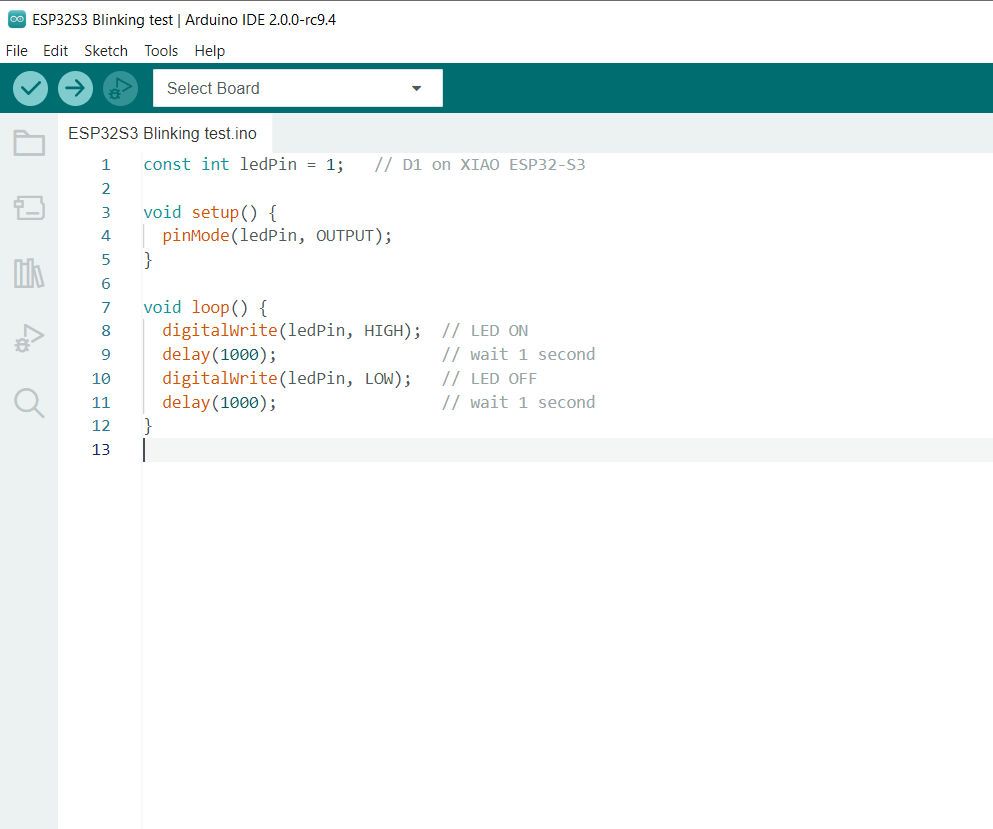
The Code
I used the standard Blink example, modified to target D1 (GPIO 2) which maps to pin 2 on the XIAO ESP32-S3
const int ledPin = 2;   // D1 (GPIO2) on XIAO ESP32-S3

void setup() {
  pinMode(ledPin, OUTPUT);
}

void loop() {
  digitalWrite(ledPin, HIGH);  // LED ON
  delay(1000);                 // wait 1 second
  digitalWrite(ledPin, LOW);   // LED OFF
  delay(1000);                 // wait 1 second
}
Result
After uploading, the LED blinked on and off every second as expected, confirming the board, toolchain, and wiring were all working correctly.
Testing & Debugging
Getting the LED to blink wasn't immediate — two separate issues came up during assembly and wiring, both of which required careful diagnosis to fix.
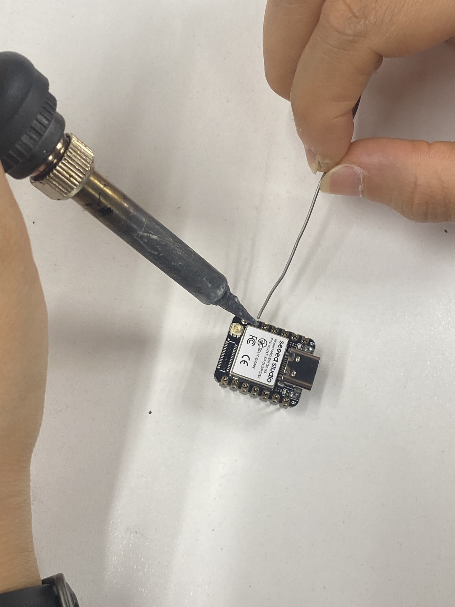
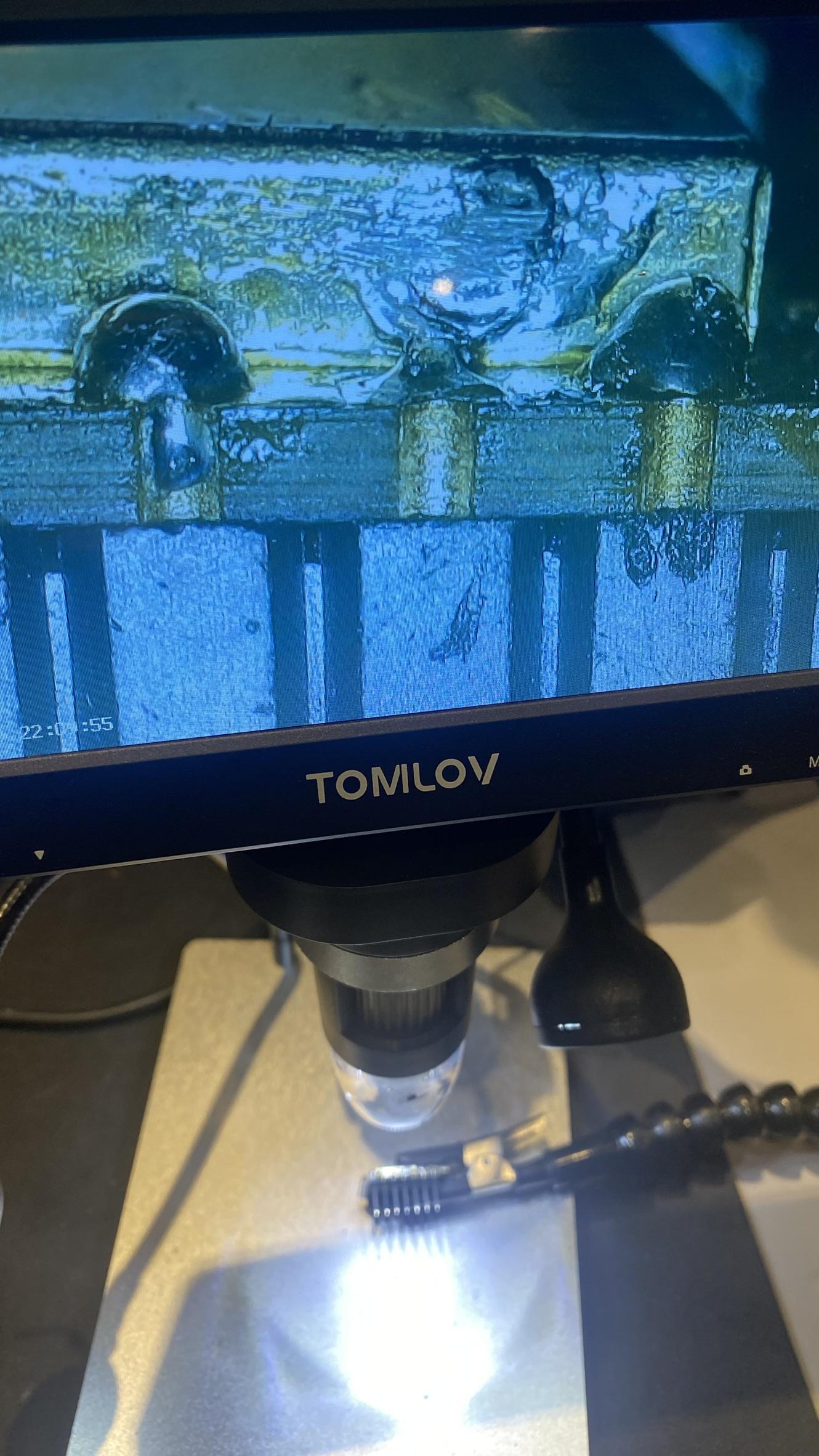
Issue 1 — Bridged Solder Joints on the Header Pins
When soldering the header pins onto the XIAO ESP32-S3, I accidentally bridged several adjacent pins with excess solder. The bridges created short circuits between GPIO pins, which would have caused unpredictable behavior or damaged the board if powered up that way.
I used a digital microscope (Tomilov) to magnify the solder joints and identify exactly which pins were bridged. Under magnification the cold joints and bridges were clearly visible — something impossible to see reliably with the naked eye at this pitch.
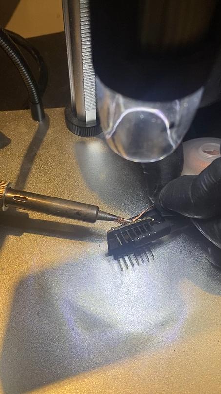
Fix
I cleaned each bridge using the soldering iron tip and solder wick to wick away the excess.
Issue 2 — Wrong GPIO Pin Wired (D0 instead of D1)
After uploading the Blink sketch, nothing happened. I had written the code correctly targeting D1 (GPIO 2), but the LED didn't respond. After double-checking the code and the upload (both were fine), I traced the wiring and found I had connected the LED to D0 (GPIO 1) instead of D1 (GPIO 2).
The confusion: The XIAO ESP32-S3 labels its pins as D0, D1, D2… but these do not map sequentially to GPIO 0, 1, 2. D0 is GPIO 1, and D1 is GPIO 2. Using the Arduino pin number 2 in code while wiring to the physical D0 header will always result in a mismatch.
Fix
Moved the LED wire from the D0 header to the D1 header. The LED blinked immediately on the next power cycle — no code change needed. The lesson: always cross-reference the silkscreen label with the pin table in the datasheet before wiring.
Reflection
Reading the datasheet before touching any hardware was genuinely useful. It revealed constraints I wouldn't have noticed until something broke — particularly the strapping pin restrictions and the current requirements during RF operation. These are the kinds of details that prevent design mistakes before they happen.
The blink test was simple but important. It confirmed the entire chain works: board selection in Arduino IDE, USB upload, and GPIO output. Having a verified working baseline means any future code failures can be traced to the logic, not the setup or environment.
Overall, this week reinforced that datasheets are not just reference documents — they are design tools. Checking electrical characteristics and pin functions before building a circuit helps identify potential problems early and avoids costly redesigns later.