Assignment Tasks
🔬 Group Assignment
- Test the design rules for the lab's 3D printer(s)
👤 Individual Assignment
- Design, document, and 3D print an object that could not be made subtractively
- 3D scan an object (and optionally print it)
What is 3D Printing?
Definition
3D printing is an additive manufacturing process that builds physical objects layer by layer from a digital design file. Unlike subtractive manufacturing — which removes material from a solid block — 3D printing only adds material where needed, making it ideal for complex geometries that traditional fabrication methods cannot achieve.
Types of 3D Printers
Different printing techniques offer different levels of detail, material compatibility, and surface finish. The three most common processes used in fabrication are:
FDM — Fused Deposition Modeling
Extrudes thermoplastic filament (such as PLA or ABS) through a heated nozzle, building the object layer by layer. FDM is the most widely used method for prototyping functional parts, enclosures, and artistic objects. It is cost-effective and accessible, though surface finish is more textured than other methods.
SLA — Stereolithography
Uses a UV laser to cure liquid resin layer by layer, producing parts with very high resolution and smooth surface finish. Ideal for detailed prototypes, jewelry, medical models, and anything requiring fine features. Materials range from rigid and flexible to castable and dental resins.
SLS — Selective Laser Sintering
Fuses powdered material (typically nylon) using a laser. Produces strong, functional parts without the need for support structures, since the surrounding powder supports the print. Best suited for complex geometries and end-use parts.
Choosing the Right Printer
The choice of printing method depends on the application — FDM is best for quick, affordable prototypes; SLA excels at precision and finish; SLS is preferred for functional, support-free complex parts. Material properties and post-processing requirements also influence the decision.
Key FDM Settings Explained
| Setting | What It Controls |
|---|---|
| Infill Density | The amount of internal material — 0% is hollow, 100% is fully solid. Affects strength, weight, and print time. |
| Wall Loops | The number of outer shell perimeters. More loops mean stronger, thicker walls and better surface quality. |
| Layer Height | Thinner layers produce smoother, more detailed prints but take longer. Thicker layers print faster with less detail. |
| Supports | Temporary structures printed beneath overhanging geometry to prevent collapse. Removed after printing. |
| Build Plate Adhesion | Skirt, brim, or raft options that help the first layer stick to the bed and prevent warping. |
Standard Production Workflow
Design or Download the Model
Create a 3D model using CAD software such as Fusion 360, Solidworks, or Rhino — or download open-source models from Thingiverse, GrabCAD, or Cults3D.
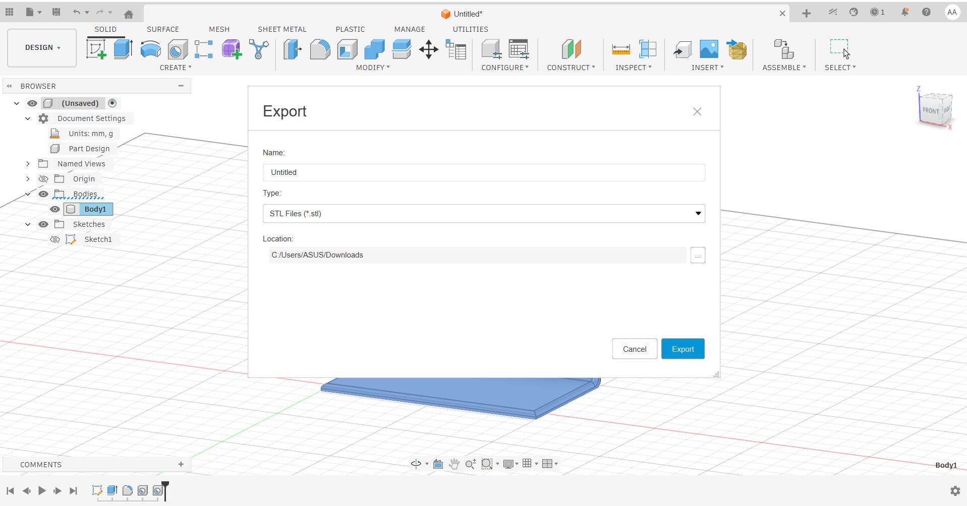
Export as STL
Save the model as an STL file — the standard input format accepted by virtually all slicing software and 3D printers.
Slice the File
Import the STL into a slicer such as Bambu Studio, Cura, or PreForm. Configure print settings and generate the G-code — the machine instructions that control movement, speed, and extrusion.
Send to Printer
Upload the G-code to the machine via USB, SD card, or wireless connection, then start the print.
Post-Processing
Remove the printed part from the bed, detach any support structures, and sand or clean surfaces as needed.
Design Rules Testing — Bambu Lab A1
I tested the design rules of the Bambu Lab A1 3D printer using two separate test files downloaded from Thingiverse. The goal was to understand the machine's actual capabilities — minimum feature sizes, overhang limits, bridge length, and dimensional accuracy — before committing to production prints.
Test 1 — Comprehensive Design Rules
| Feature | Result |
|---|---|
| M4 Nut fit test | ✓ Pass |
| Wave / rounded surfaces | ✓ Pass |
| Star / sharp edges | ✓ Pass |
| Holes: 3, 4, 5 mm | ✓ Pass |
| Minimum printable distance | ✓ 0.3 mm and above |
| Z height steps: 0.1–1.1 mm | ✓ All succeeded |
| Bridge print: 2, 4, 8, 16 mm | ✓ All succeeded |
| Sphere mix — 7 mm height | ✓ Pass |
| Pyramid — 7 mm height | ✓ Pass |
| Overhang: 25°–70° | ✓ All succeeded |
| Warping | ✓ No warping |
| 3D print font legibility | ✓ Pass |
| Surface flatness | ✓ Good |
| Spike — 21 mm from base | ✓ Pass |
| Hole in wall — 4 mm diameter | ✓ Pass |
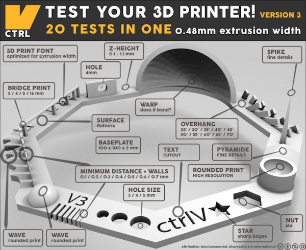
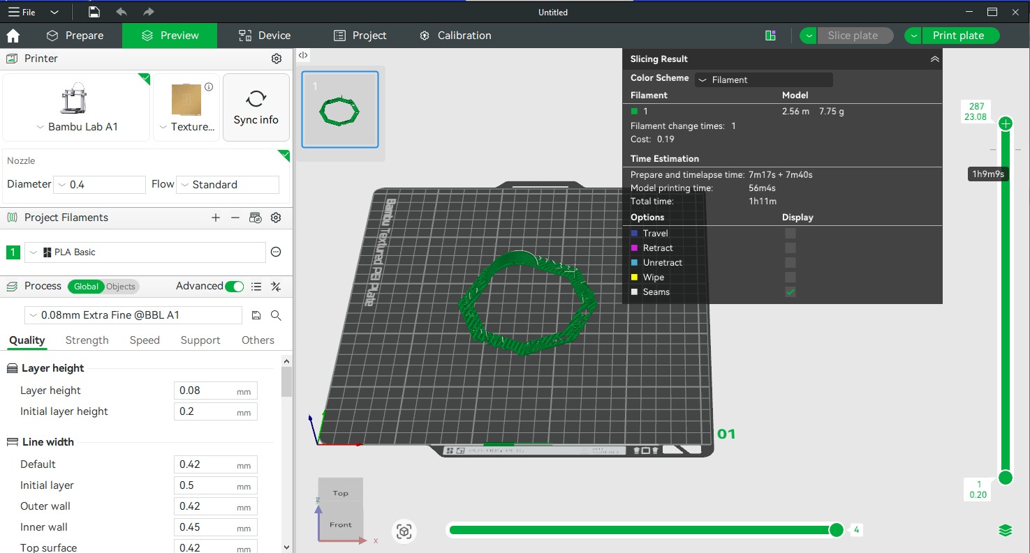
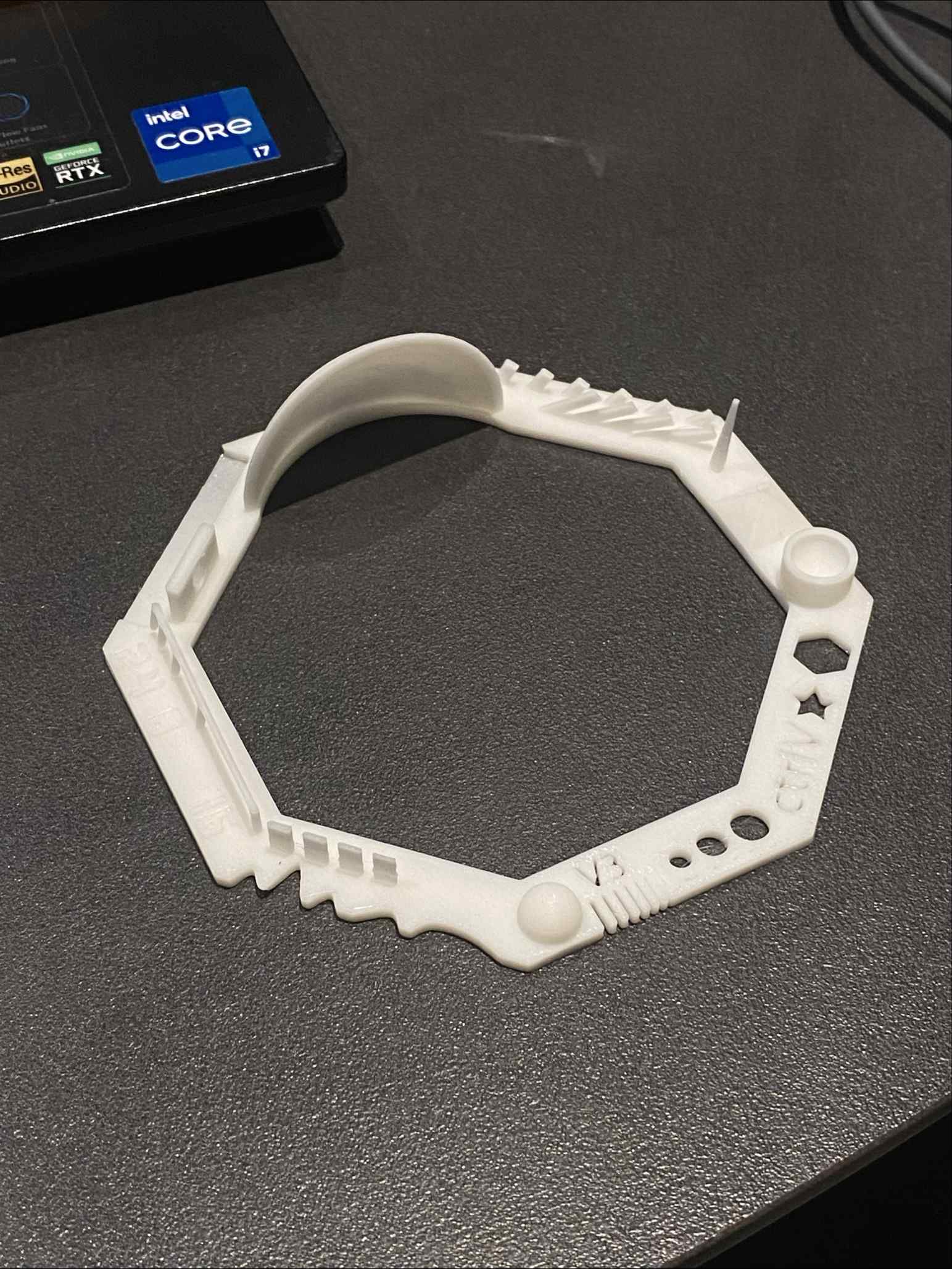
Test 1 — Bambu Studio setup, design rules reference, and printed result
Test 2 — Support, Overhang & Bridging
| Feature | Result |
|---|---|
| Support test | ✓ Pass |
| Scale test | ✓ Pass |
| Hole test | ✓ Pass |
| Diameter test | ✓ Pass |
| Bridging test | ✓ Pass |
| Overhang below 60° | ✓ Good quality |
| Overhang above 60° | ⚠ Passing quality |
| Pins: 2×10 mm, 2×20 mm, 2×30 mm | ⚠ Passing quality |
Overhangs beyond 60° and tall thin pins printed at passing quality without support. For critical applications requiring these features, adding supports or redesigning the geometry is recommended.
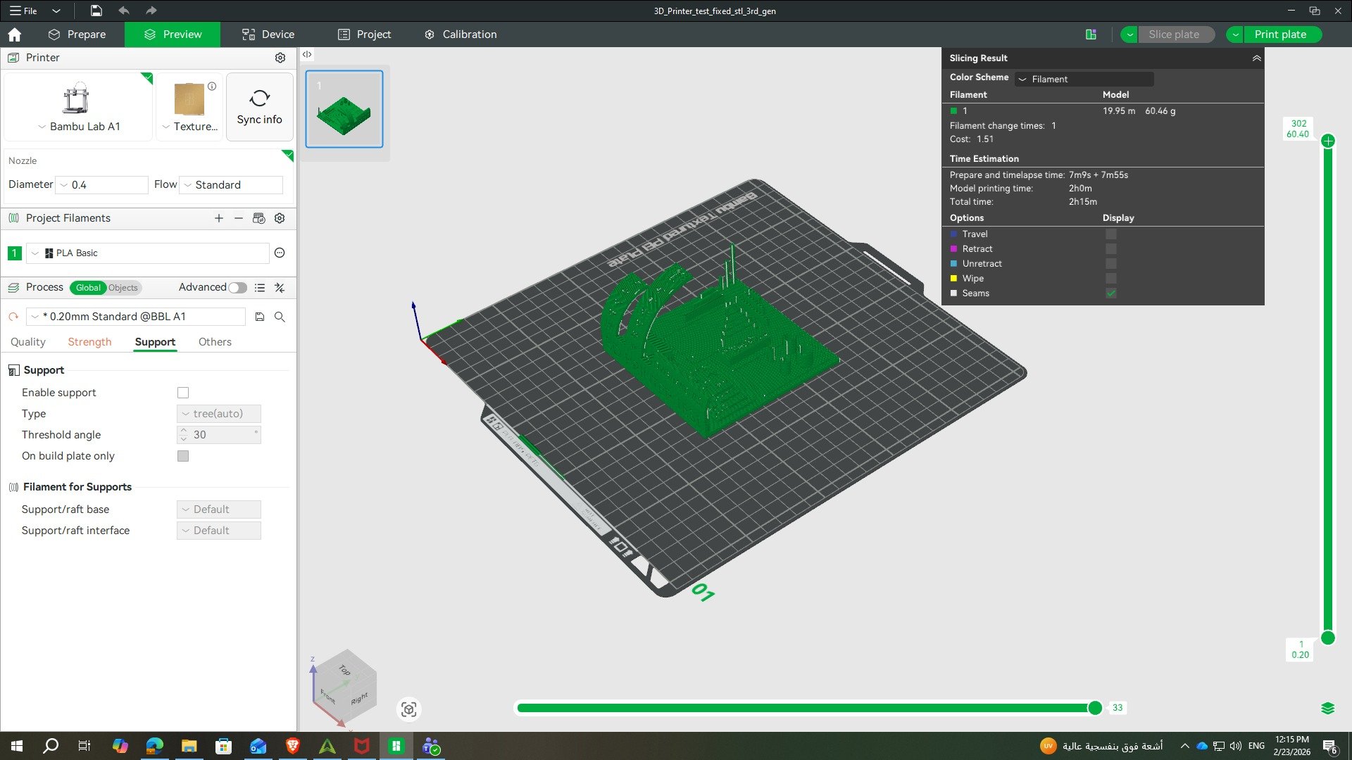
Test 2 — printed result and Bambu Studio slicing setup
3D Printing — Phone Holder
For the individual printing task, the object needed to be something that could not be made subtractively — meaning its geometry requires additive manufacturing to produce. I chose to design a phone holder, something I've always wanted for watching videos at my desk. The organic curved profile and integrated charging hole make it impractical to produce with traditional cutting or milling.
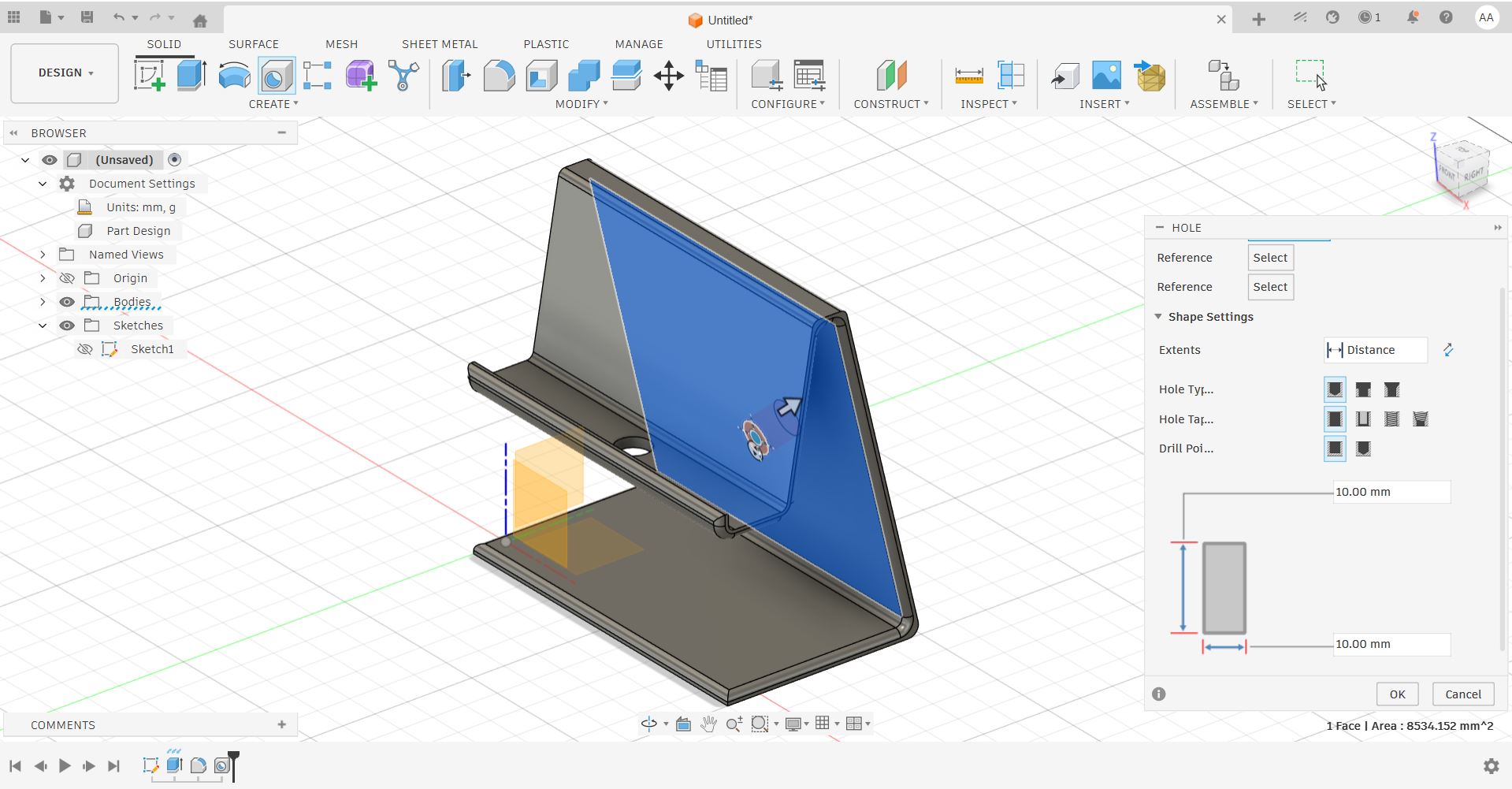
Design in Fusion 360
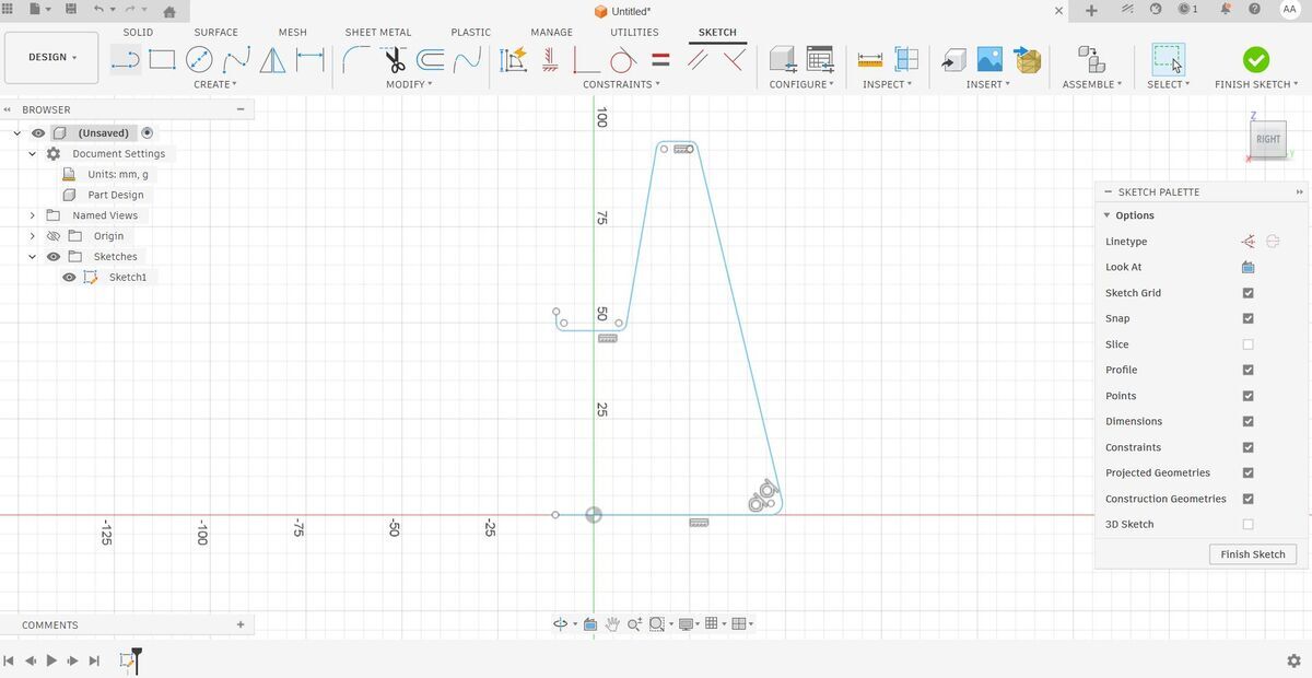
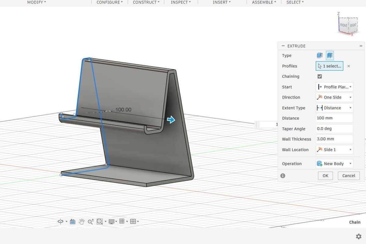
I designed the phone holder entirely in Fusion 360, following these steps:
- Sketched the side profile of the holder shape
- Extruded the sketch to give it depth and form
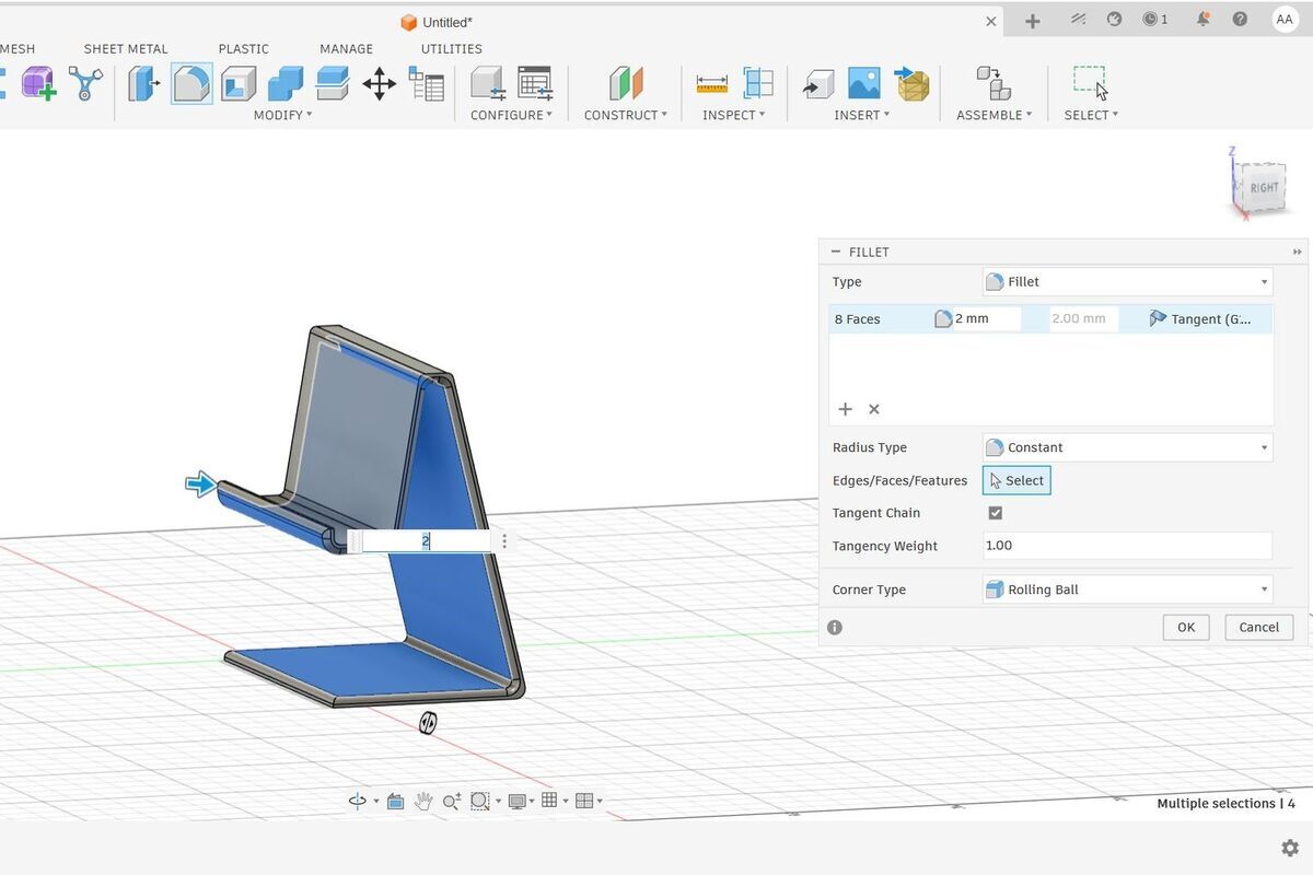
- Refined the edges using the Fillet tool for smooth, organic transitions
- Added a cutout hole to allow phone charging while in use
- Exported the final model as an STL file for slicing
Slicing & Print Settings
The STL was imported into the slicer and prepared for printing on the Bambu Lab A1.
A 15% infill was selected to keep the holder lightweight while maintaining enough structural rigidity to hold a phone securely. No supports were needed to handle the geometry.
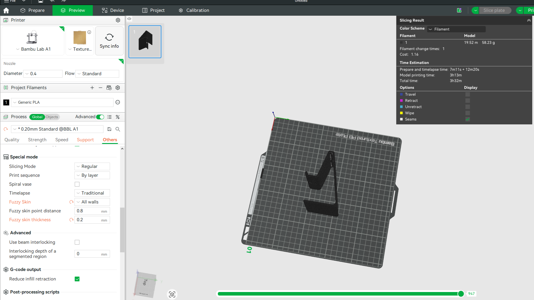
Slicer setup — Bambu Lab A1 settings
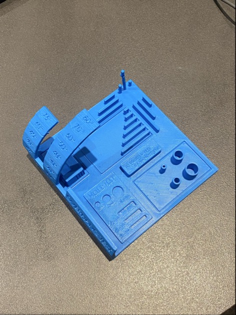
Print Result
The print completed successfully. The phone holder was clean, functional, and fit exactly as designed — including the charging cutout, which remained clear and accessible.
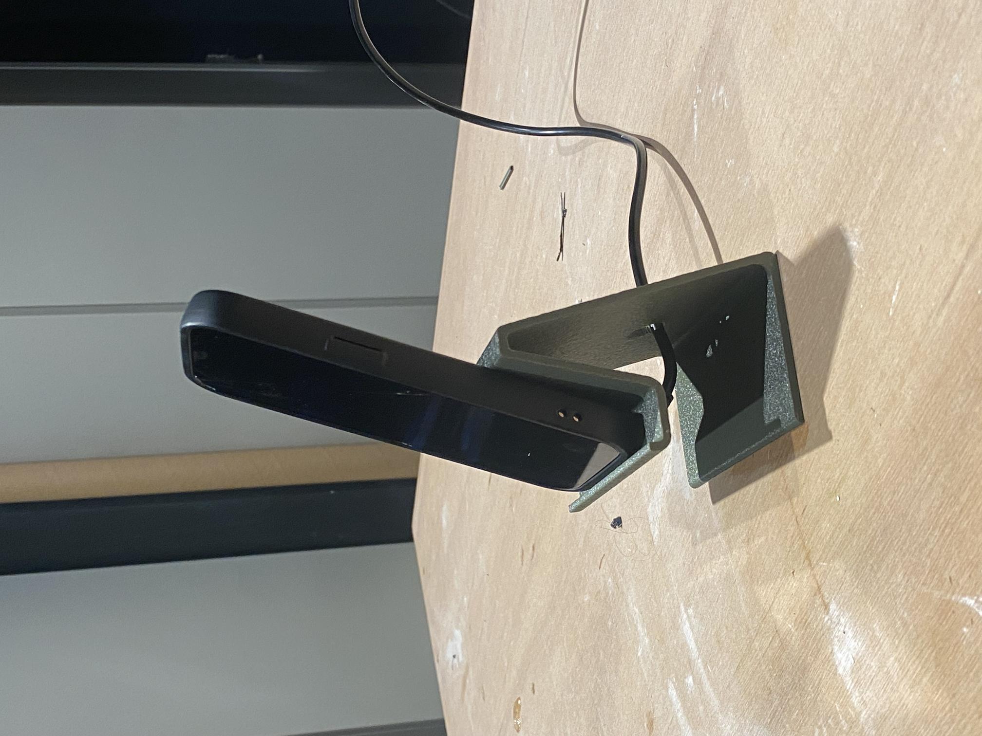
Bambu Lab A1 — Final result
Download the design file below to explore or modify the phone holder model.
3D Scanning — Motor Mount
For the scanning task, I used the Shining 3D EinScan-SP structured-light 3D scanner. I chose to scan a motor mount — a component I needed to replicate for a plotter project I am working on. Scanning an existing part allowed me to capture its precise geometry and produce a printable file without having to reverse-engineer it manually in CAD.
Machine
Shining 3D EinScan-SP — a desktop structured-light 3D scanner capable of capturing fine surface geometry with high accuracy. It uses a turntable-based workflow and dedicated EXScan software to align and merge multiple scan passes into a complete mesh.
Calibration
Before scanning, the EinScan-SP must be calibrated using its calibration board. This step ensures the scanner's structured-light pattern is correctly aligned and that distance measurements are accurate. Calibration is quick but essential — skipping it leads to misaligned scan merges and inaccurate geometry.
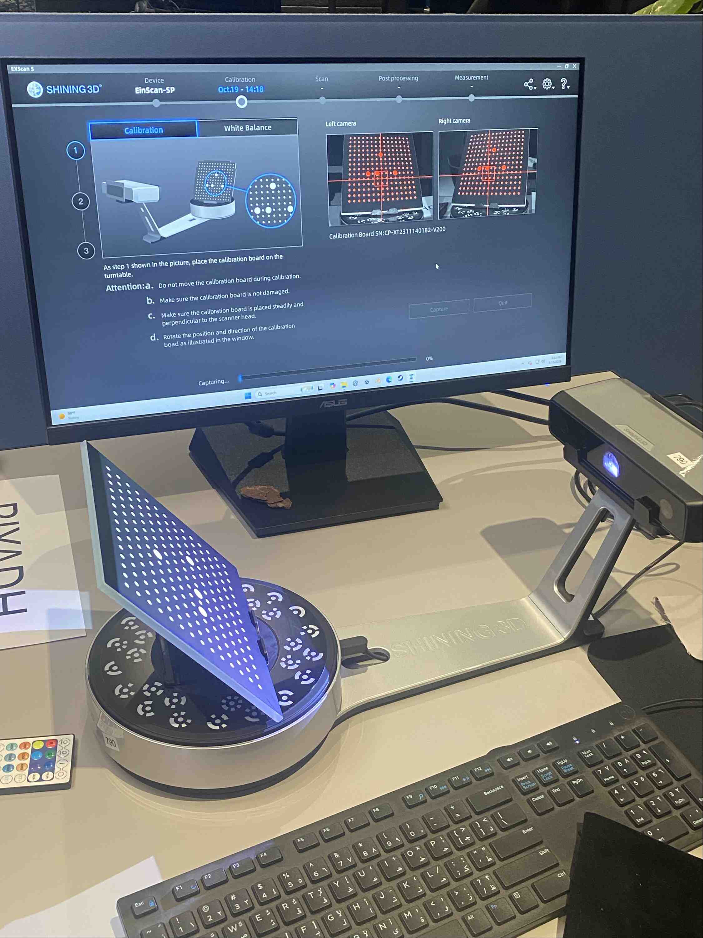
EinScan-SP calibration using the calibration board
Scanning — Two-Sided Capture
The motor mount was placed on the turntable and scanned from two sides to capture geometry that would otherwise be hidden in a single pass. The scanner rotates the turntable automatically and captures multiple frames per revolution, building up a point cloud for each side.
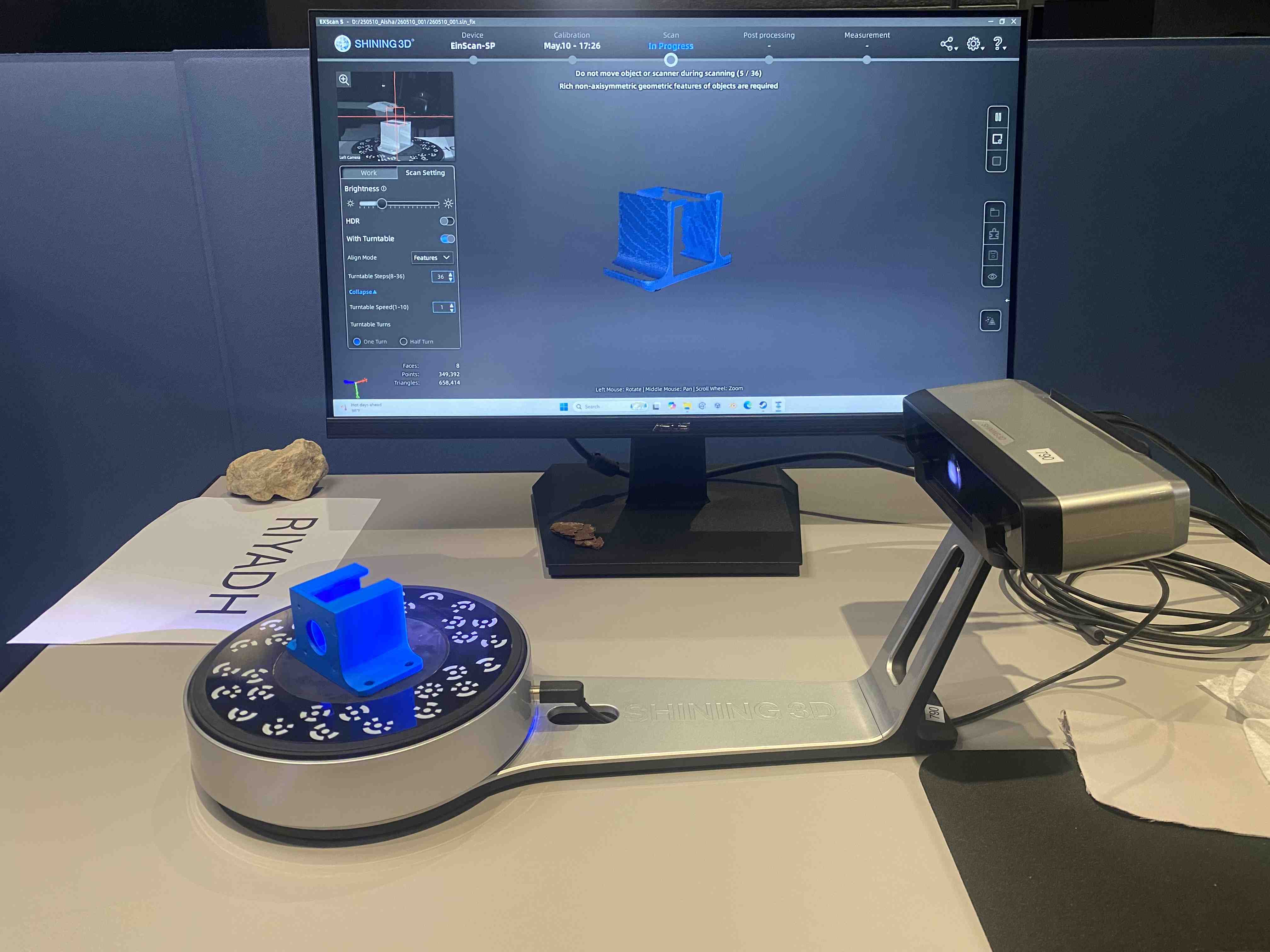
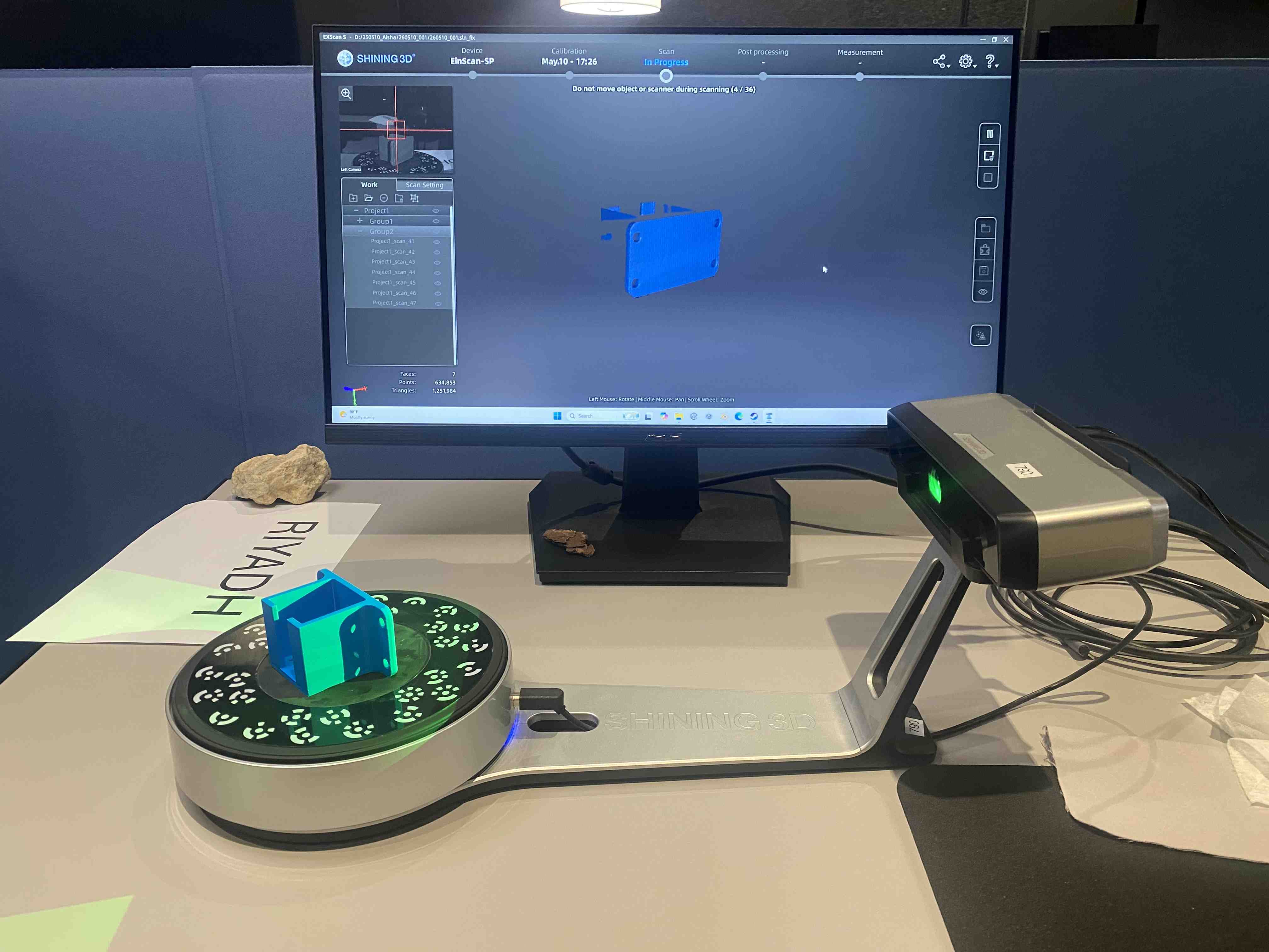
Side 1 and Side 2 of the motor mount — captured on the turntable
Grouping & Export
Once both sides were captured, they were grouped together in the EXScan software. The software aligns and merges the two scans into a single watertight mesh. The final model was exported as a 3MF file, ready for slicing and printing.
Scanning dark or shiny surfaces can cause reflections that confuse the scanner. For best results, matte spray (such as anti-glare powder) is often applied to the object before scanning — especially useful on metallic or glossy parts like motor mounts.
Scanning Process Video
Full scanning workflow — calibration, two-sided scan, and mesh grouping
Reflection
This week gave me a much deeper understanding of what 3D printing can and cannot do. Running the design rule tests before printing my own part was genuinely useful — knowing the machine's overhang limits, minimum feature sizes, and bridging capabilities helped me make better design decisions when modeling the phone holder.
Designing something that could not be made subtractively pushed me to think differently about form. The curved profile and internal geometry of the phone holder are straightforward for additive manufacturing but would be extremely difficult to achieve through cutting or milling. That distinction — additive vs. subtractive thinking — is something I'll carry into every fabrication decision going forward.