Assignment Tasks
🔬 Group Assignment
- Complete lab safety training
- Characterize the laser cutter — focus, power, speed, rate, kerf, joint clearance, and types
👤 Individual Assignment
- Cut something on the vinyl cutter
- Design, laser cut, and document a parametric construction kit accounting for kerf
Extra Credit
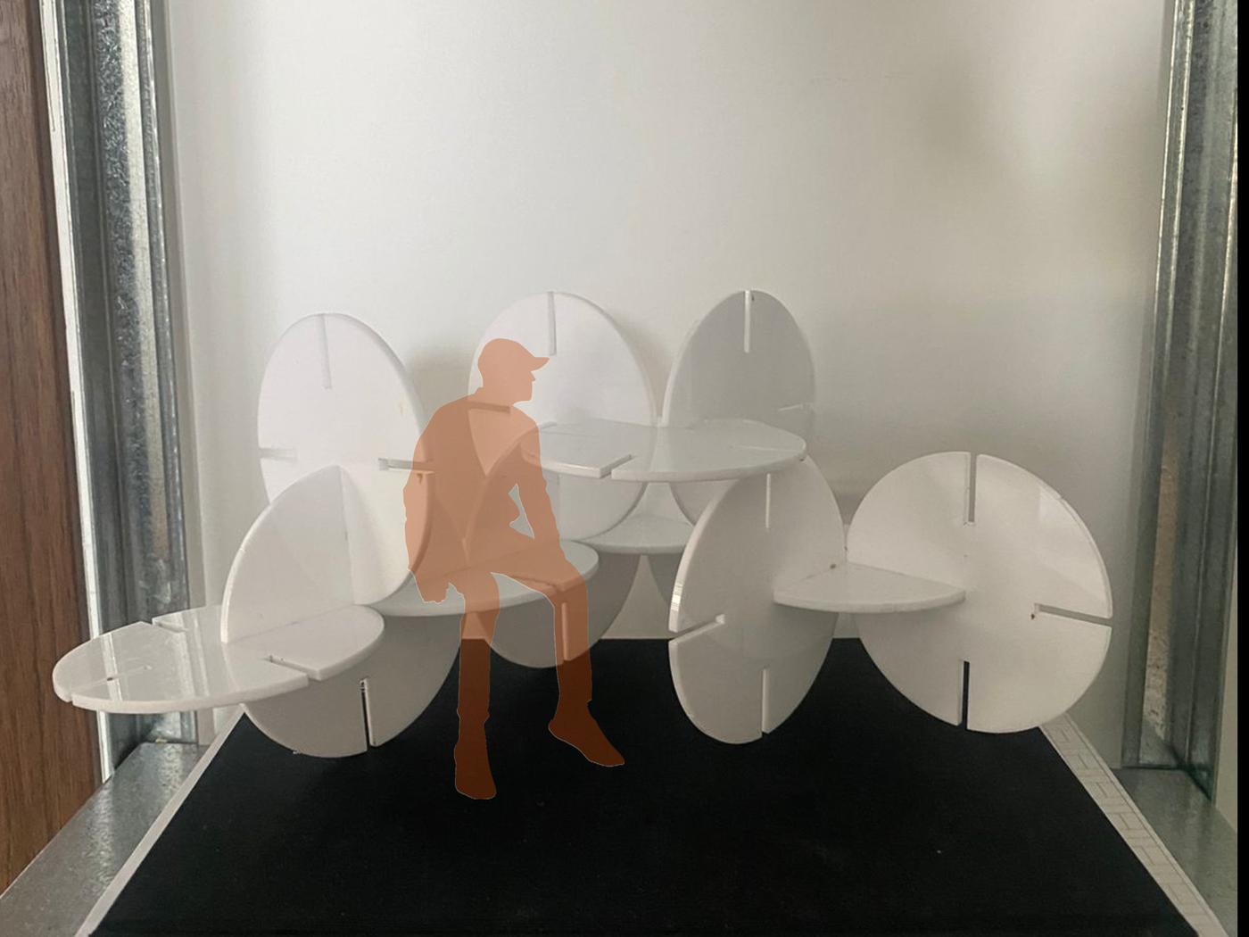
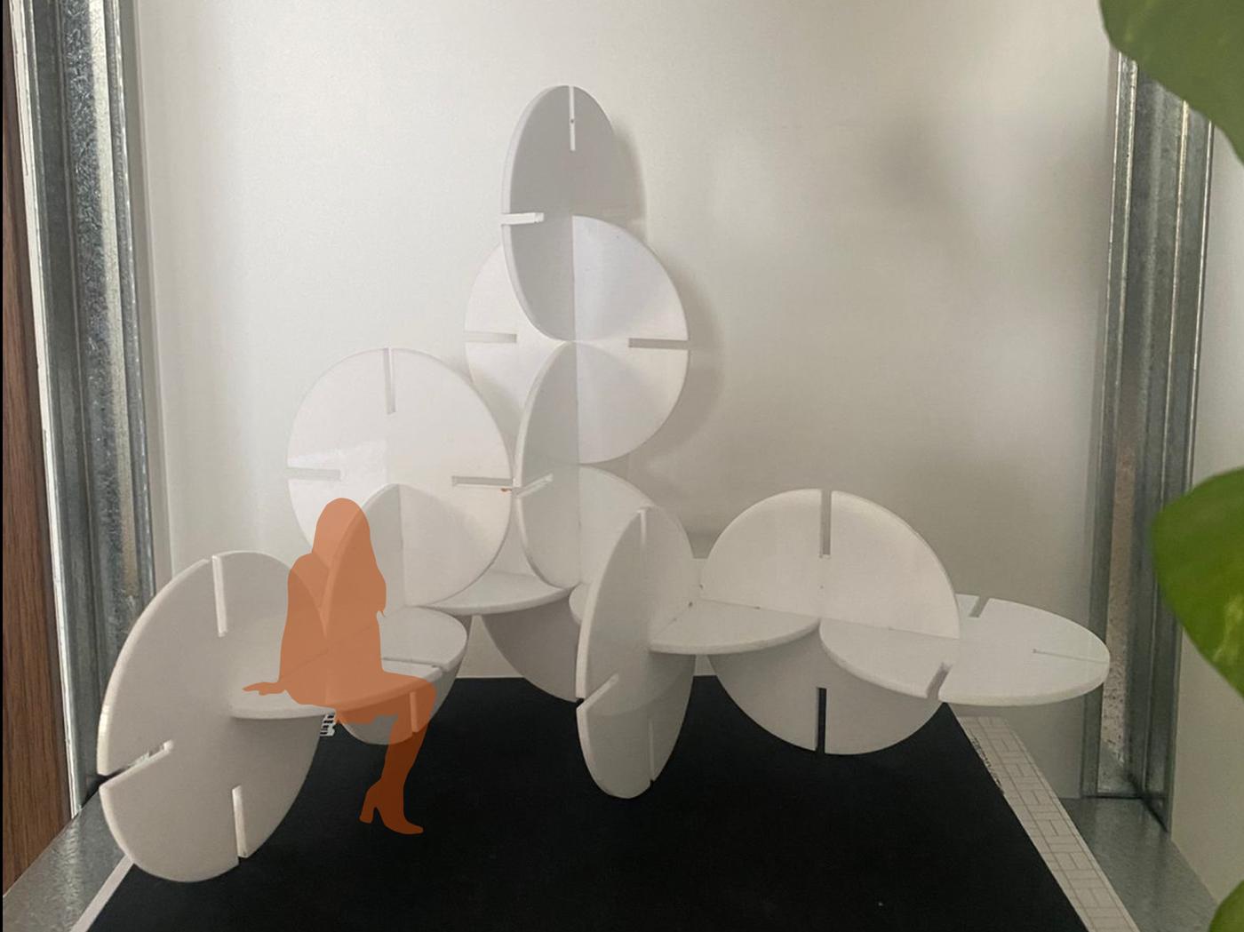
- Design to be assembled in multiple ways
- Include elements that aren't flat
- Engrave as well as cut
Vinyl Cutter
What is a Vinyl Cutter?
A vinyl cutter is a computer-controlled machine that uses a small blade to cut shapes and designs from sheets of vinyl material. It follows vector paths generated from design software, making it ideal for producing precise stickers, decals, and signage without the need for heat or chemicals.
Creating the Design
I downloaded Inkscape to prepare the file for vinyl cutting. Inkscape is a free, open-source vector graphics editor that allows designs to be exported in formats compatible with cutting machines.
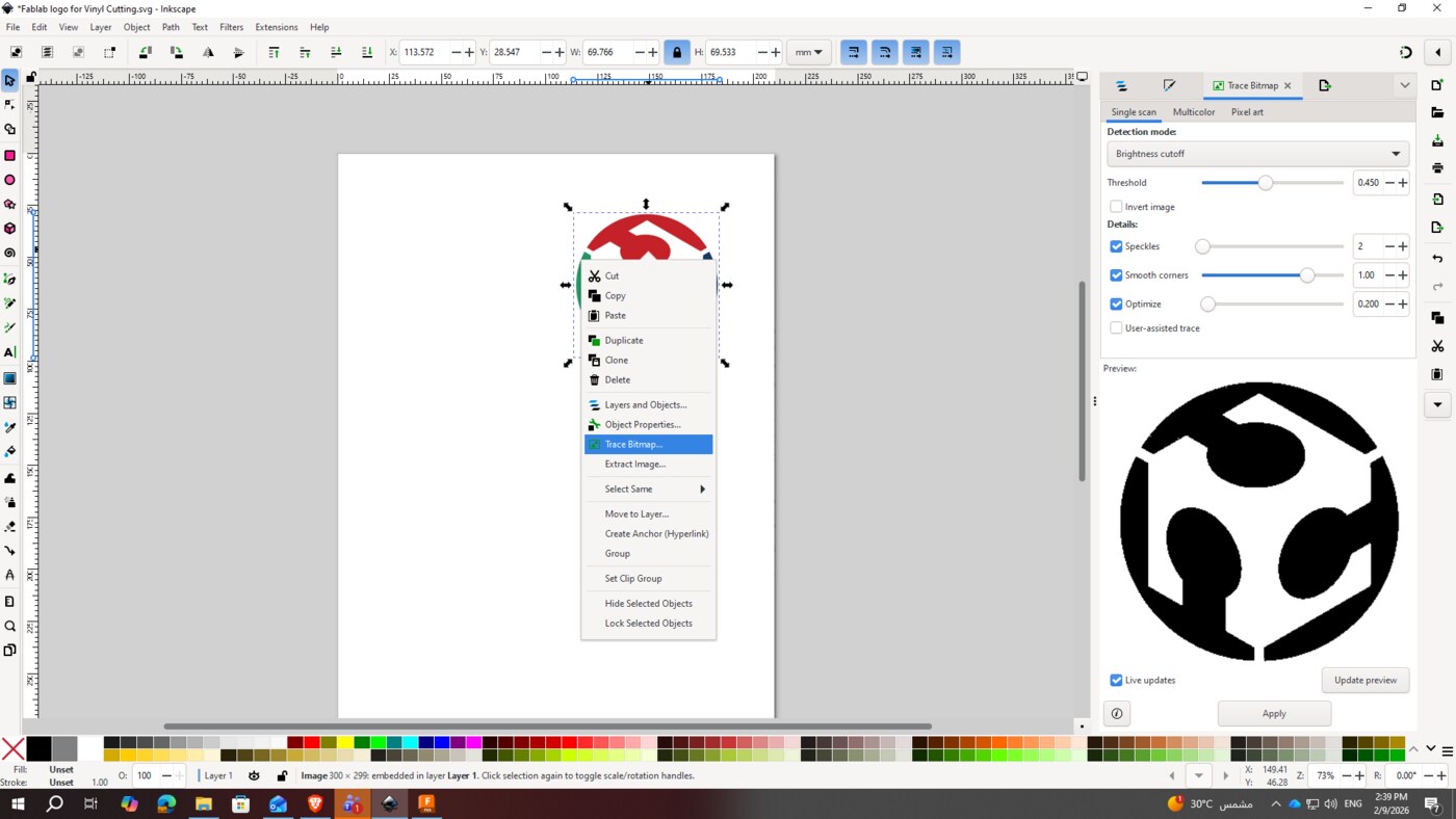
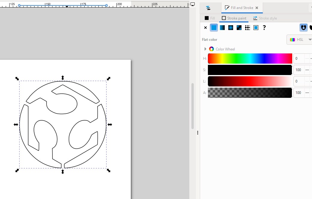
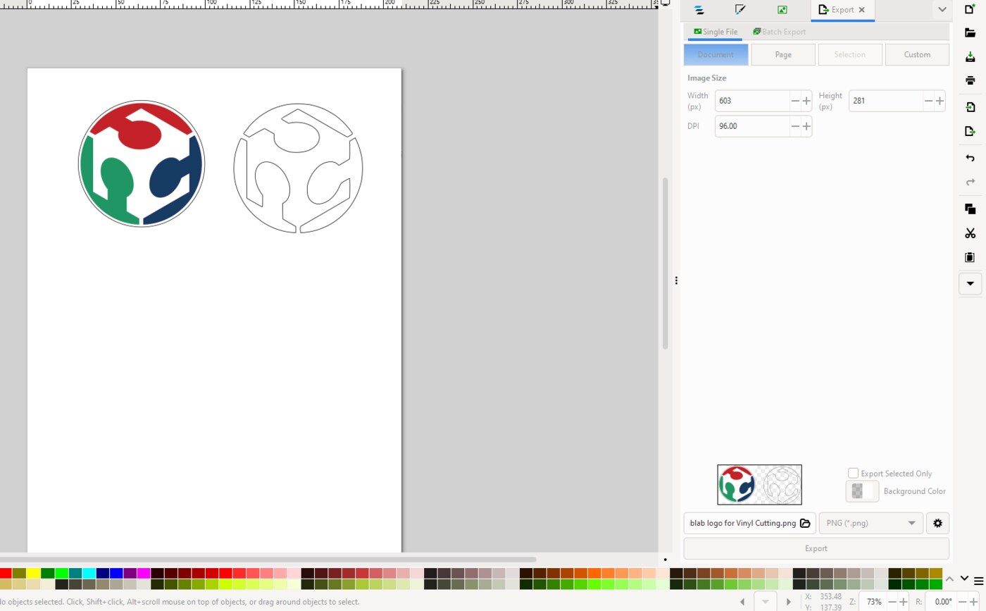
I imported the Fab Lab logo into Inkscape by dragging it onto a new page, then converted the image into vector paths using Path → Trace Bitmap. After tracing, I cleaned up the design using stroke paint settings to ensure clean, cuttable outlines, then exported the final design as a DXF file for cutting.
Cutting the Vinyl
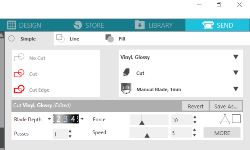
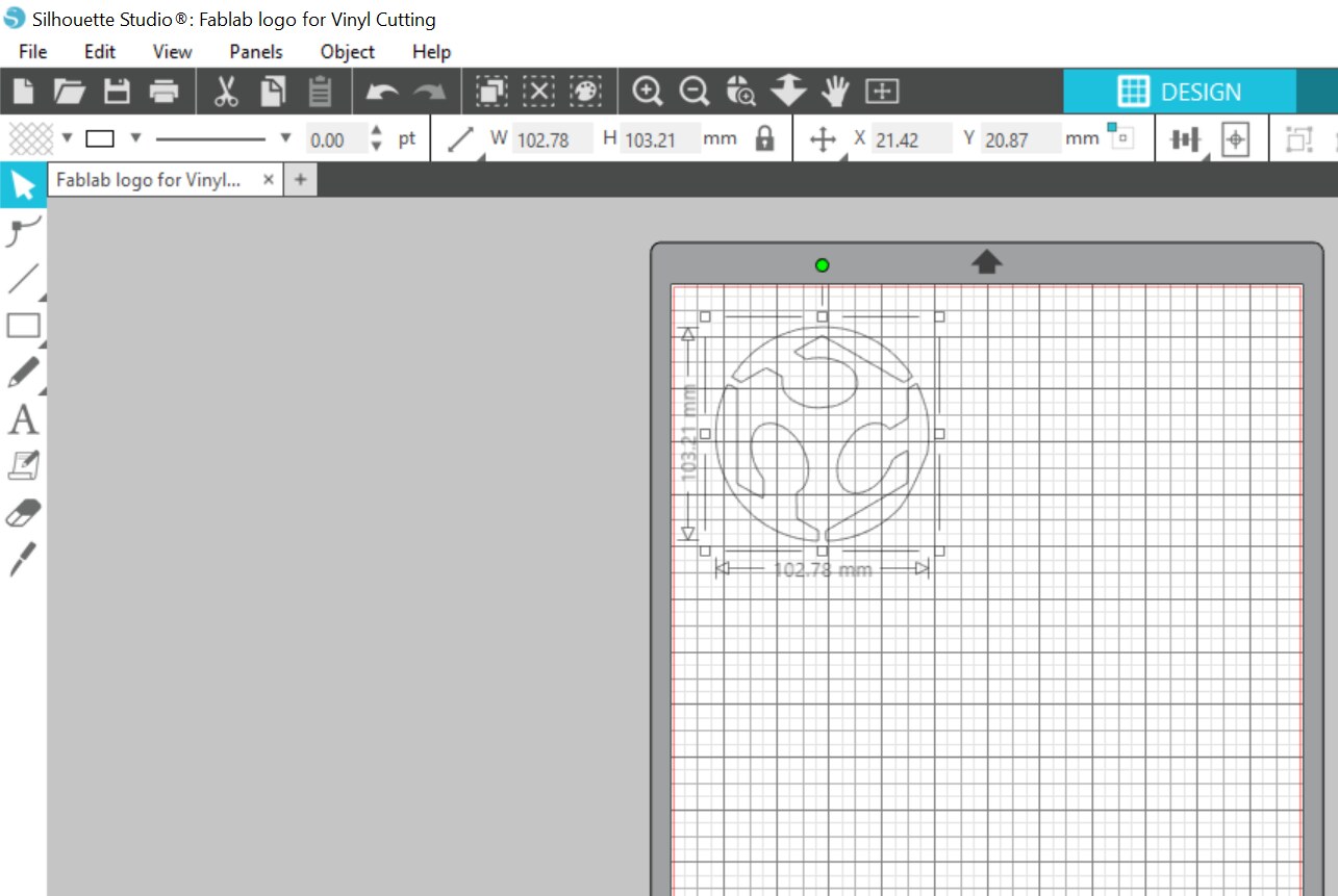
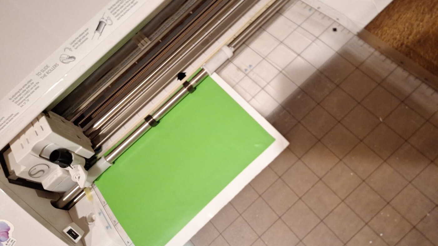
The DXF file was imported into Silhouette Studio software. The design was then cut using standard vinyl cutting settings on the Cameo 4 vinyl cutter — a professional desktop cutter capable of handling a wide range of materials with high precision.
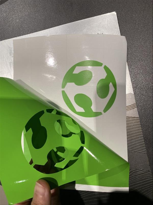
Final Vinyl Sticker
After cutting, the excess vinyl was carefully weeded away and the finished sticker was transferred to its final surface.
Laser Cutting — Parametric Construction Kit
What is a Laser Cutter?
A laser cutter is a computer-controlled machine that uses a focused beam of light to cut or engrave materials such as acrylic, wood, cardboard, and fabric. The laser burns or vaporizes the material along a programmed path, producing precise cuts with clean edges.
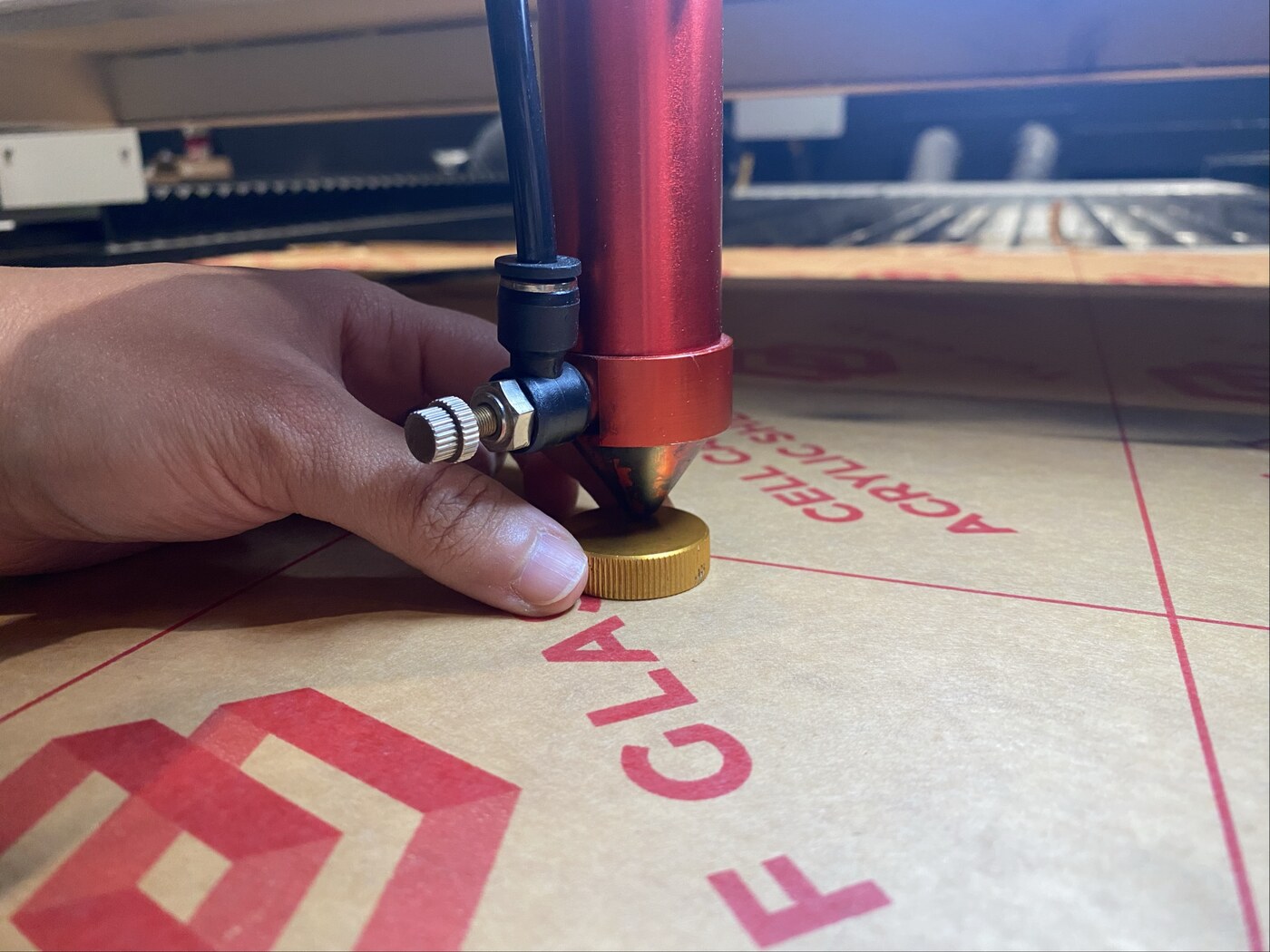
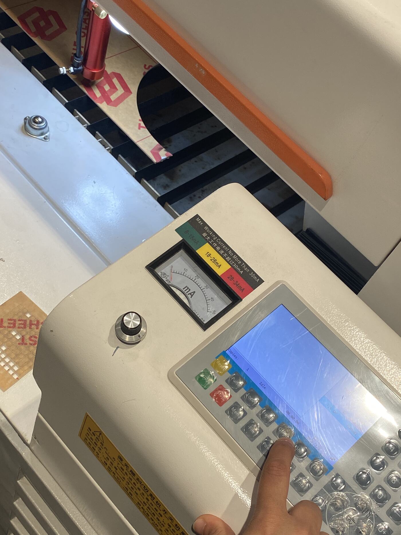
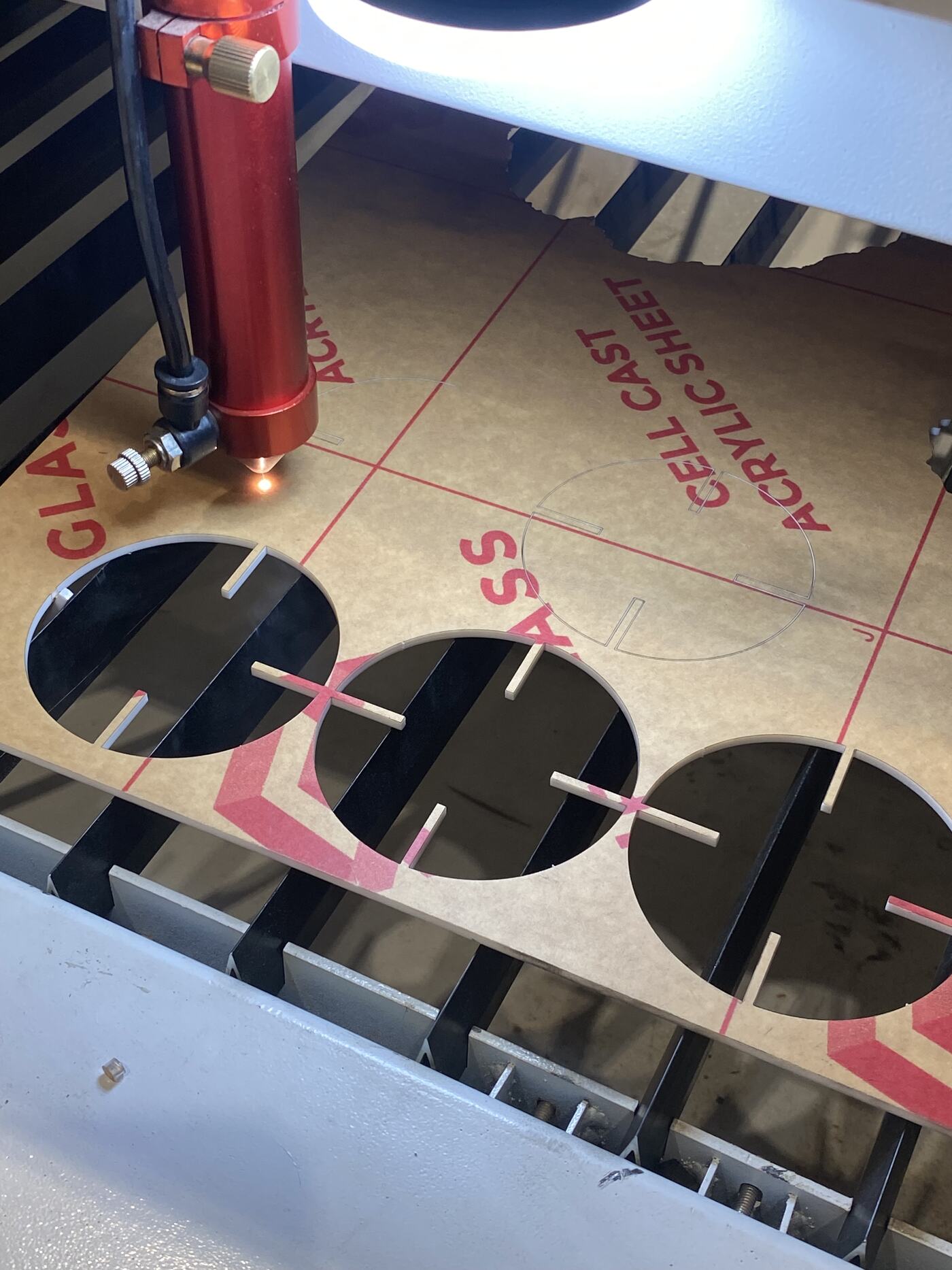
Machine Setup & Material Preparation
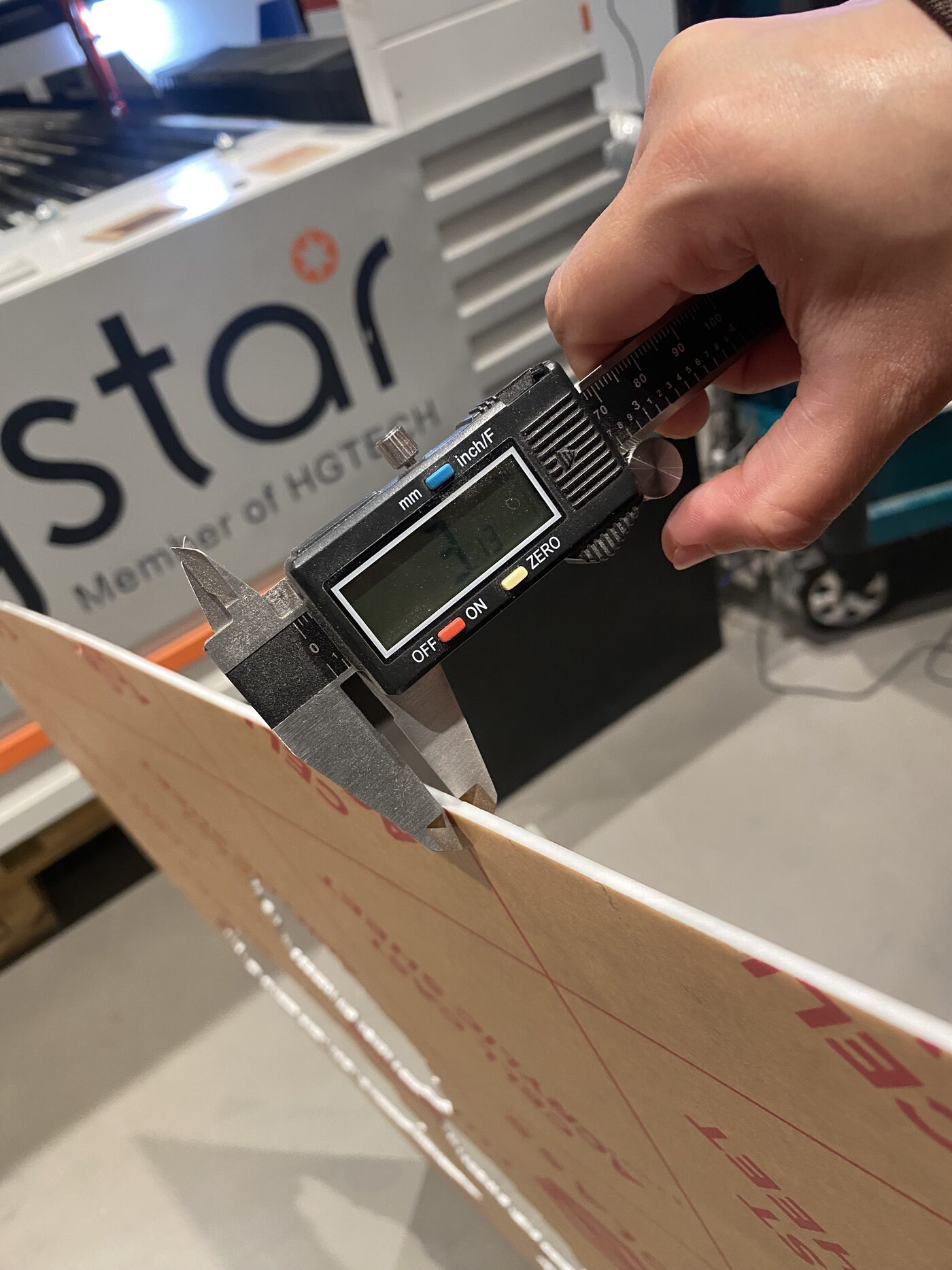
Before running any job on the laser cutter, I followed proper setup procedures. I checked the acrylic sheet thickness, placed it flat on the laser bed, adjusted the nozzle height based on the material, and set the origin point before starting the job.
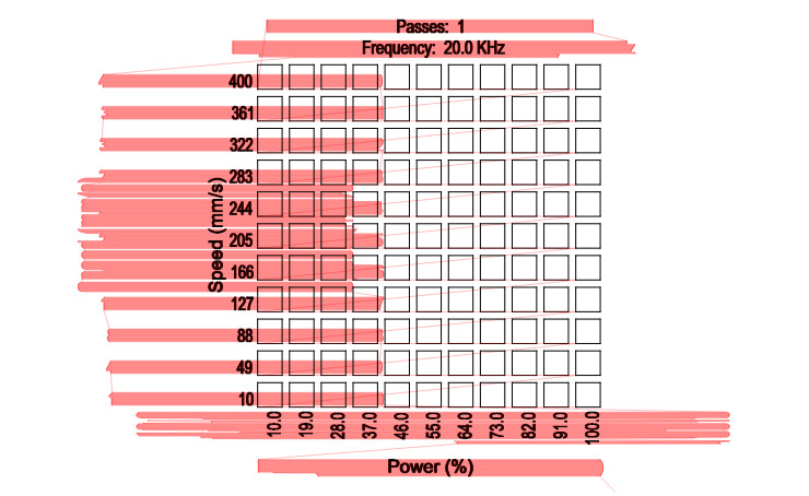
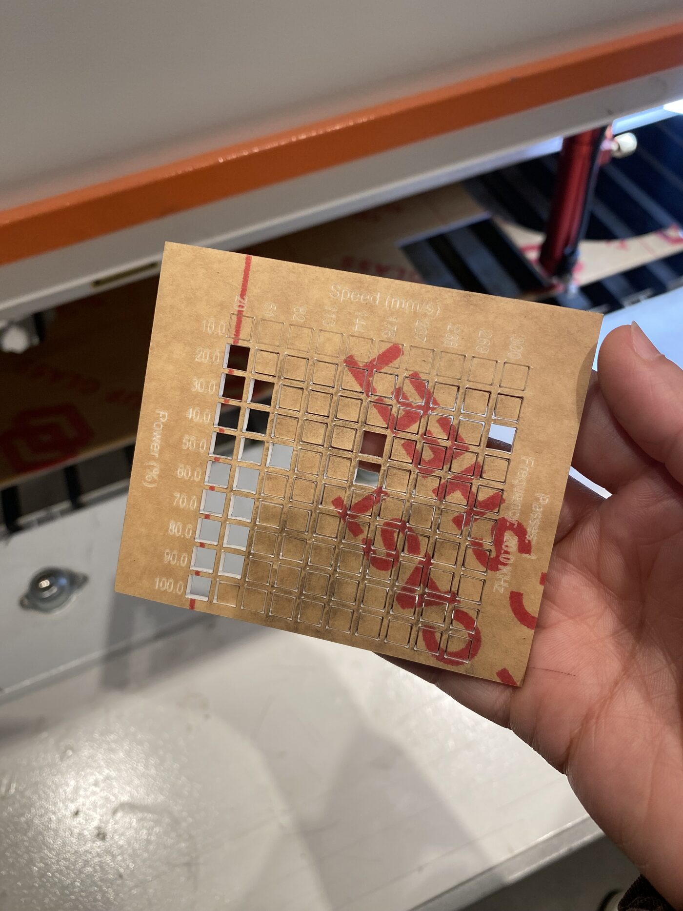
Power & Speed Testing
To find the optimal cutting settings for the material, I ran a power and speed test on a 3mm acrylic sheet before committing to the full design. After testing multiple combinations, the best result was achieved at:
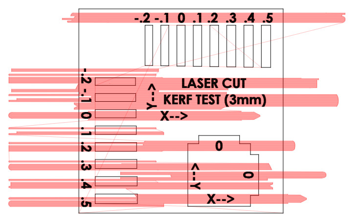
Kerf Measurement
What is Kerf?
Kerf refers to the width of material removed by the laser beam during cutting. Because the laser burns away a small amount of material, the actual cut piece is slightly smaller than the designed dimension. Accounting for kerf is essential when designing interlocking or press-fit joints, as even a fraction of a millimeter can determine whether pieces fit together correctly.
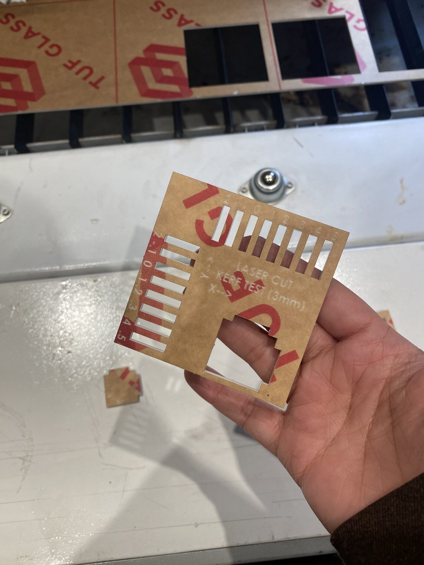
I ran a dedicated kerf test for the 3mm acrylic sheet to determine the ideal slot width for an interlocking press-fit mechanism. The best result was:
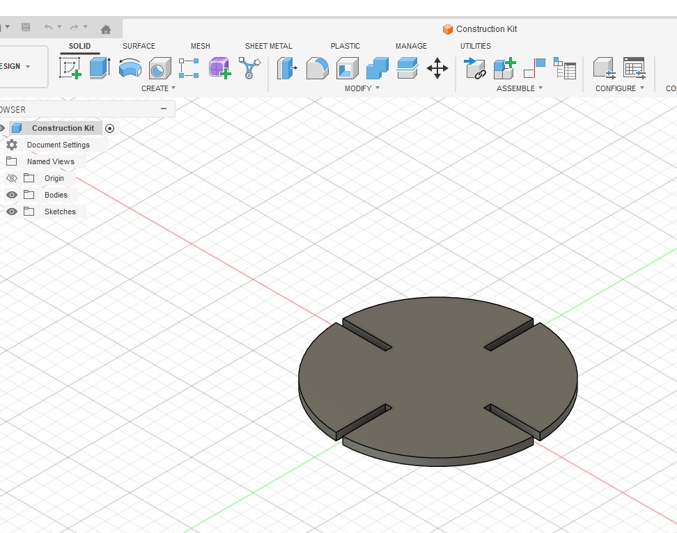
Parametric Design in Fusion 360
What is Parametric Modeling?
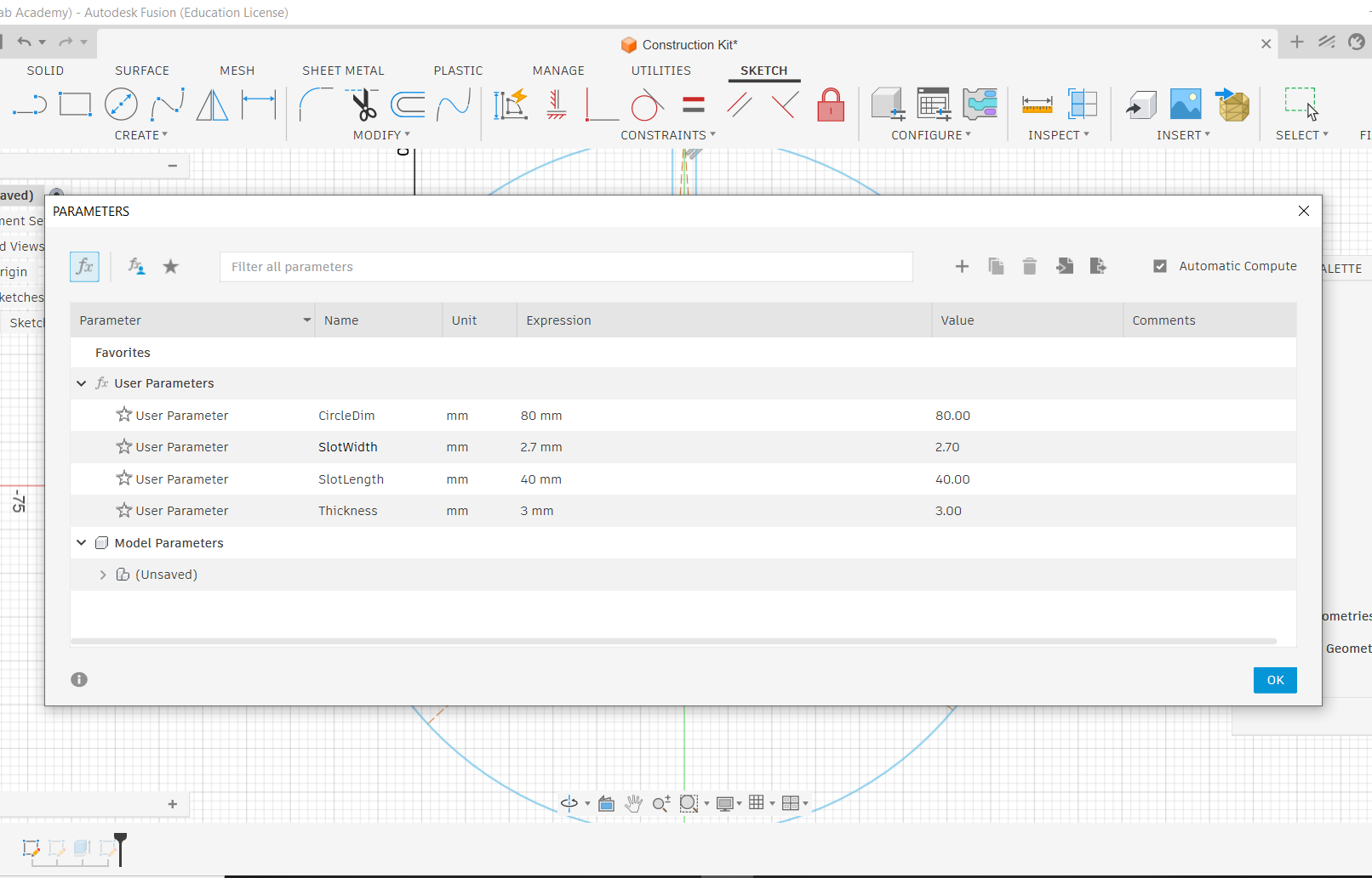
Parametric modeling is a design approach where the geometry of a part is driven by defined parameters — numerical values such as diameter, thickness, or slot width. When a parameter is updated, the entire model adjusts automatically. This makes it easy to adapt designs for different materials or tolerances without redrawing from scratch, which is especially valuable in digital fabrication where material properties vary.
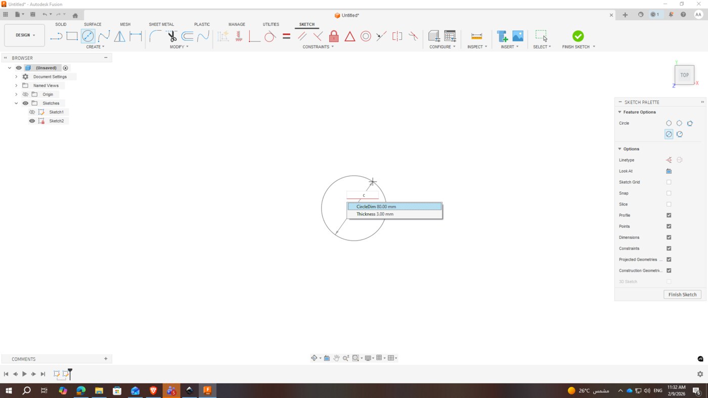
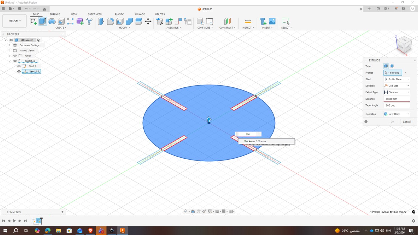
For the construction kit design, I used Fusion 360 and defined all key dimensions as parameters from the start, so the design could be easily adjusted for different material thicknesses or kerf values.
Design Parameters
| Parameter | Value | Purpose |
|---|---|---|
| Diameter | 80 mm | Overall size of each kit piece |
| Slot Thickness | 40 mm | Depth of the interlocking slot |
| Kerf | 0.30 mm | Compensates for material removed by the laser |
| Extrusion (Material Thickness) | 3 mm | Matches the acrylic sheet thickness |
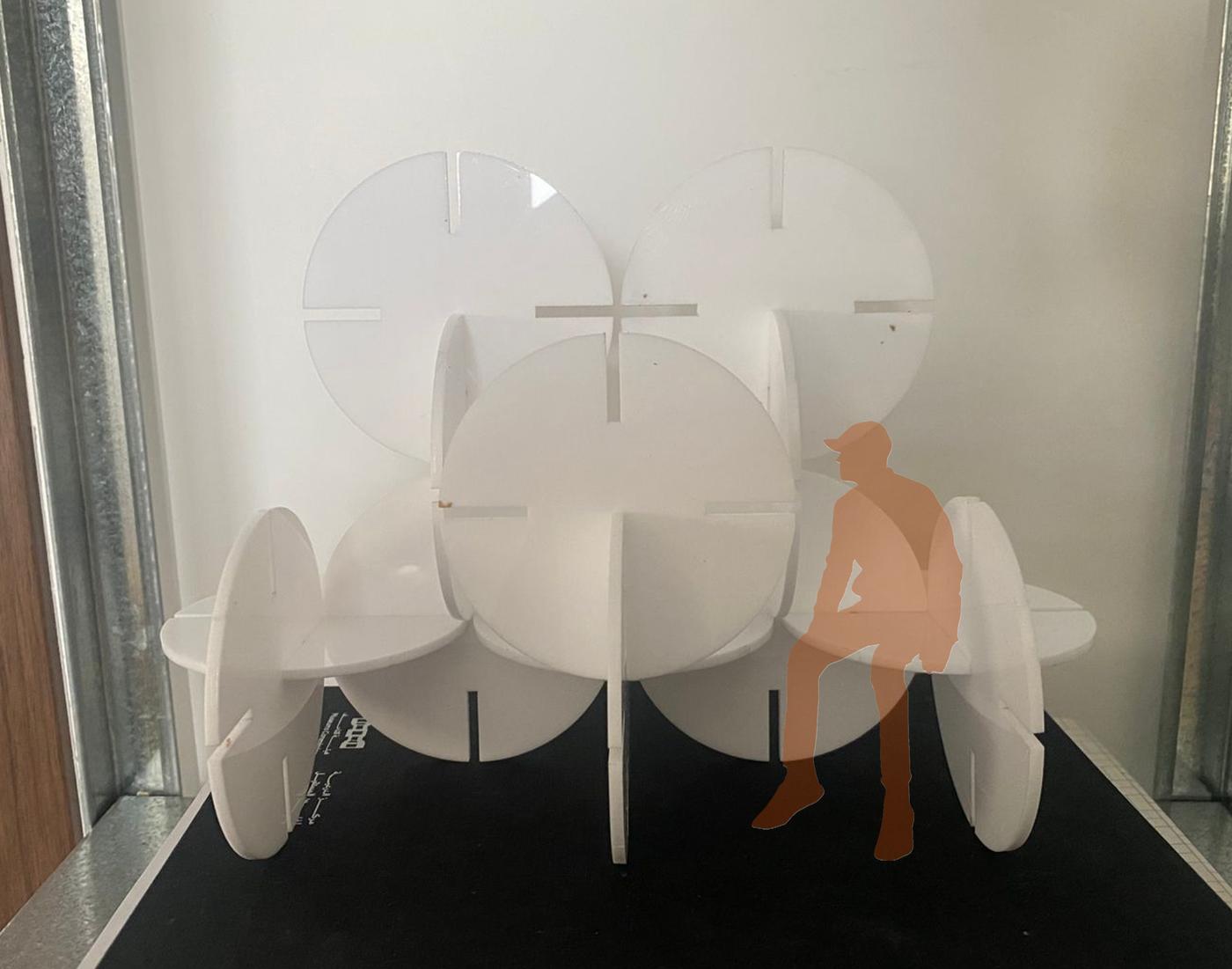
Cutting & Assembly
After finalizing the design in Fusion 360, I exported the file and ran the laser cutting job with the tested power and speed settings. The pieces were then assembled to test the press-fit joint quality.
Download the Fusion 360 source file to explore or modify the parametric construction kit design.
Reflection
This week introduced me to two very different cutting workflows — vinyl cutting and laser cutting — each requiring its own preparation, software, and attention to detail. The vinyl cutting process was relatively straightforward once the vector file was clean, but it reinforced how important file preparation is before any fabrication step.
The laser cutting portion was more technically demanding. Running power and speed tests before committing to the full design felt like an important habit to build — it saved material and gave me confidence in the final result. The kerf test in particular was a valuable lesson: even a difference of 0.1mm in slot width can determine whether a press-fit joint holds firmly or falls apart.
Using parametric modeling in Fusion 360 made the process feel more robust. Knowing that I could change the material thickness or kerf value and have the entire design update automatically is something I'll carry into every future fabrication project.