What We Were Asked to Do
Assignment
Model (raster, vector, 2D, 3D, render, animate, simulate, …) a possible final project, compress your images and videos, and post a description with your design files on your class page.
What I Designed
For this week's assignment I used the opportunity to work on two components of my final project — Lamperto, a smart ambient lamp. The assignment required using at least two different software tools for 2D and 3D design, so I used:
- AutoCAD — for 2D design of the upper laser-cut acrylic enclosure (the visible box that houses the LEDs)
- Fusion 360 — for 3D modeling of the wiring enclosure (the 3D-printed housing that holds the PCB and connects to the structure)
Design Goals
The 2D AutoCAD drawing needed to produce flat panels for the laser-cut upper box — all five sides with correct hole positions. The 3D Fusion 360 enclosure needed to house the PCB, provide openings for the power cable and toggle switch, support a rod-and-nut structural system, and lock to a lid with 2mm clearance.
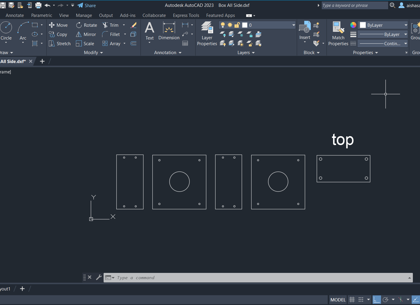
Laser-Cut Upper Box (AutoCAD)
I used AutoCAD software to draw the flat panel layout for the upper acrylic enclosure. The design consists of five panels — front, back, two sides, and top — each laid out flat as a .dxf file ready to send directly to the laser cutter.
Wiring Enclosure (Fusion 360)
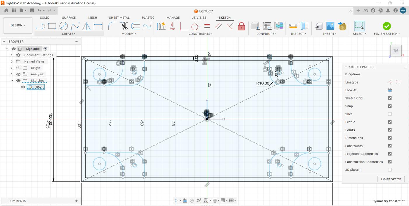
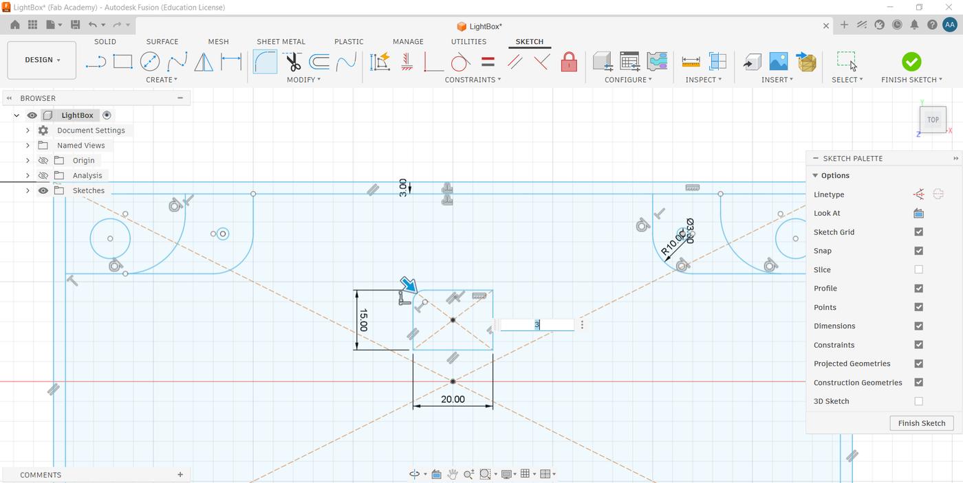
Sketching the Base Profile
I started with a 2D sketch, keeping all the integration constraints in mind from the beginning — rod insert positions, the cable opening location, the switch cutout. Getting these dimensions right in the sketch meant the rest of the design could be built from a single source of truth.
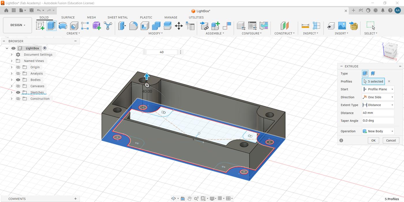
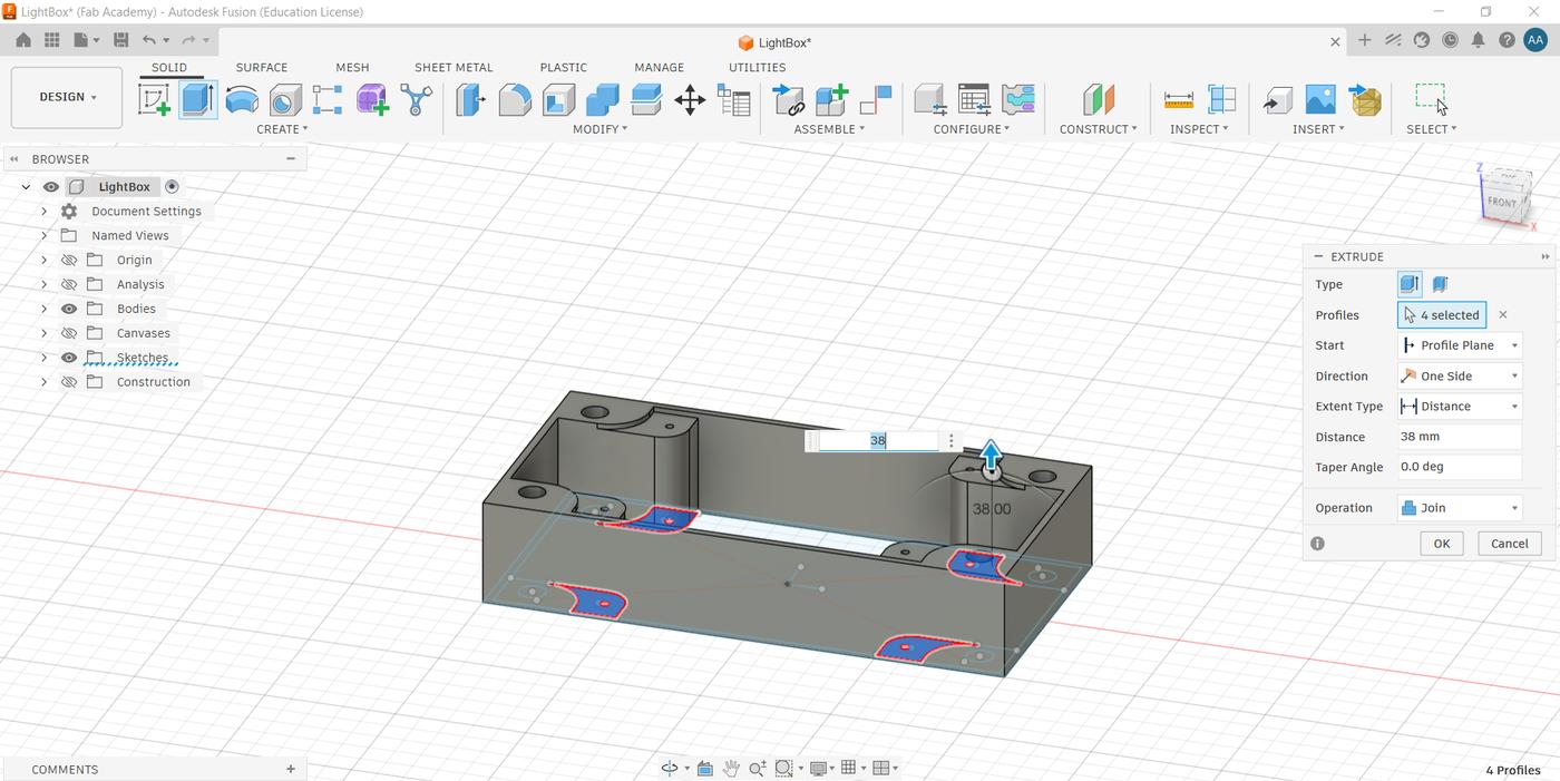
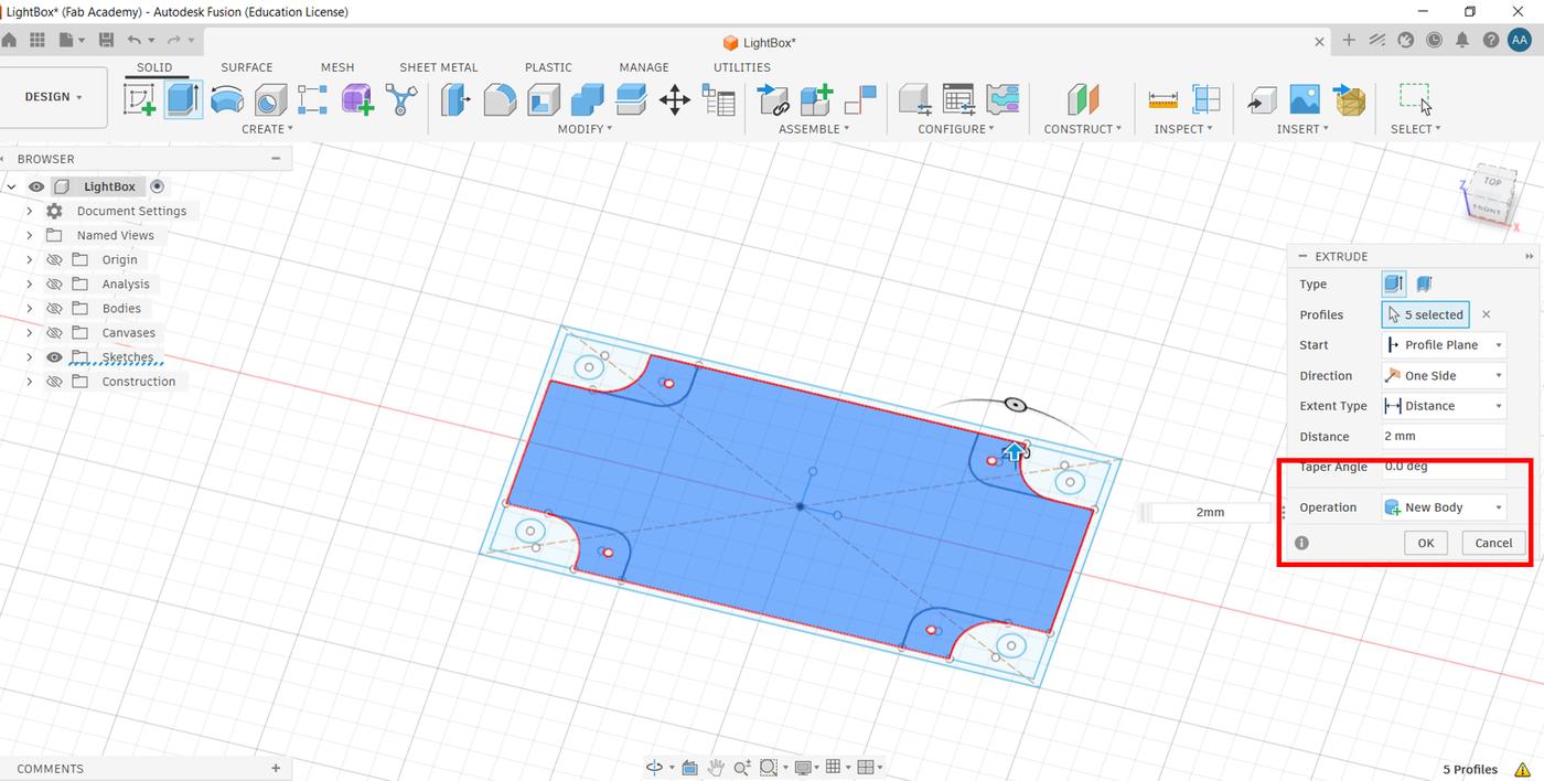
Extruding the Enclosure Body
From the sketch, I used the Extrude tool to build up the enclosure walls and rod openings as the first operation. I then extruded the lid resting ledge as a second step — I needed to leave a deliberate gap of 2.0mm to match the lid thickness so it would sit flush when closed. I then extruded the lid outline as a completely separate body by enabling New Body in the extrude settings, so the lid and enclosure remain independent objects in the same file.
Cable Opening
Still working from the same original sketch, I used the base outline to create the cable opening — applying the Fillet tool first to soften the edges before extruding the cutout.
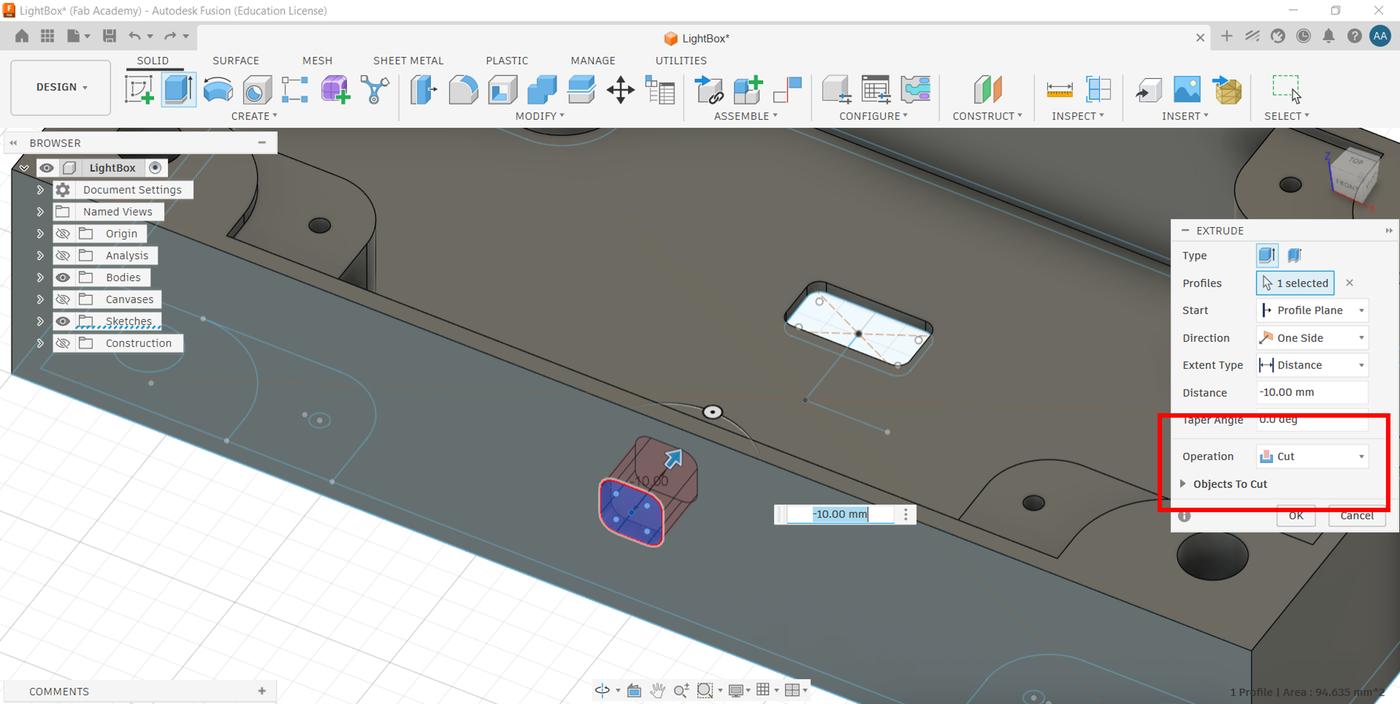
Switch Opening
To create the toggle switch cutout, I added a new sketch directly on one of the enclosure's side faces. I drew the switch profile, then used the Extrude tool with the Cut operation selected to punch the opening through the wall. This kept everything clean.
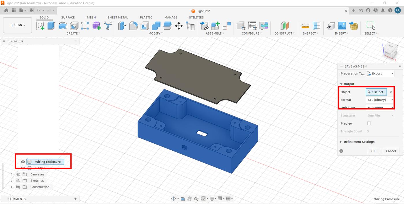
Exporting to STL
Once both bodies (enclosure and lid) were complete, I right-clicked each body in the browser panel and selected Save as Mesh to export them individually as STL files, ready for 3D printing.
AutoCAD vs. Fusion 360 — Which Worked Better?
Using both tools in the same week made it easy to compare them directly. AutoCAD is the right tool for a specific job: producing clean, precise 2D DXF files for laser cutting. It's fast for flat geometry and the output is exactly what a laser cutter expects. But it's purely 2D — there's no way to visualize how the panels will look assembled, and any 3D work requires switching to a different application entirely.
Fusion 360 felt more convenient overall for a project like Lamperto, for several reasons:
- Parametric design — dimensions are driven by constraints, so changing one value updates the entire model automatically without redrawing anything.
- Everything in one environment — 2D sketches and 3D bodies live in the same file. There's no need to switch tools or convert file formats mid-workflow.
- Non-destructive timeline — every operation is recorded in a history timeline, so I could go back and edit an earlier sketch or extrude without starting over.
- Direct STL export — right-clicking a body and choosing Save as Mesh outputs a print-ready STL with no intermediate steps.
- 3D preview — being able to see the enclosure in 3D while still editing the sketch caught alignment issues I wouldn't have spotted in a 2D drawing.
Verdict
AutoCAD is the right choice when the output is a flat DXF for a laser cutter and nothing else is needed. For a project that combines 2D and 3D work, Fusion 360's integrated parametric environment makes it significantly more efficient — fewer tool switches, fewer file conversions, and less risk of inconsistency between the sketch and the final 3D form.
Compressing Images & Video
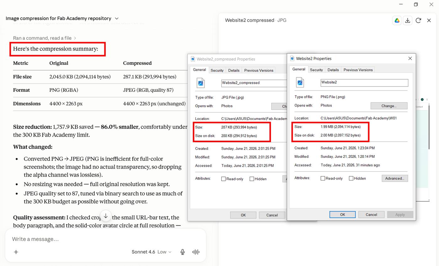
Part of this week's assignment was to compress images and videos before posting them. Documentation for Fab Academy involves a large number of images and videos, which can quickly make a website slow and difficult to use. To keep things performant, I used Claude (Anthropic) as an AI tool:
Image compression prompt: "Compress the attached image to 300 KB or less while maintaining the highest possible visual quality for Fab Academy Git repository limits, then report original size, compressed size, size reduction (KB and %), any changes to dimensions/resolution/quality settings, and a brief assessment of visible quality differences, ensuring the result loads quickly and stays clear and readable for web documentation."
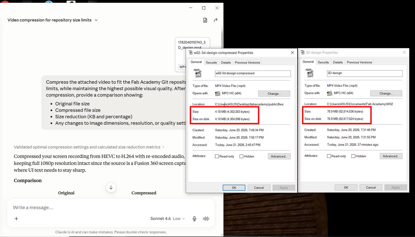
Video compression prompt: "Compress the attached video to fit Fab Academy's Git repo size limits at the highest visual quality possible, then report original size, compressed size, size reduction (KB and %), and any changes to dimensions/resolution/quality settings."
Design Walkthrough
A screen recording of the full Fusion 360 design process from sketch to 3D.
Downloads
The STL files for the enclosure body and lid, ready to slice and print.
⬇ Download Enclosure STL Files ZIP · 25 KBWhat I Learned
Working with two different tools in the same week gave me a clearer sense of where each one belongs. AutoCAD did exactly what it needed to for the laser-cut panels — precise, flat, clean DXF output. But Fusion 360's parametric environment made it the stronger choice for anything that involves 3D assembly, constraints, and iteration.
The biggest shift in Fusion 360 was learning to think in constraints before shapes. By building all the integration requirements into the sketch — rod positions, clearances, ledge heights — I could extrude everything from a single source rather than patching things together later. Using New Body in the extrude settings let me keep the lid and enclosure in the same design file while still exporting them as separate STLs. And planning for the 2mm lid clearance upfront saved me a reprint — a small decision in the sketch that would have been painful to fix after the fact.