Group Assignment
use the test equipment in your lab to observe the operation of an embedded microcontroller
Introduction
This week, we used Fab Lab Rwanda’s test equipment—oscilloscope, logic analyzer, function generator, multimeter, and power supply—to observe and analyze signals from a microcontroller circuit. We programmed an ESP32 and measured its digital and analog signals using these tools. With the logic analyzer we read the digital lines of the board and decoded the signals, which is the minimum the group assignment asks for. The hands-on experience helped us understand how oscilloscopes, logic analyzers, waveform generators, and multimeters work together for electronics testing and troubleshooting
Group page link group link
individual assignment
For my individual assignment, I simulated a smart light sensor circuit, designed and checked an embedded microcontroller system using KiCad with XIAO RP2040, and explored an alternative design workflow
I downloaded and installed KiCad KiCad download
Open KiCad
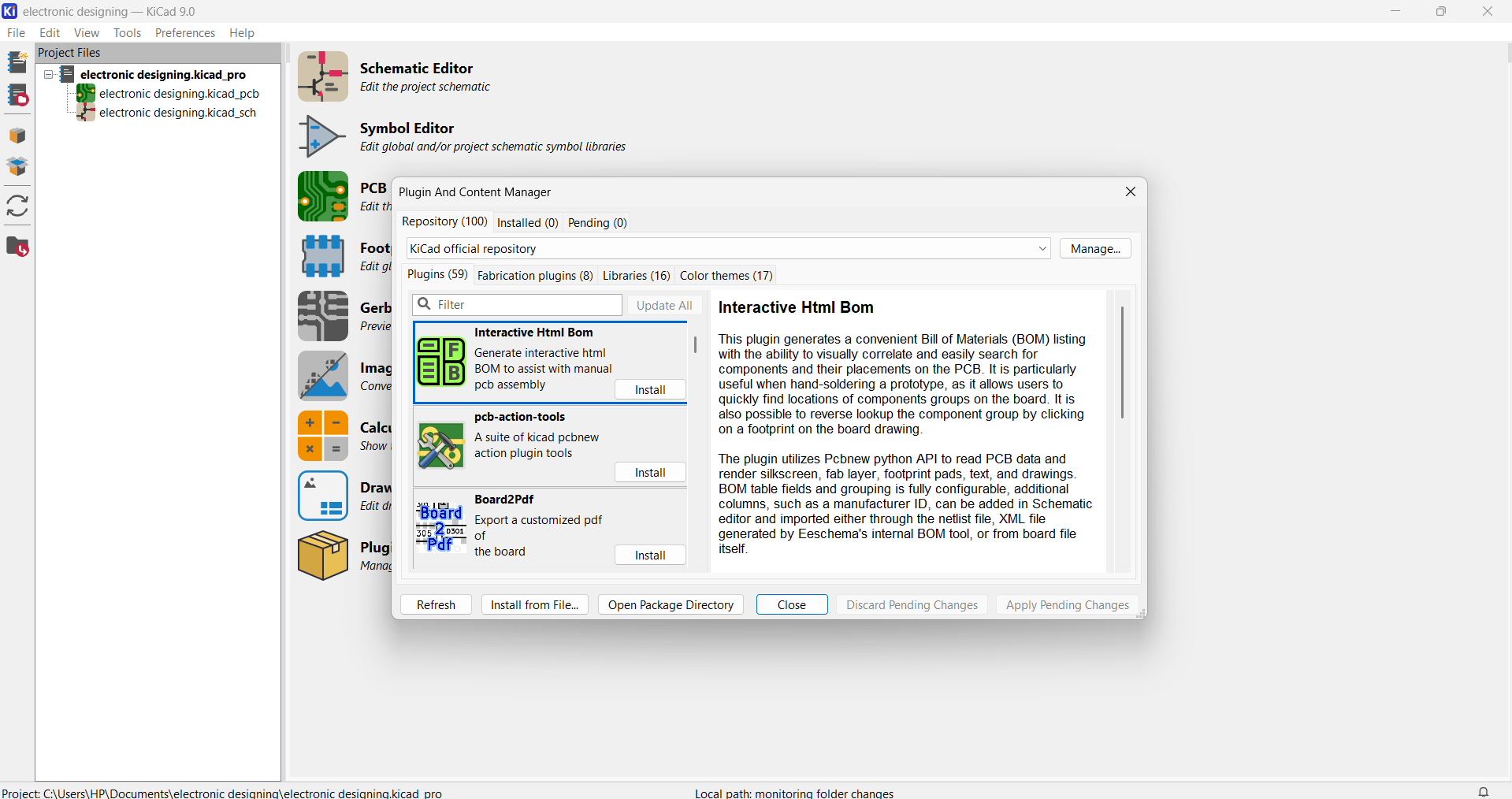
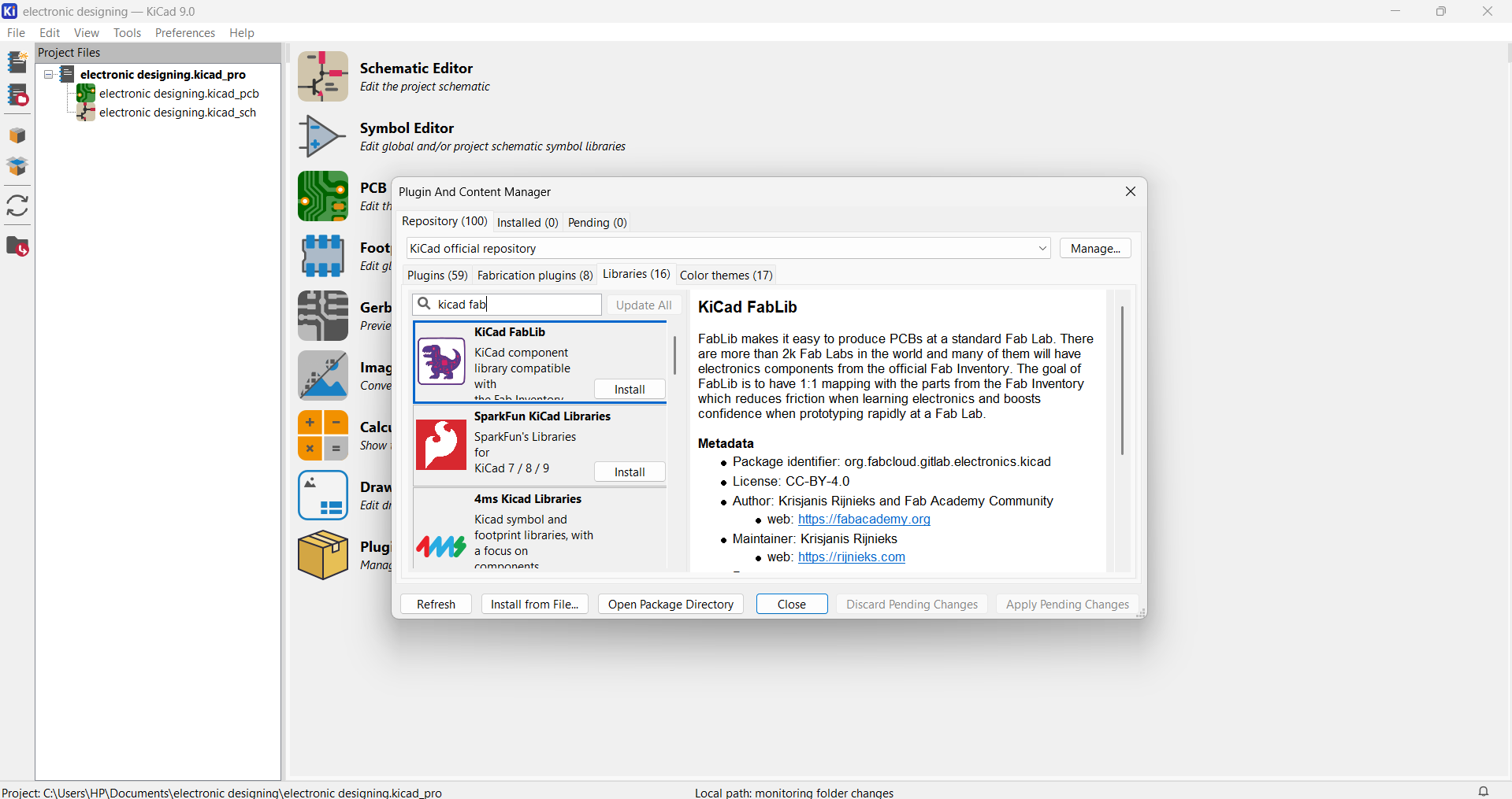
I installed the required component libraries in KiCad to ensure all necessary symbols and footprints were available for my PCB design Next, select plugin and content Manager and choose library for adding fab library
Choose fab KiCad library and click install
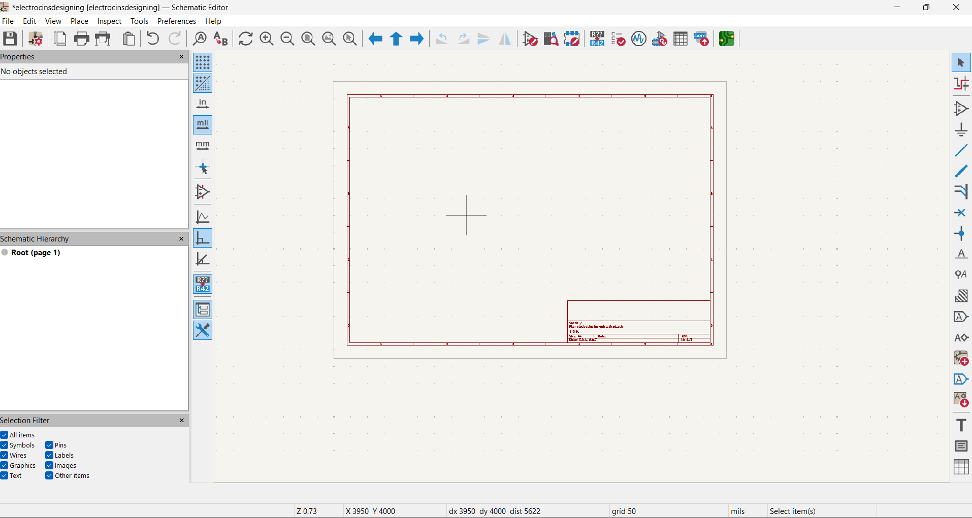
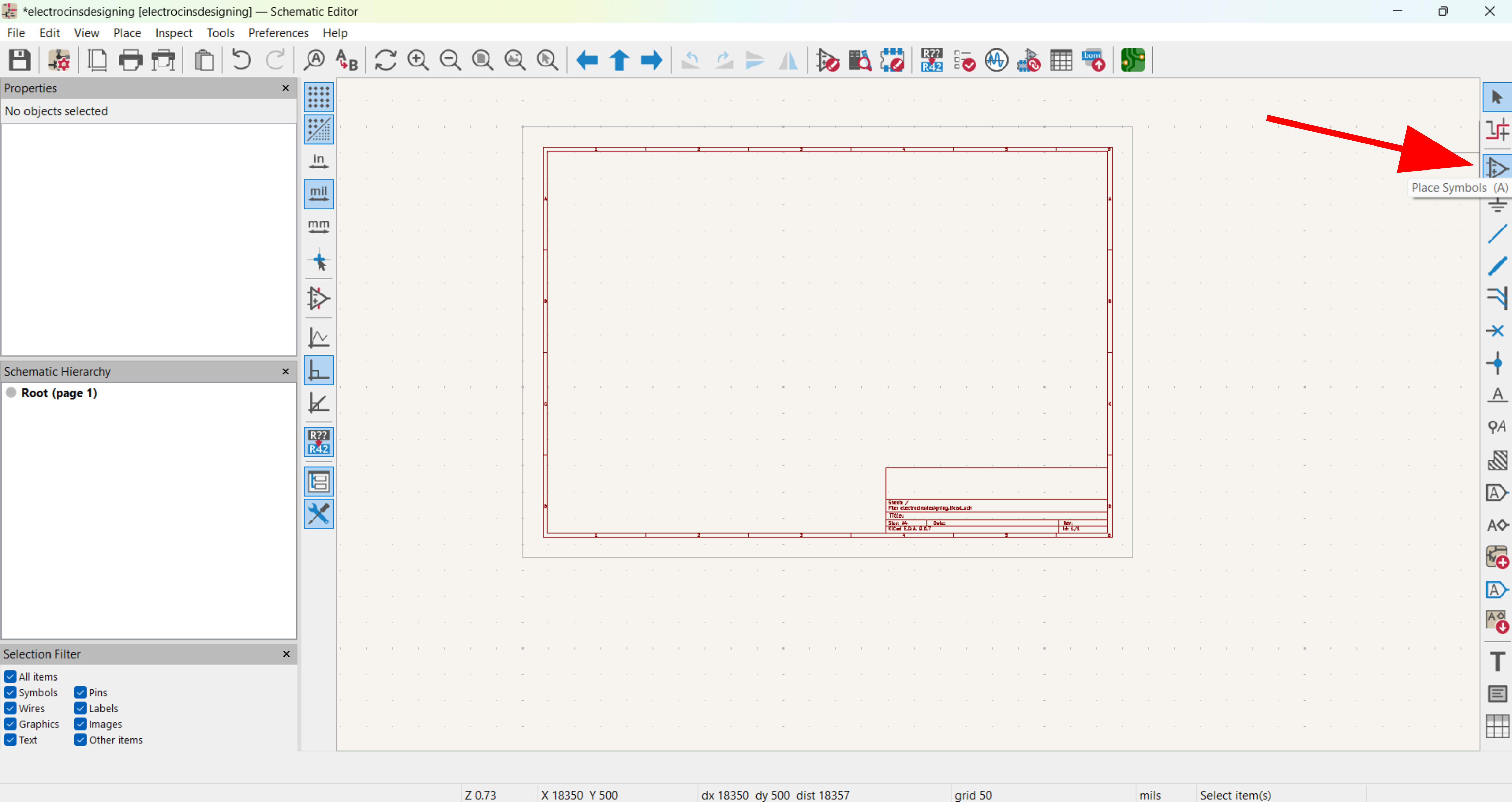
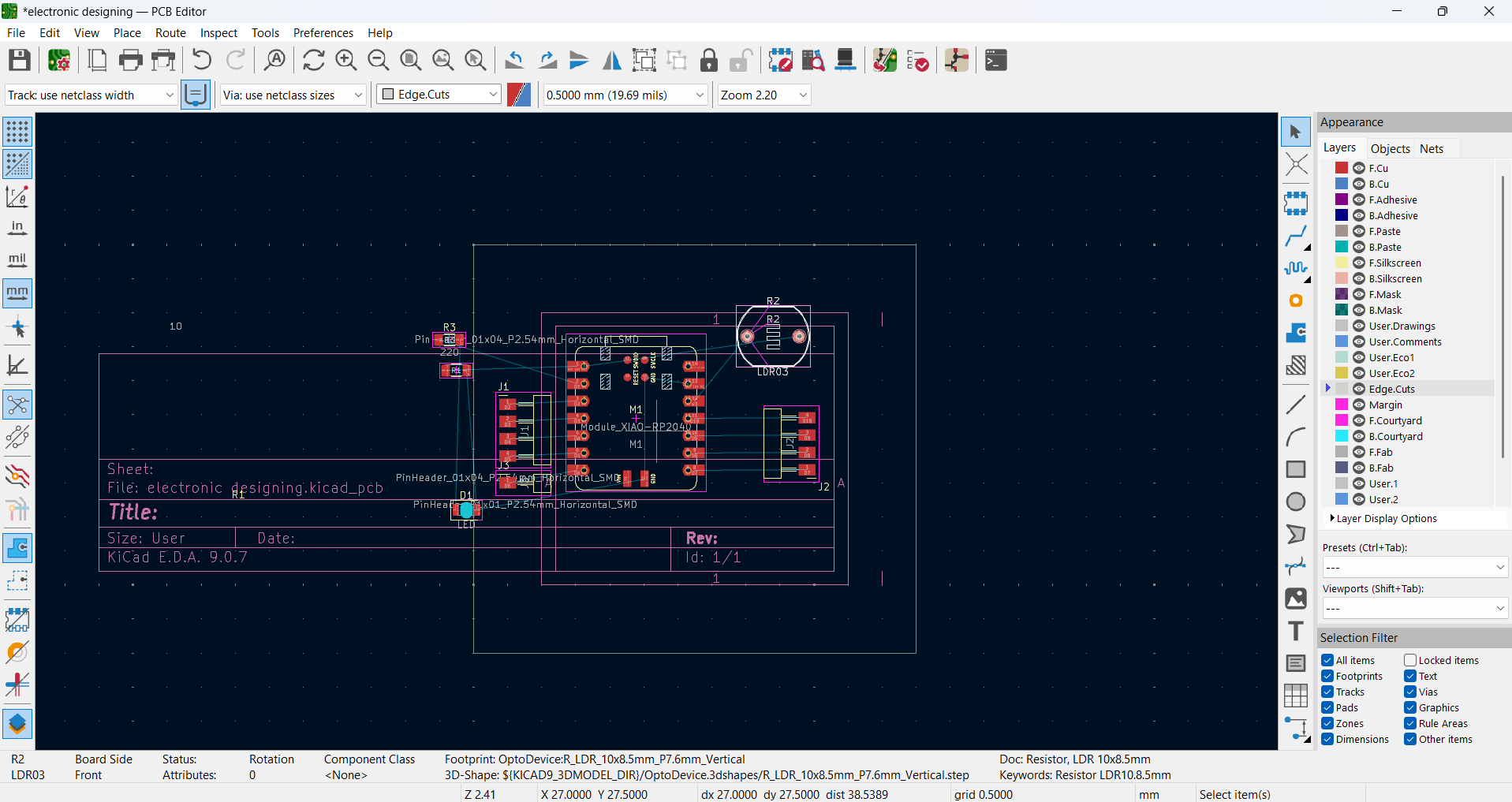
I opened KiCad and created a new project by selecting File → New Project, preparing the workspace for schematic
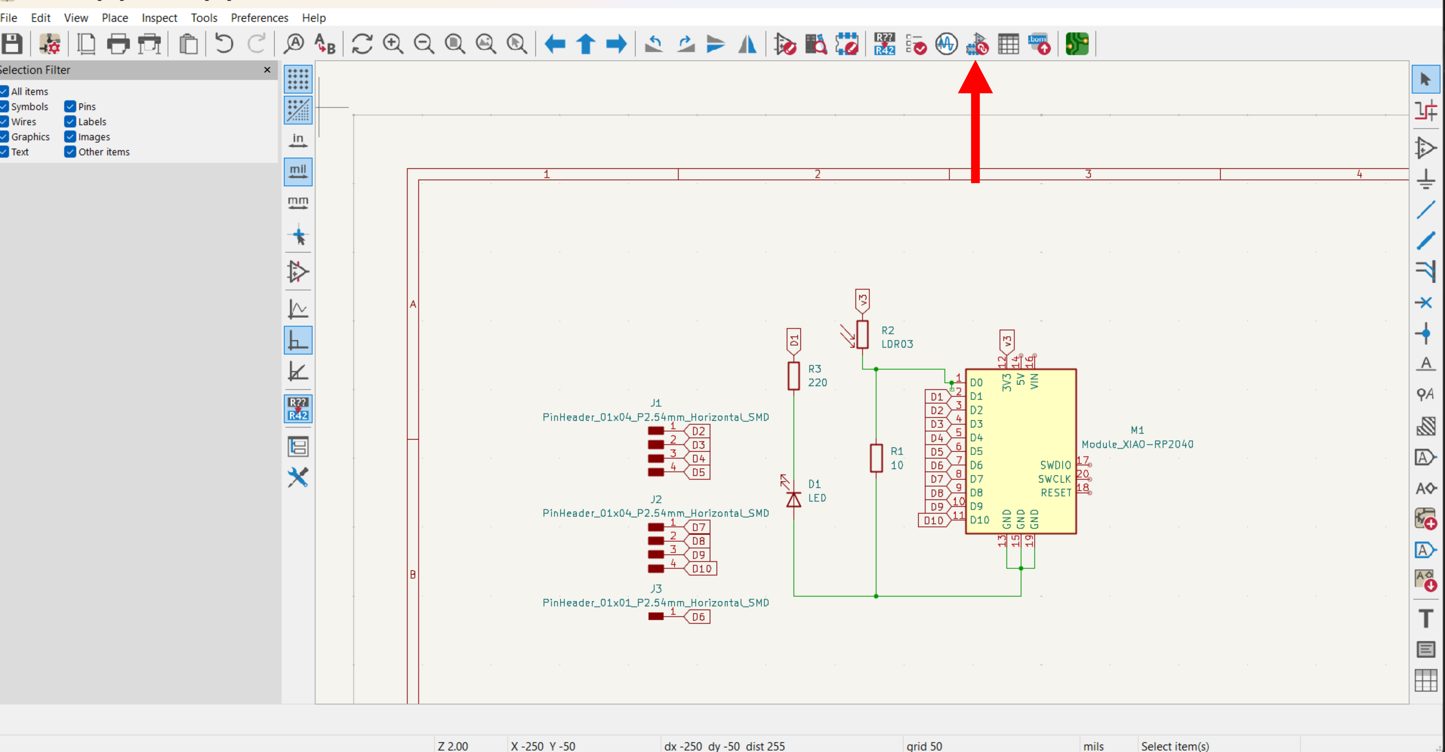
I opened the Schematic Editor and used the Symbol Tool to add the XIAO RP2040 microcontroller
Components Used
- XIAO RP2040 microcontroller
- LDR ( senses ambient light)
- 10 Ω resistor
- 220 Ω resistor
- LED 1206
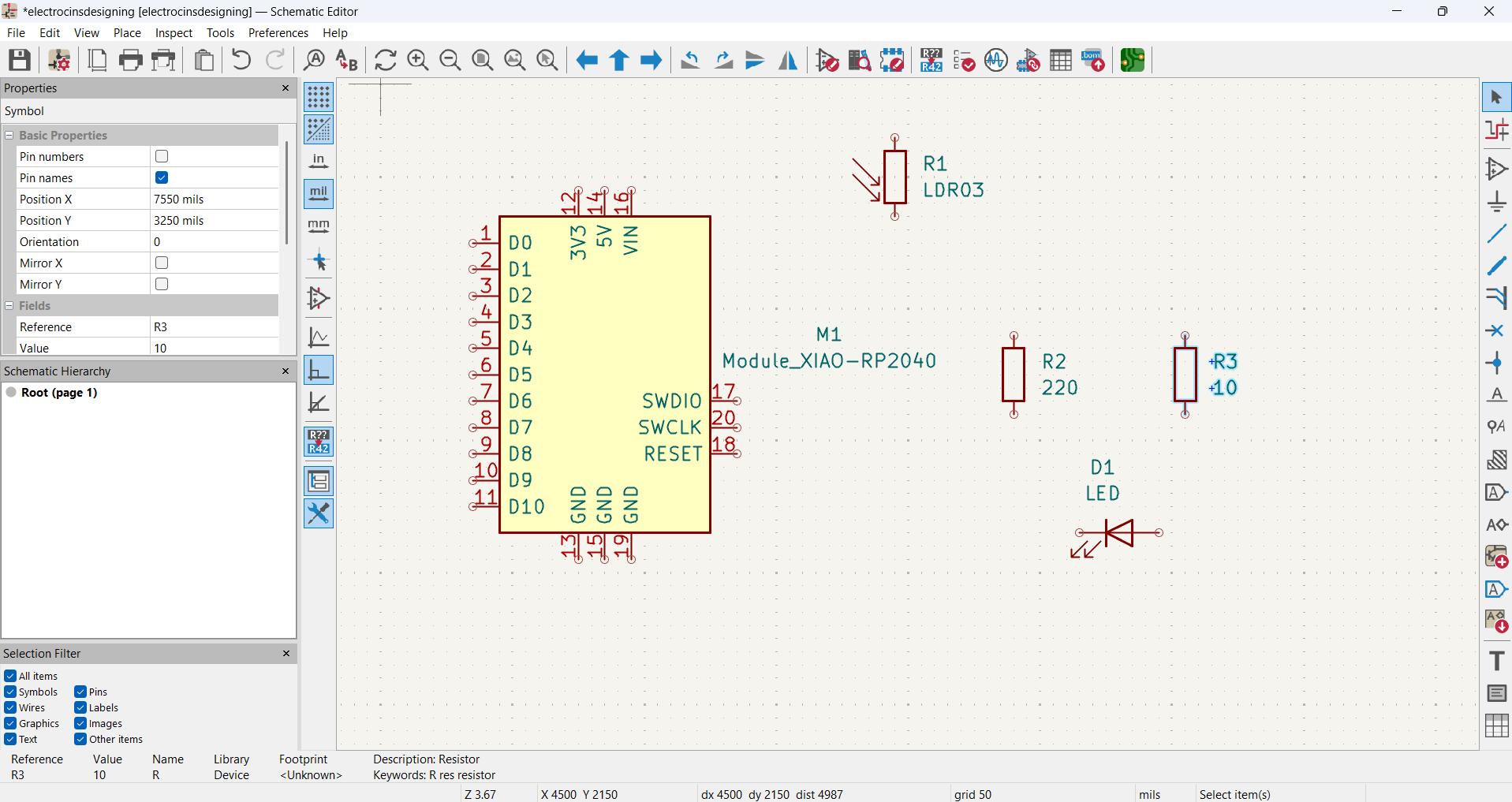
I started by opening the schematic editor in KiCad and adding the XIAO RP2040 microcontroller using this symbols
Next, I added the resistors from the component library and LDR ( senses ambient light)
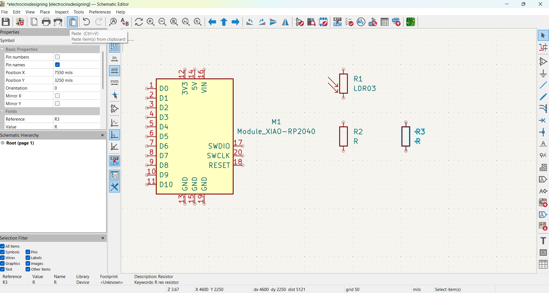
Next, I added the LED

Next, I updated the resistor values
Next, I connected all the components by wiring and Place Global Labels to keep the schematic clean the XIAO RP2040 pins, LDR, resistors, and LED according to the circuit schematic
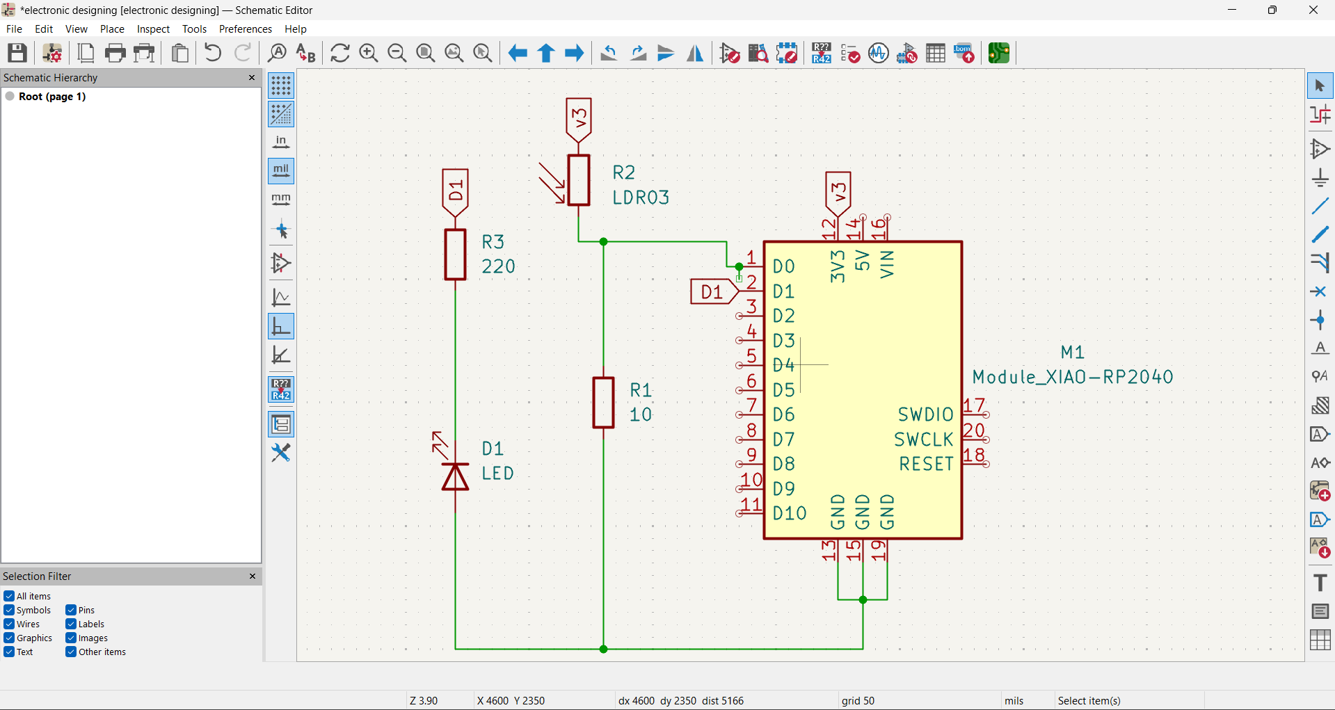
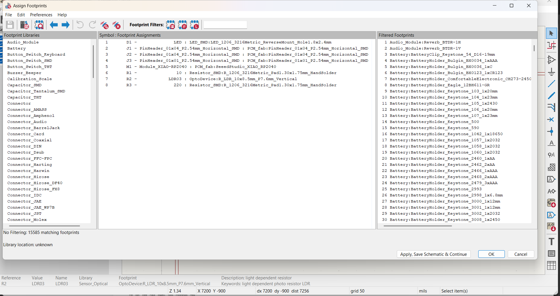
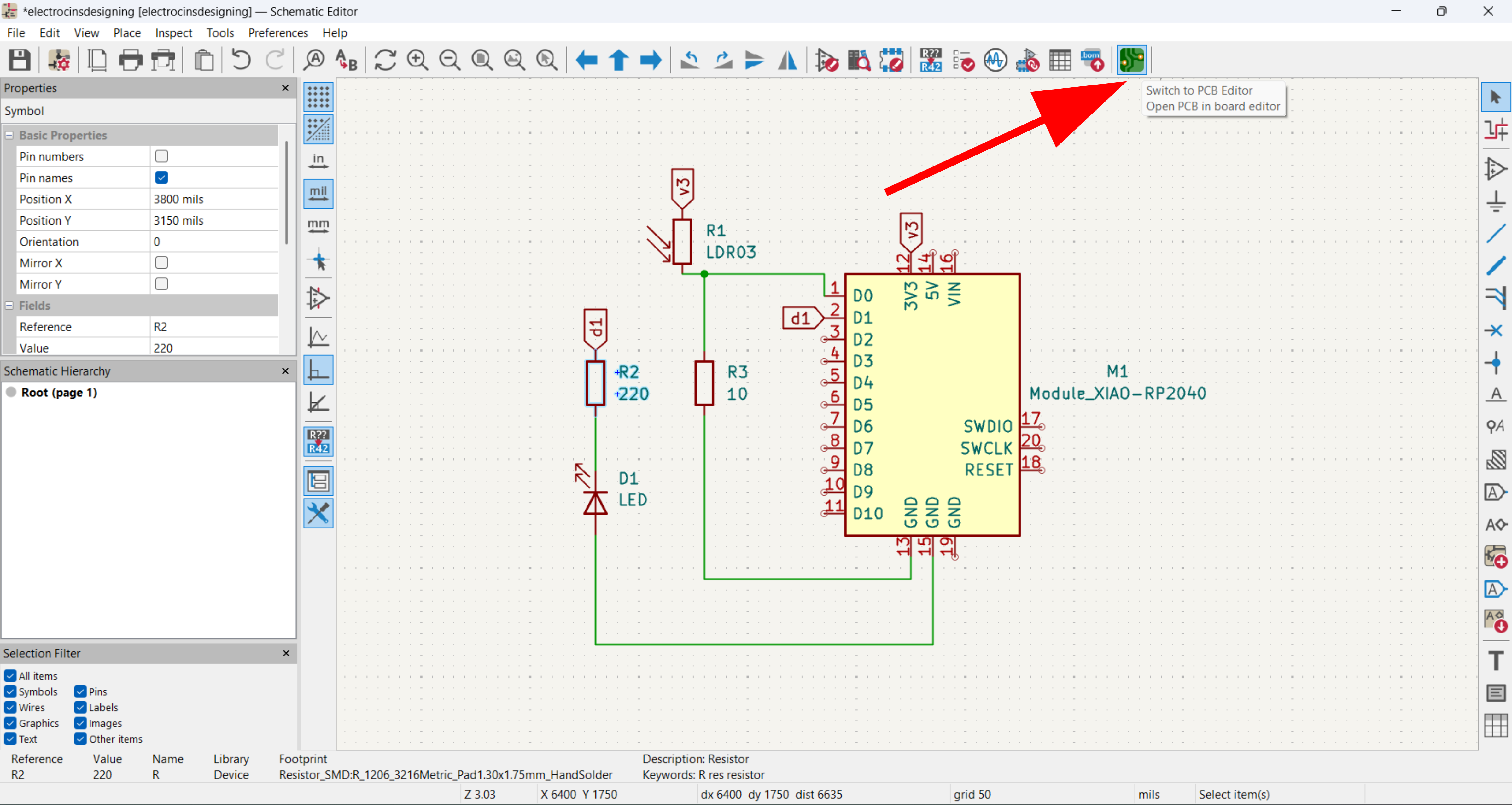
Next, I assigned footprints to verified that all connections were correct and All components were correctly connected
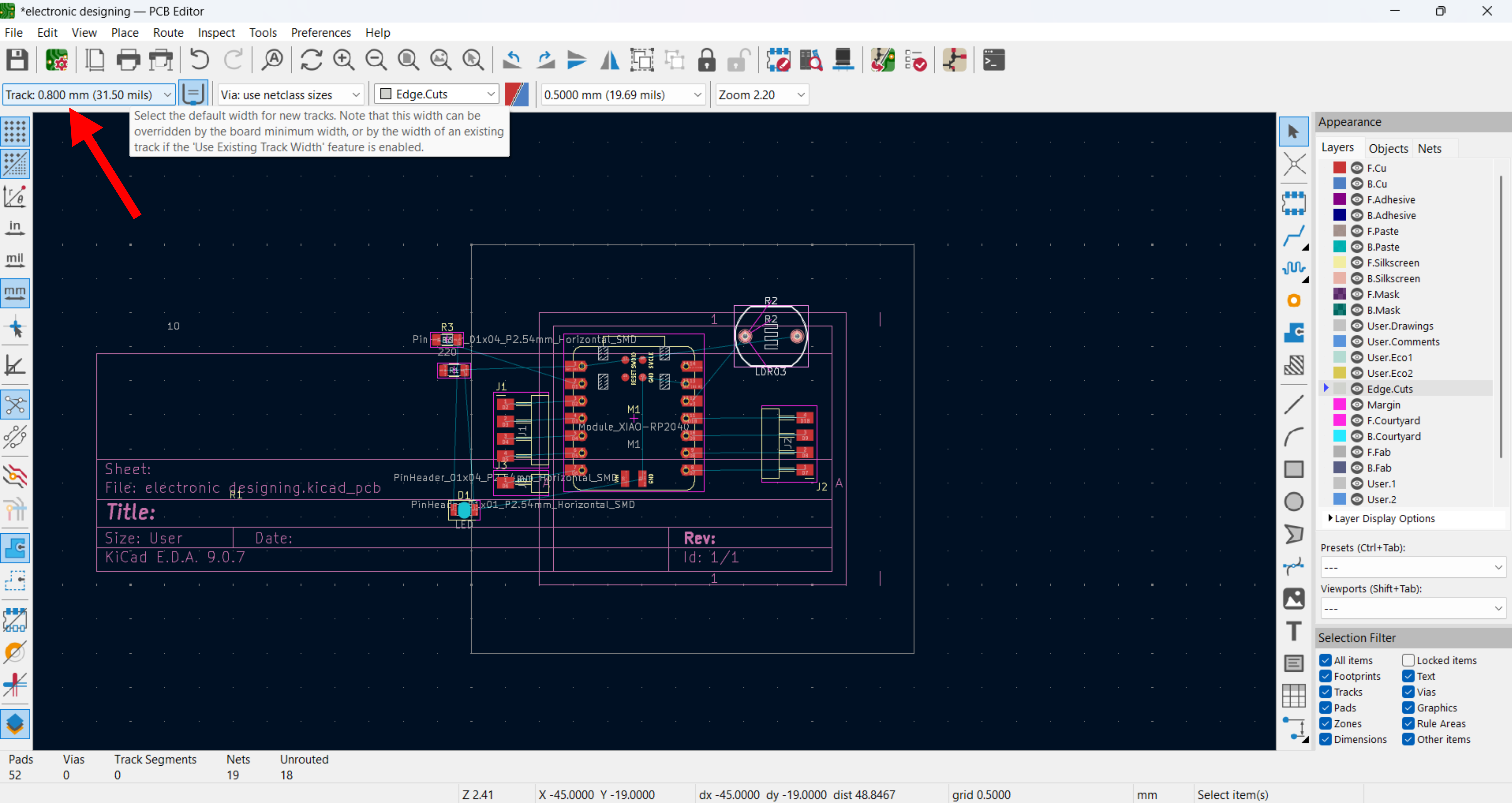
After assigning footprints, I switched to the PCB Editor
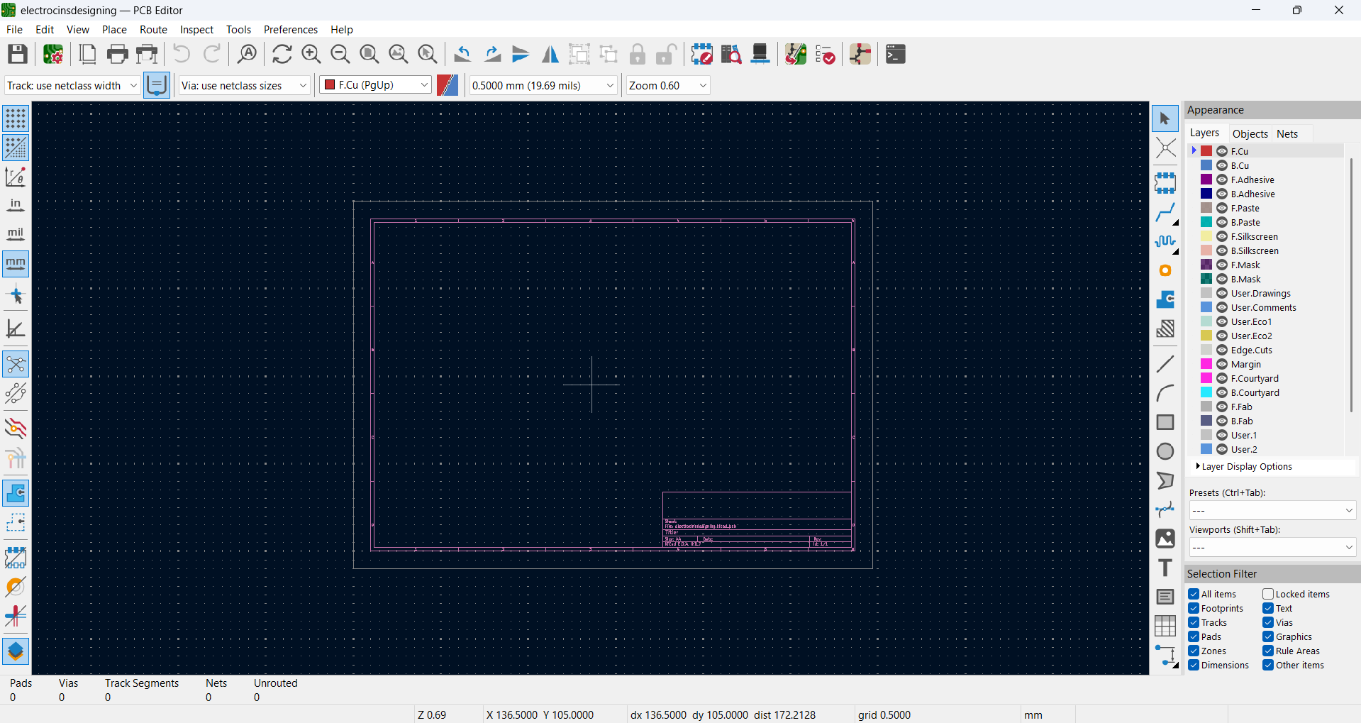
In the PCB Editor, I updated the board from the schematic and positioned all components in the editing area
For PCB routing, I set the track thickness to 0.8 mm
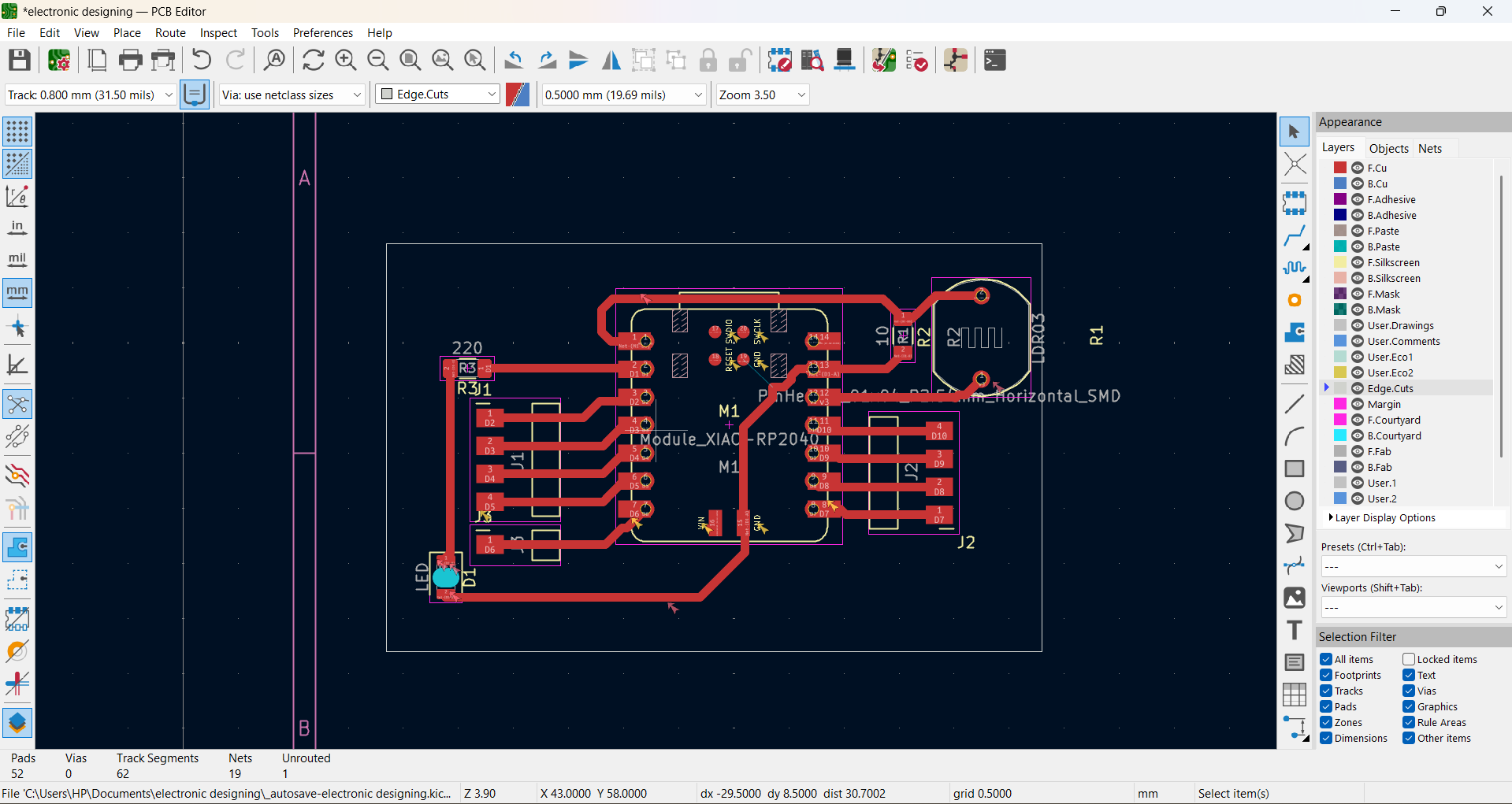
I routed the PCB carefully with 0.8 mm tracks, keeping the layout clean and minimizing crossovers.
and, completing the track routing, I added edge cuts to define the final shape and outline of the PCB
Hero shot
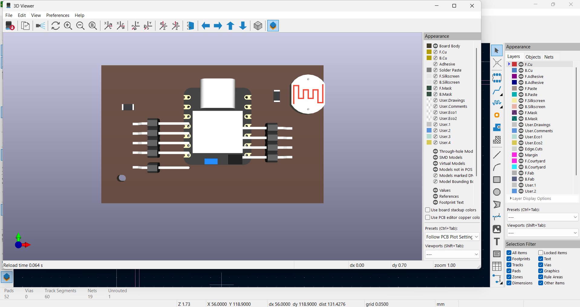
My finished smart light sensor board with the XIAO RP2040, LDR and LED