Assignment
Design and fabricatea a small 3D print a very small object (a few cubic centimeters in size, limited by printing time). The object must have a geometry that would be difficult or impossible to produce using subtractive manufacturing methods such as cutting, carving, or milling
Group Assignment
As a group we tested the design rules of our 3D printer. We printed test pieces to check the limits for overhangs, bridges, wall thickness and the clearance needed between moving parts. The full results are on our group page: group assignment page. What I learned is that steep overhangs need support and that very thin walls do not print cleanly, so I kept those limits in mind when I designed my object.
For my object I designed a cube with a pipe running through the inside of it. An enclosed channel like that cannot be reached by a cutting or milling tool, so it has to be made by 3D printing. That is exactly why it cannot be made subtractively.
3D PRINTING
Design
Begin by opening SolidWorks, and select Part to create a new part file for the design
.png)
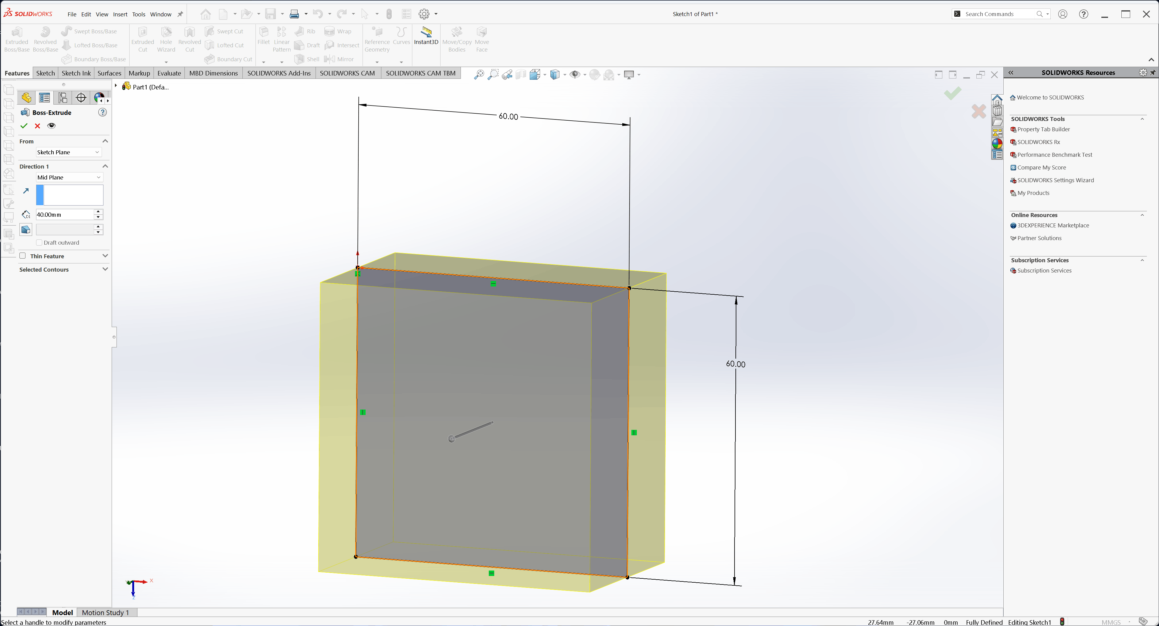
I selected the Front Plane as the reference plane for the initial sketch, drew a square to define the base of the cube, and then used the Extrude feature to create the 3D shape
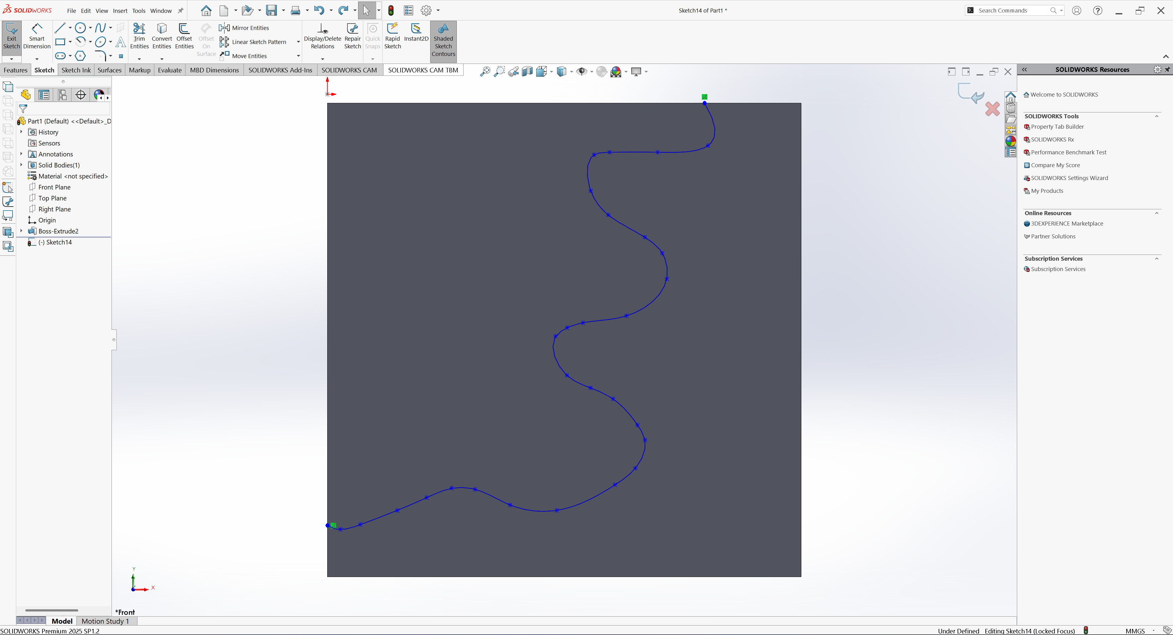
After creating the cube, I created the new sketch on the same Front Plane that was used to sketch the cube line that would serve as the center path for the pipe passing through the cube
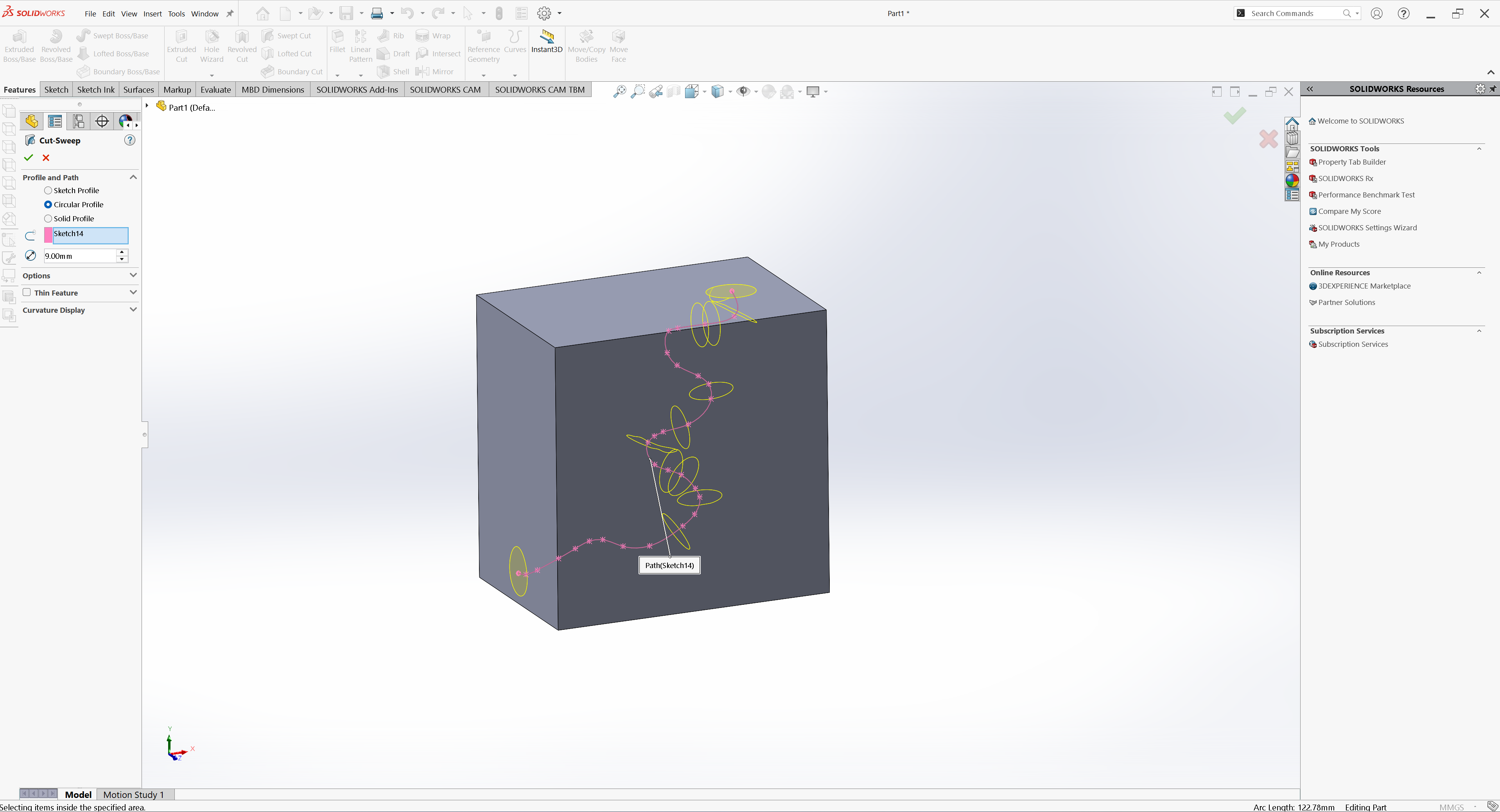
Next, I navigated to the Features tab and selected Swept Cut to remove material along the previously defined path, forming the hollow pipe inside the cub
The Swept Cut successfully removed material along the defined path
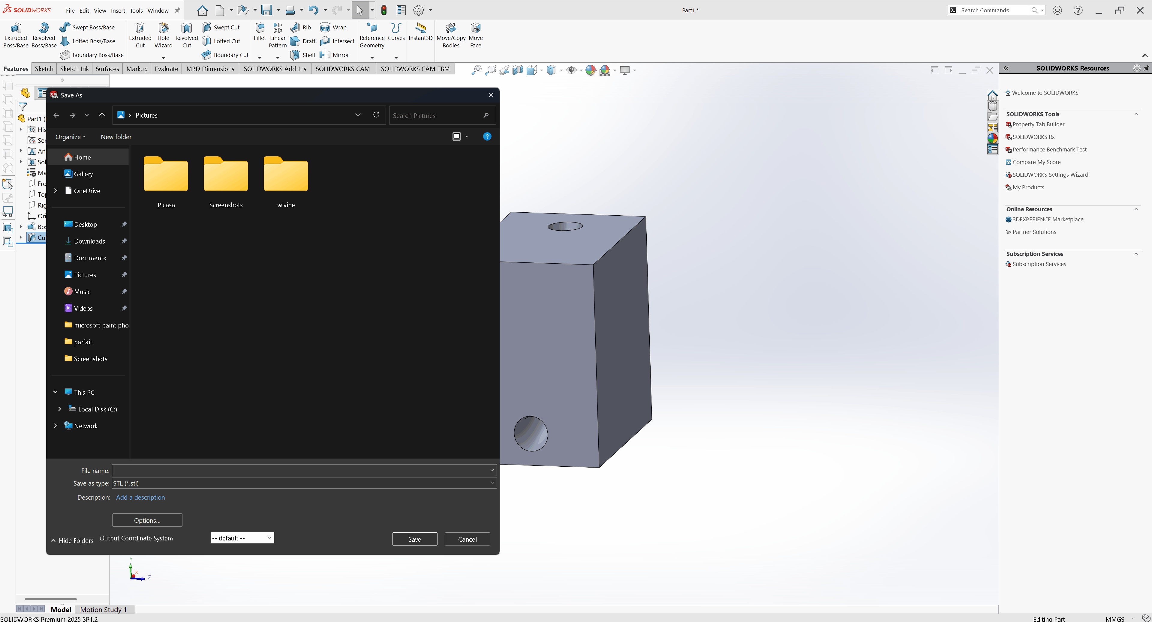
After completing the design, I saved the model as an STL file to prepare it for slicing and 3D printing
After saving the model as an STL file, I launched Creality Slicer and imported the design.
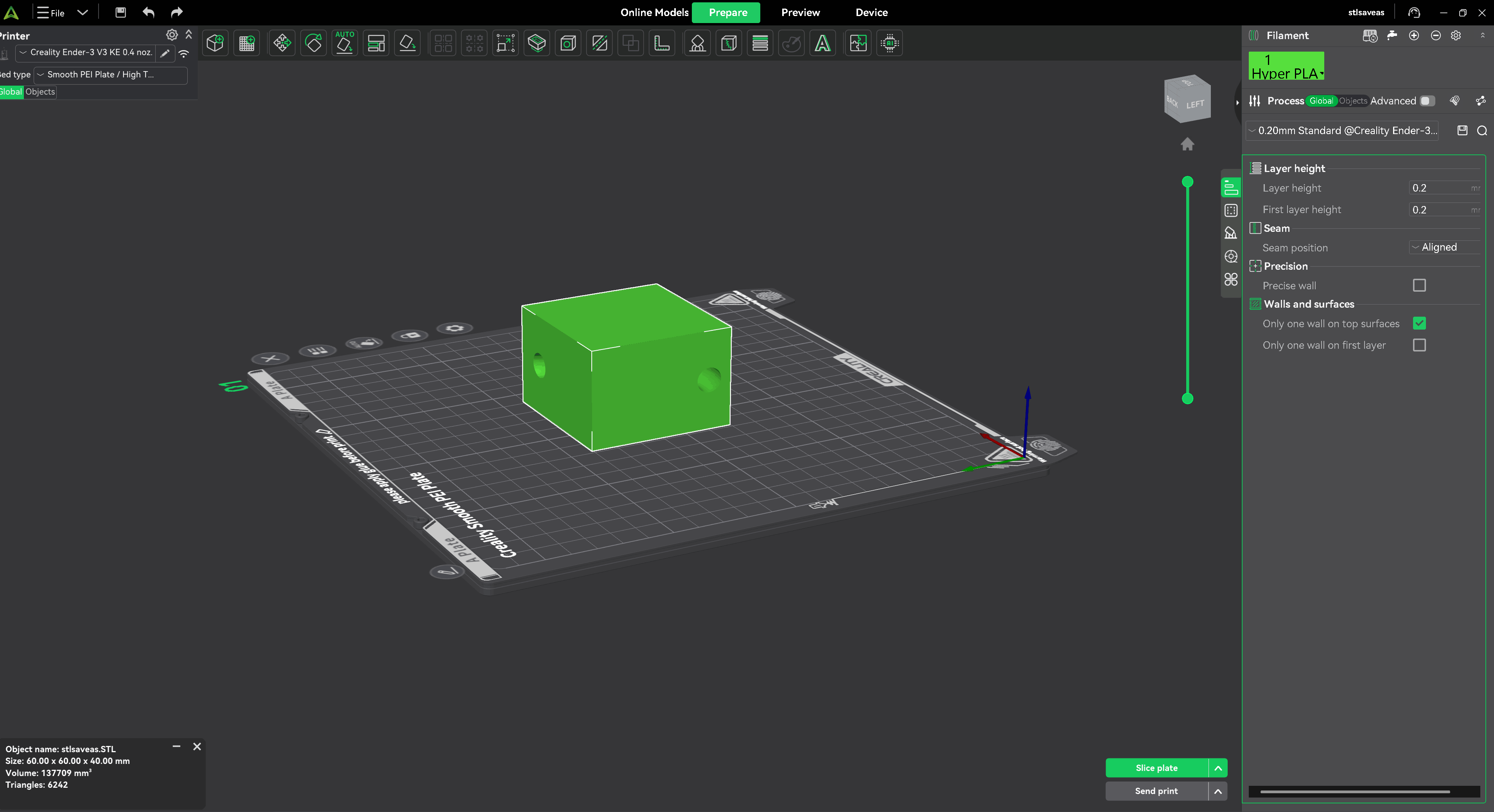
After, I set the infill density to 15% to balance material usage with structural strength
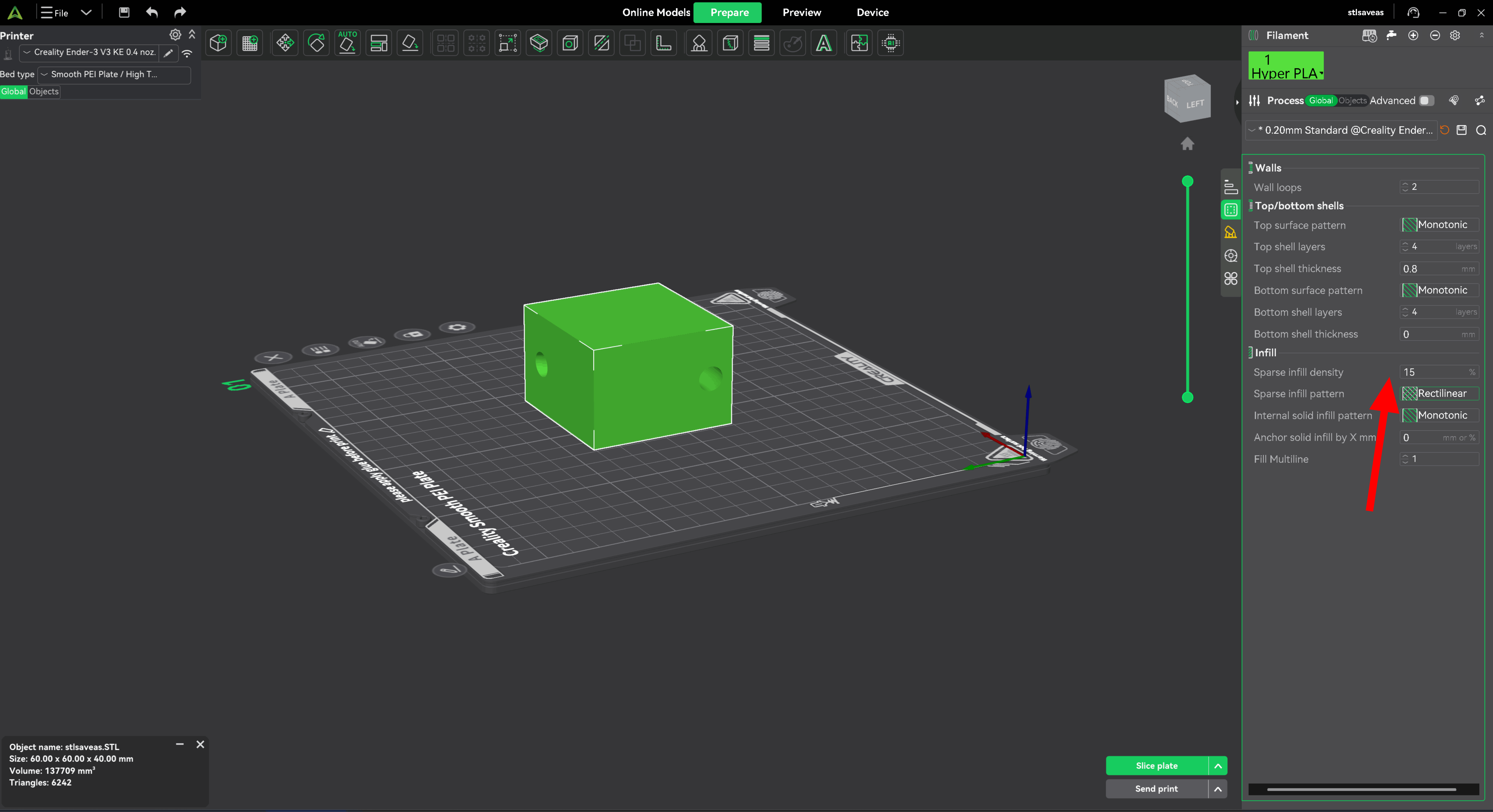
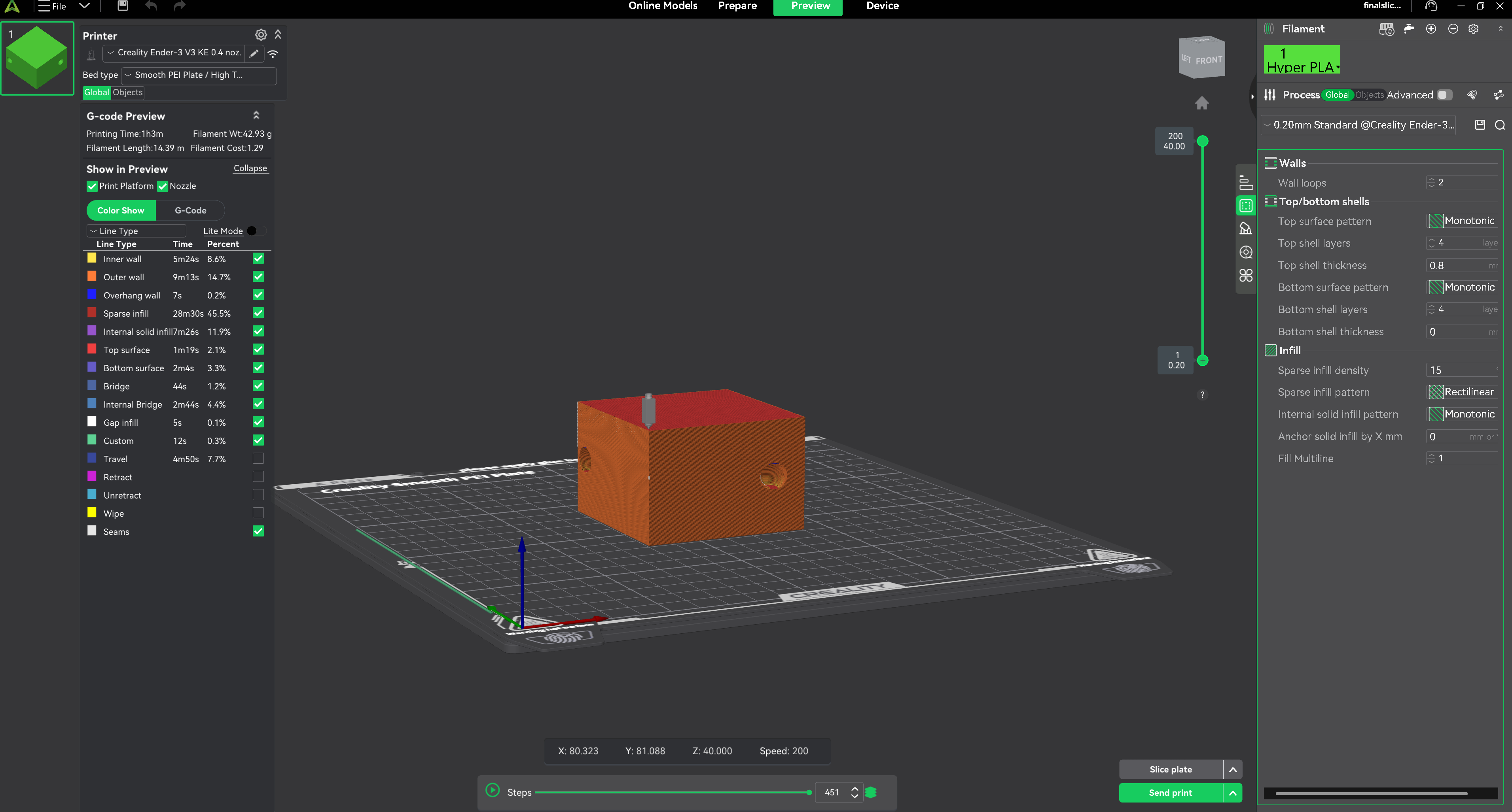
After setting the infill to 15%, I clicked the Slice in Creality Slicer to generate
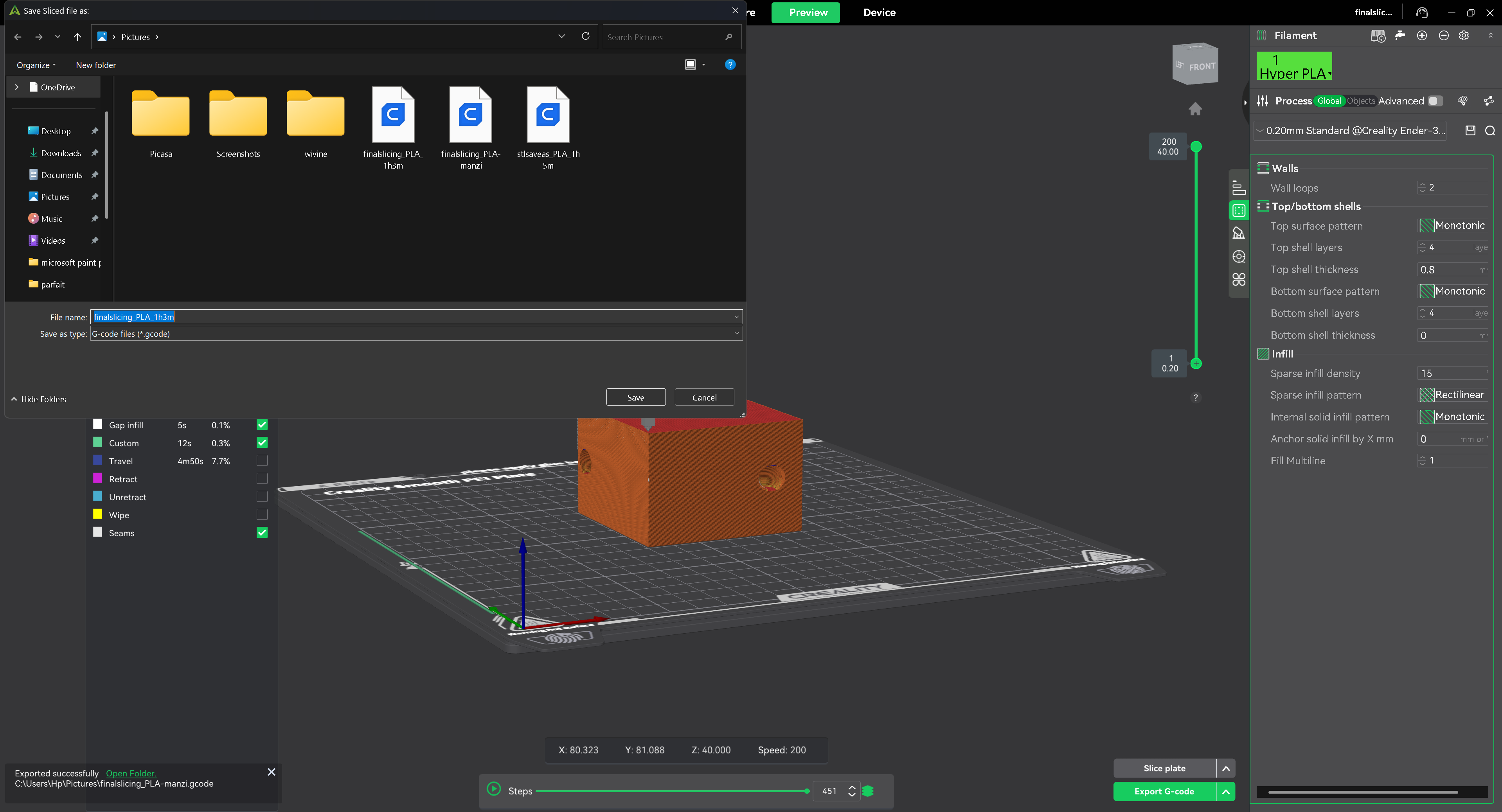
the slicing process was complete, I exported the sliced model by selecting “Save as G-code” in Creality Slicer. This file contains all the instructions needed for the 3D printer, including movements, speeds, and extrusion settings
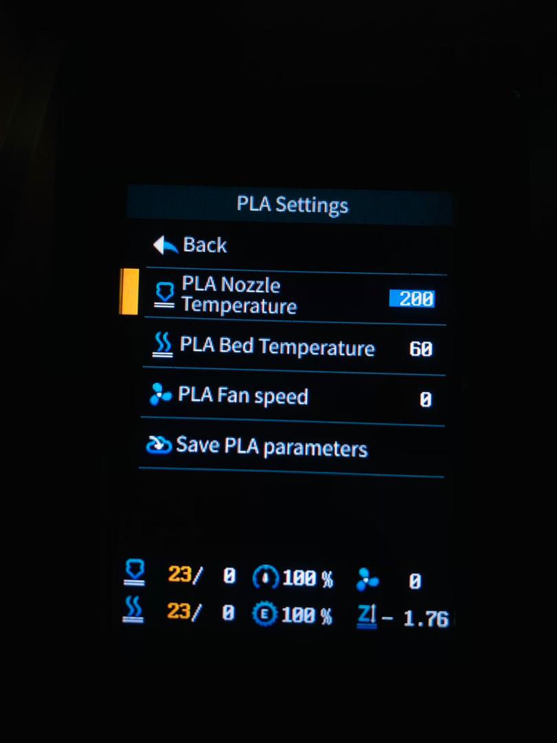
I moved to the Creality v3 SE and turned it on. I inserted the removable disk containing the sliced file. First, I checked the printer leveling and confirmed it was correct. Then, I heated the nozzle to test the filament flow
The PLA nozzle temperature was set to 200 °C. because it is the ideal melting temperature for most PLA filament.that why i choosed 200 °C.
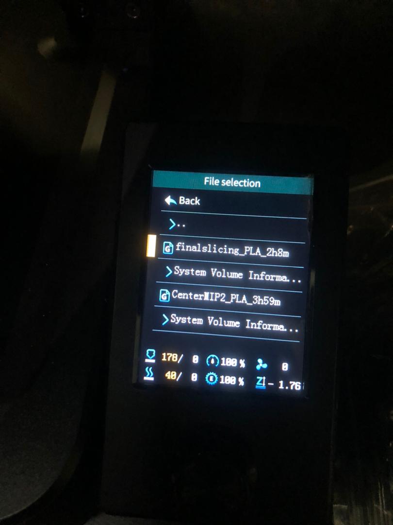
After that, I selected my file from the disk
started printing.
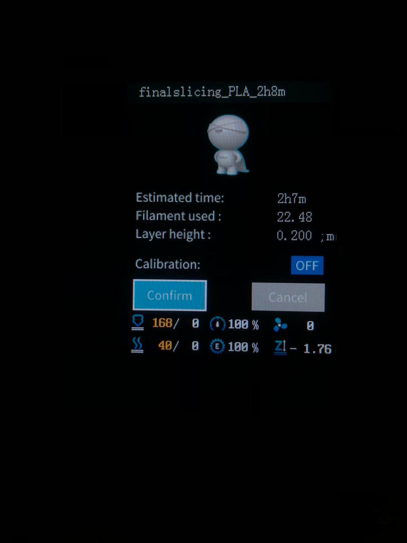
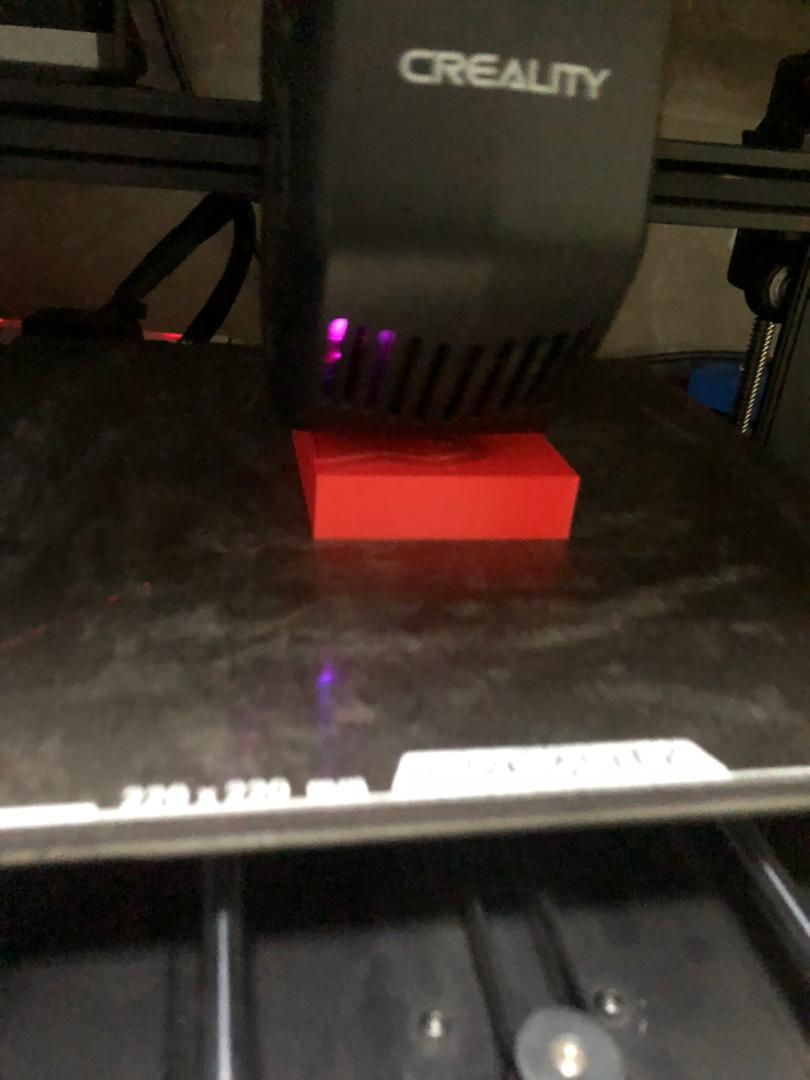
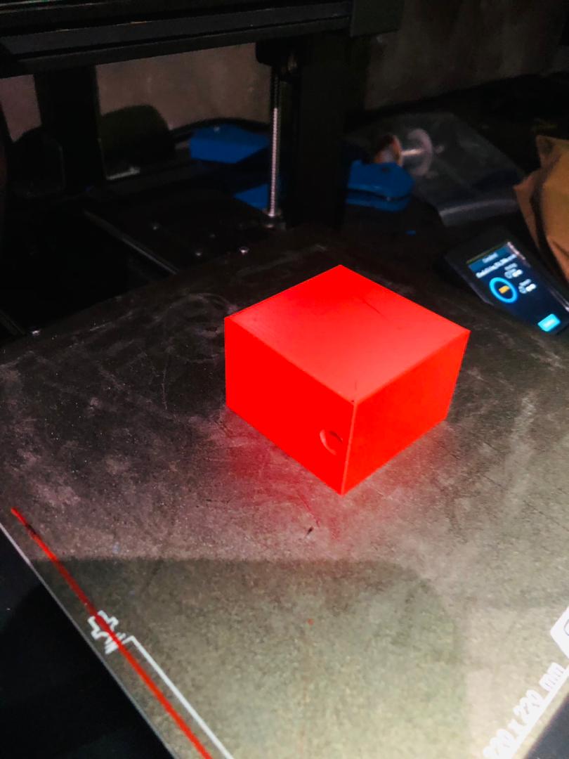
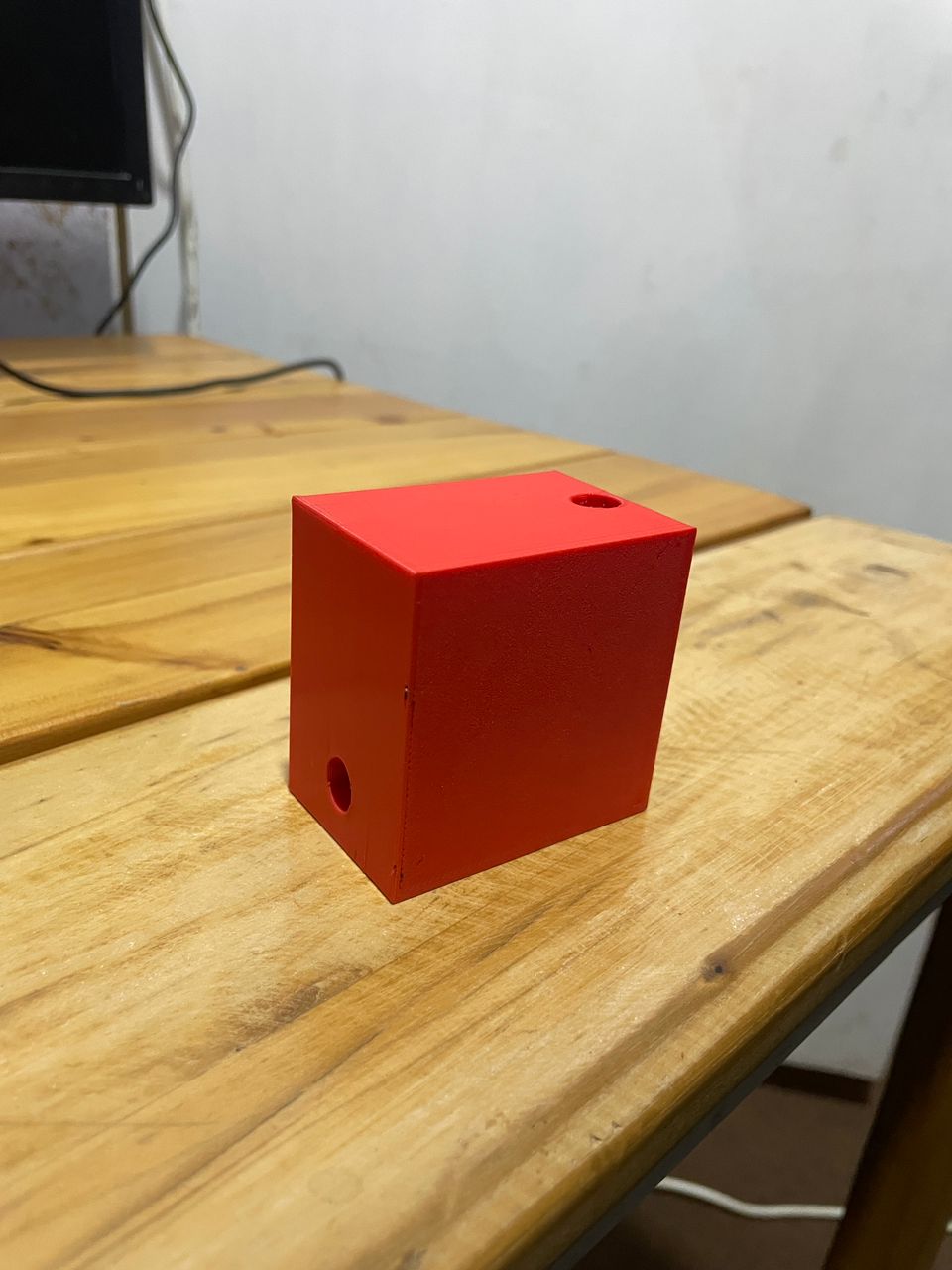
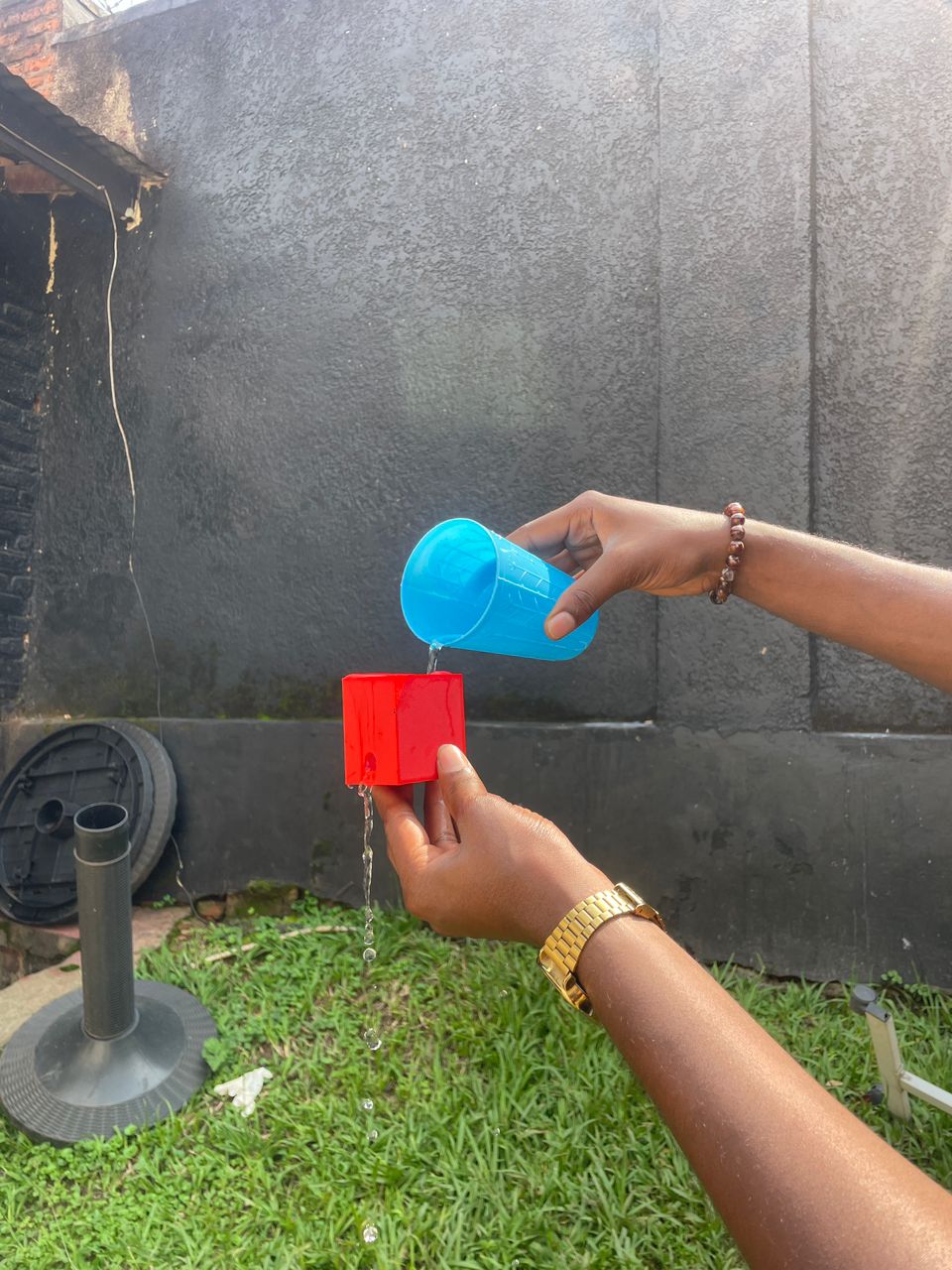
printing file
slicing file3D Scanning
3D scanning is a technology that captures the exact shape, size, and surface details of a real object and converts them into a digital 3D model.. It uses lasers, light, or cameras to measure the surface of the object
I scanned a woodfix bottle using my smartphone with an application called Kiri Engine. It is a mobile application that allows you to create a 3D model of a real object using your phone camera
These are the steps I followed in Kiri Engine:
- I placed the woodfix bottle on a table with even light and slowly took photos all the way around it, keeping the whole bottle in every shot.
- I moved around the bottle at a low, a middle and a high angle so the camera captured the top, the sides and the base.
- I uploaded the photos in Kiri Engine and let it process them into a 3D model in its cloud.
- When it finished I checked the model, cleaned the stray points, and exported it as a mesh file.
Capturing the woodfix bottle from all sides with Kiri Engine on my phone
The finished 3D scan of the bottle in Kiri Engine