Assignment
Group assignment: demonstrate and compare the toolchains and development workflows for the embedded architectures we have, and document what we learned.
Individual assignment: browse the datasheet of a microcontroller, then write and test a program for an embedded system that interacts with local input or output devices.
Group Assignment: comparing toolchains
As a group we compared the main ways to write and flash firmware for our boards. We looked at the Arduino IDE, which is the simplest to start with and hides the build system, ESP-IDF, which is Espressif's own framework in C with full control but a steeper learning curve, and PlatformIO inside VS Code, which sits in the middle and keeps the project settings in one file. The full write up is on our group page: group assignment page. For this week I used the Arduino IDE because it is the fastest way to get a first program running.
Browsing the microcontroller datasheet
Before writing any code I browsed the ESP32 datasheet to learn the parts that matter when programming. The points I used are that the chip works at 3.3 V (so a 5 V signal can damage a pin), it has a 12 bit ADC for reading analog sensors, many GPIO pins that I set with pinMode and digitalWrite, and it supports I2C, SPI and UART for talking to other devices. Knowing the GPIO numbers from the datasheet is how I picked pins 23, 22 and 21 for my three LEDs.
Summary
This project demonstrates how to simulate a traffic light system using ESP32 in Wokwi. The system controls three LEDs (Red, Yellow, and Green) to operate like a real traffic light using programmed time delays
The ESP32 microcontroller combines strong processing capability with wireless connectivity features such as Wi-Fi and Bluetooth. Its efficiency and adaptability make it a popular choice for IoT and embedded development
Objectives
- To learn how to use ESP32 digital output pins
- To understand pinMode() and digital Write
- To simulate a real traffic light system
- To practice programming using Arduino IDE
Components Used
- ESP32 Dev Module
- 3 LEDs (Red, Yellow, Green)
- 3 Resistors (220Ω)
Simulation Outcome
The simulation successfully demonstrated a working traffic light system. The green LED stayed on for 5 seconds, followed by yellow for 2 seconds, and red for 5 seconds. The sequence repeated continuously.
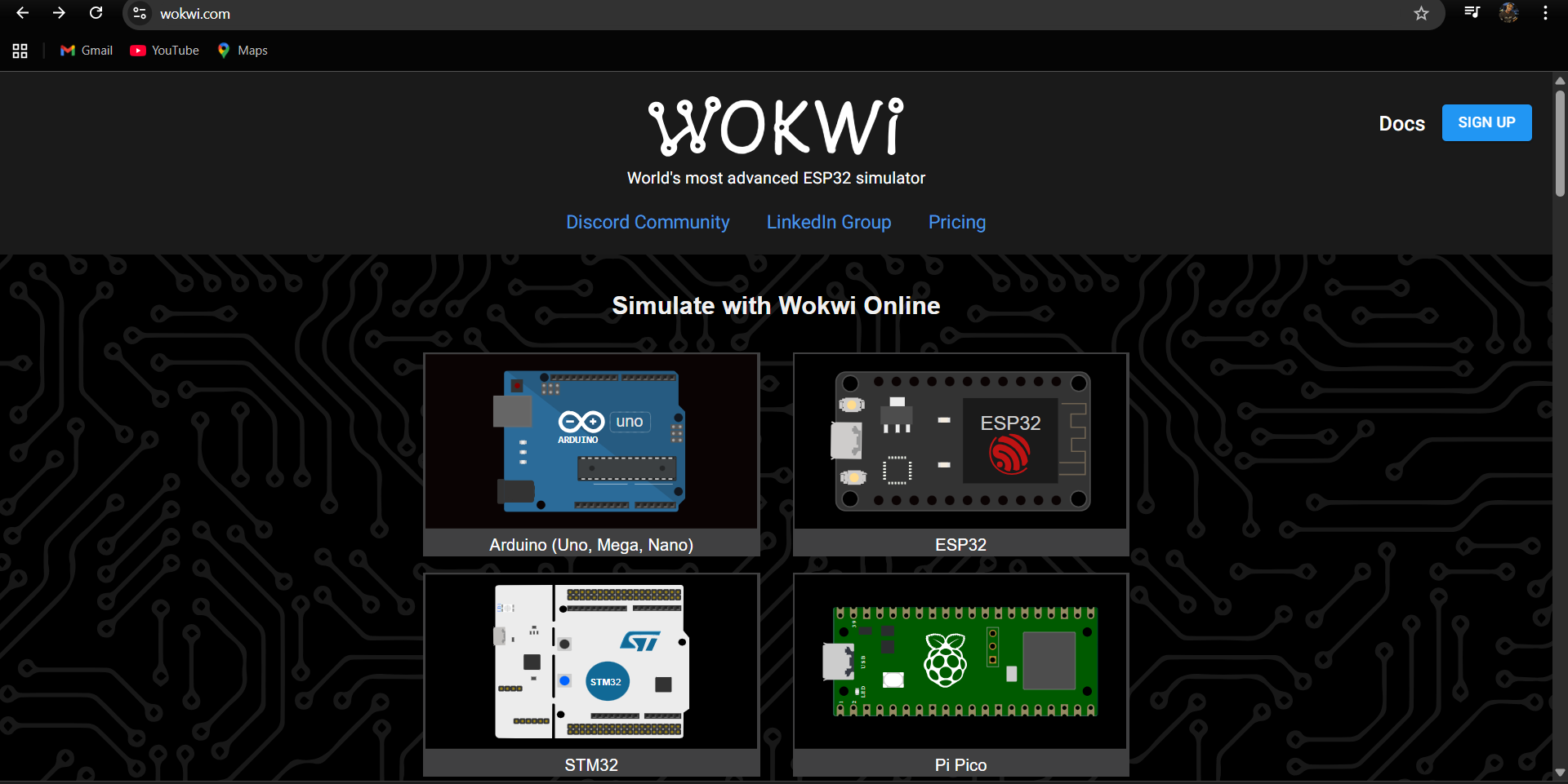
After that, I opened Wokwi
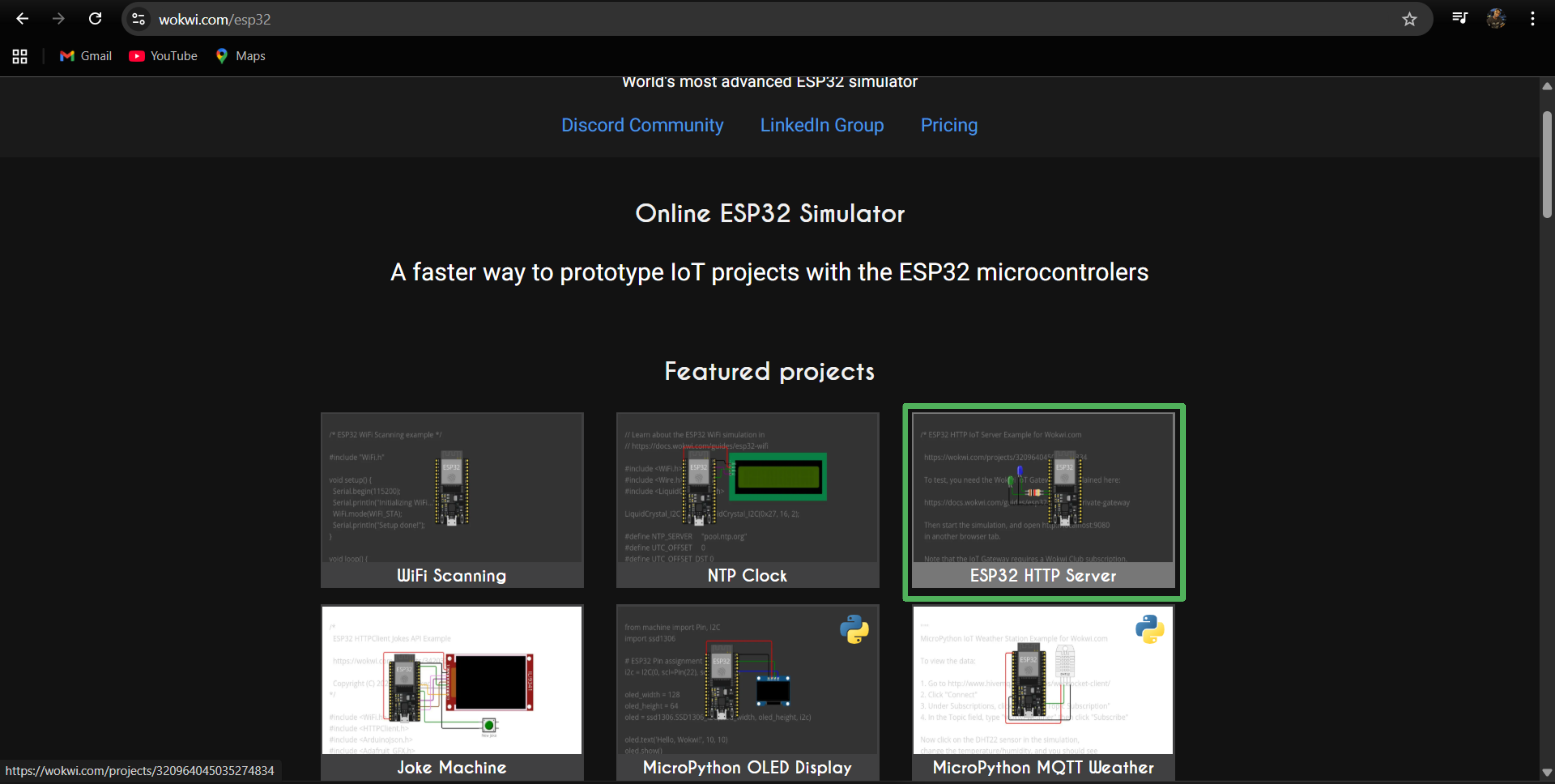
After selecting the ESP32 board
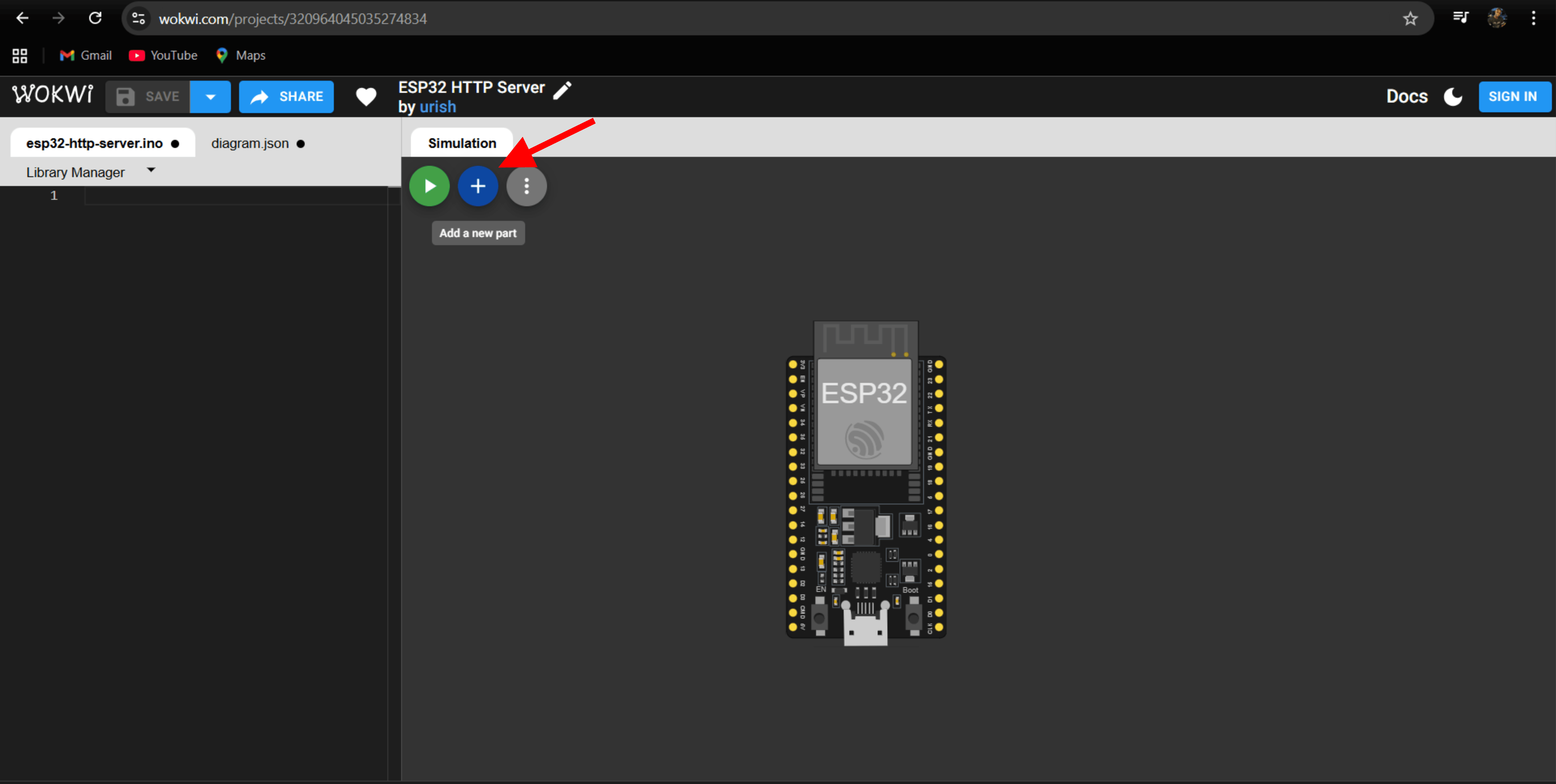
After opening the ESP32, I started adding the required components like LEDs and resistors
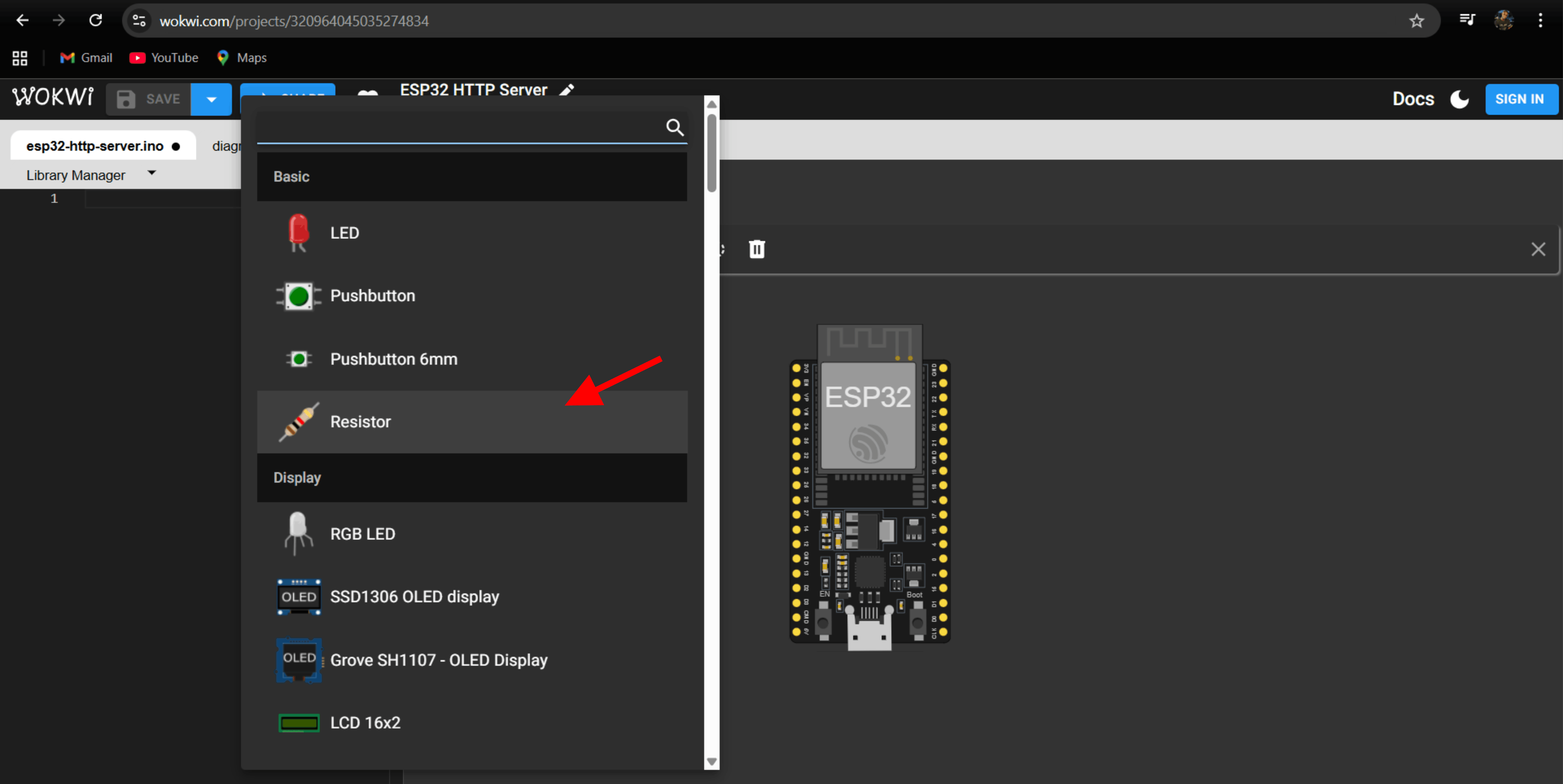
next, adding the resistors
After that, I added the red LED
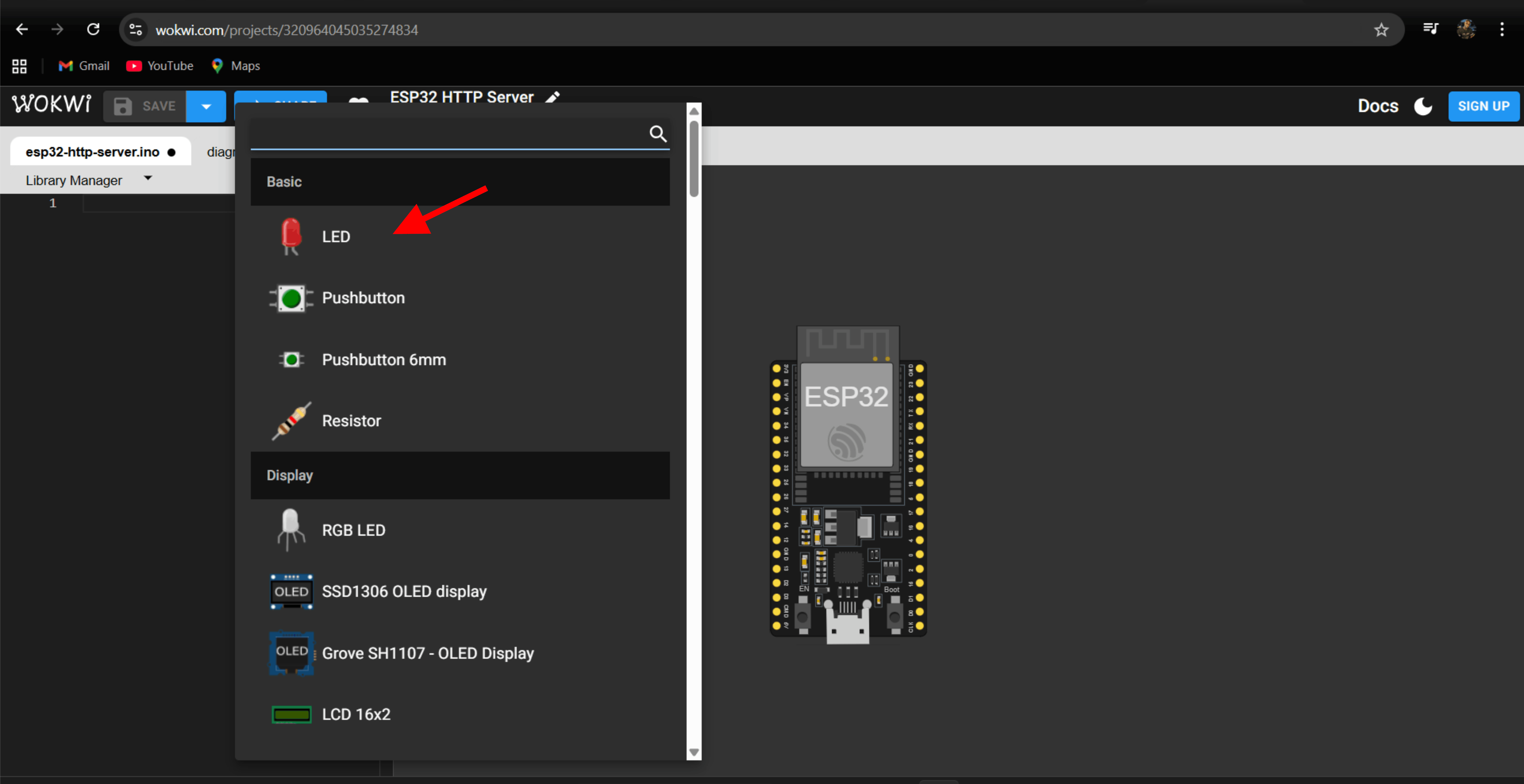
Then, I changed the resistor value to 220 ohms to control the current flowing to the LED
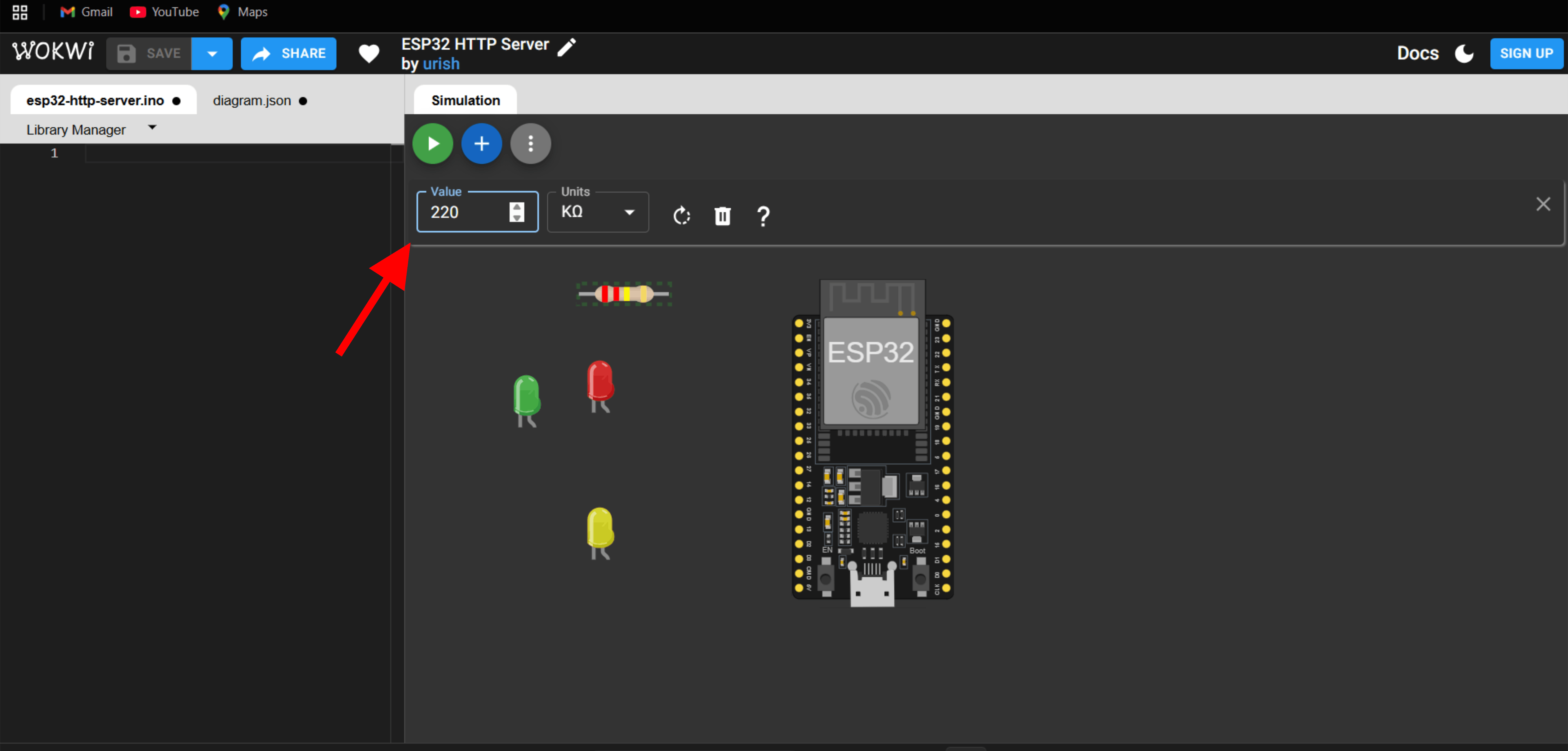
After all the components were ready
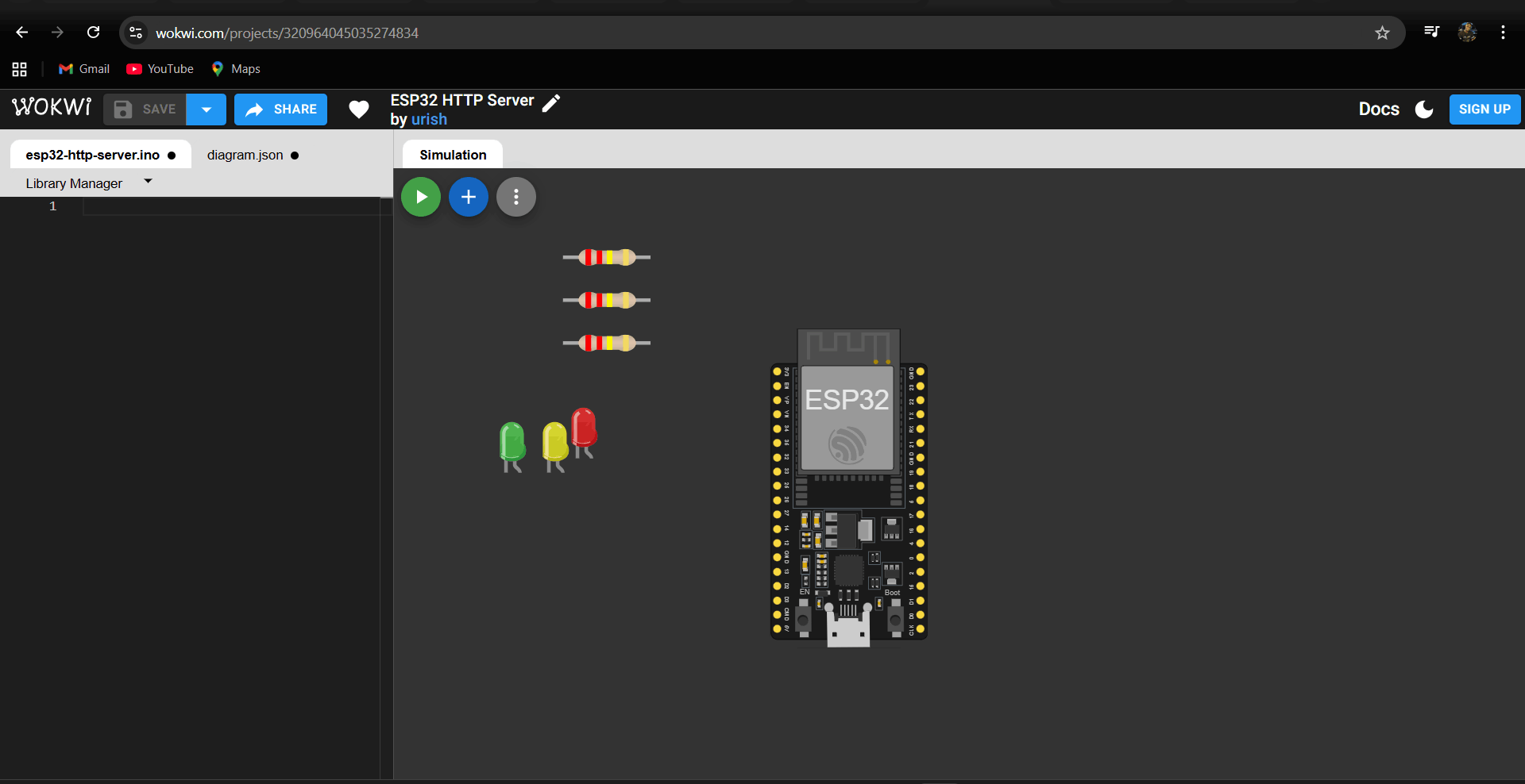
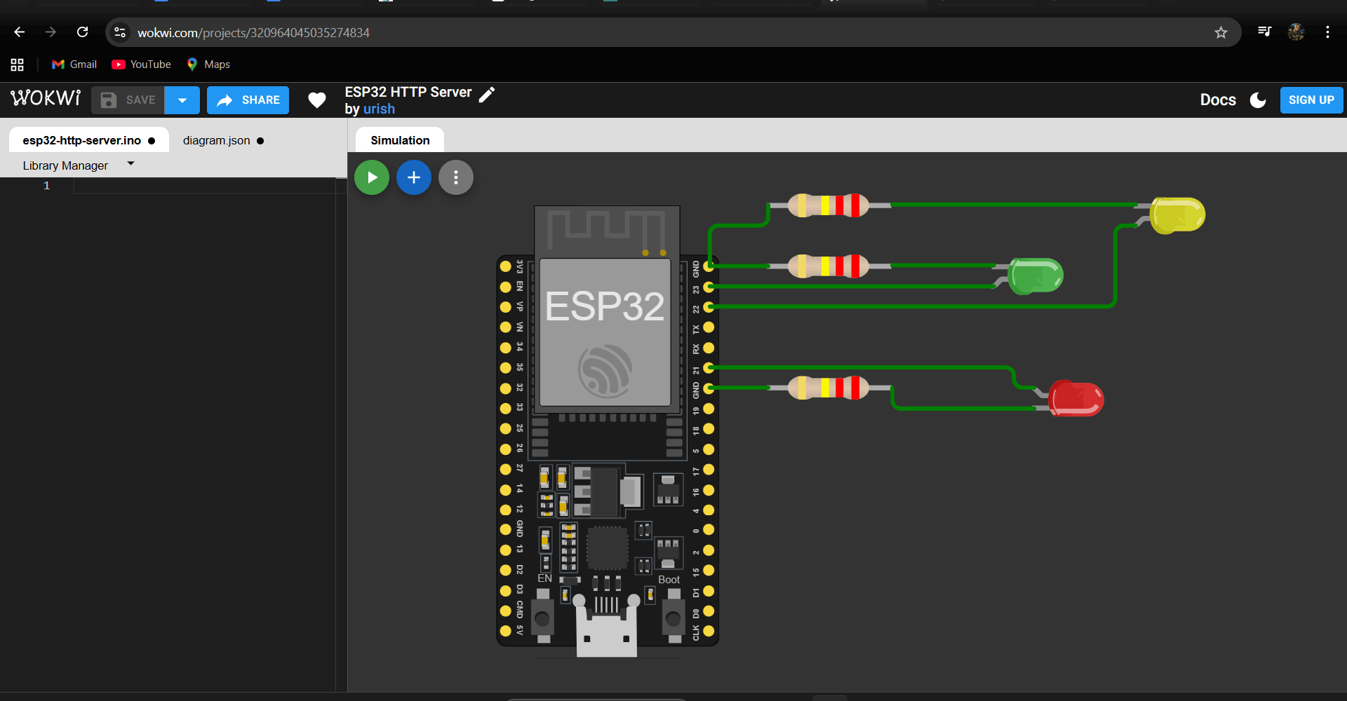
After that, I started connecting the components to the ESP32 pins correctly.
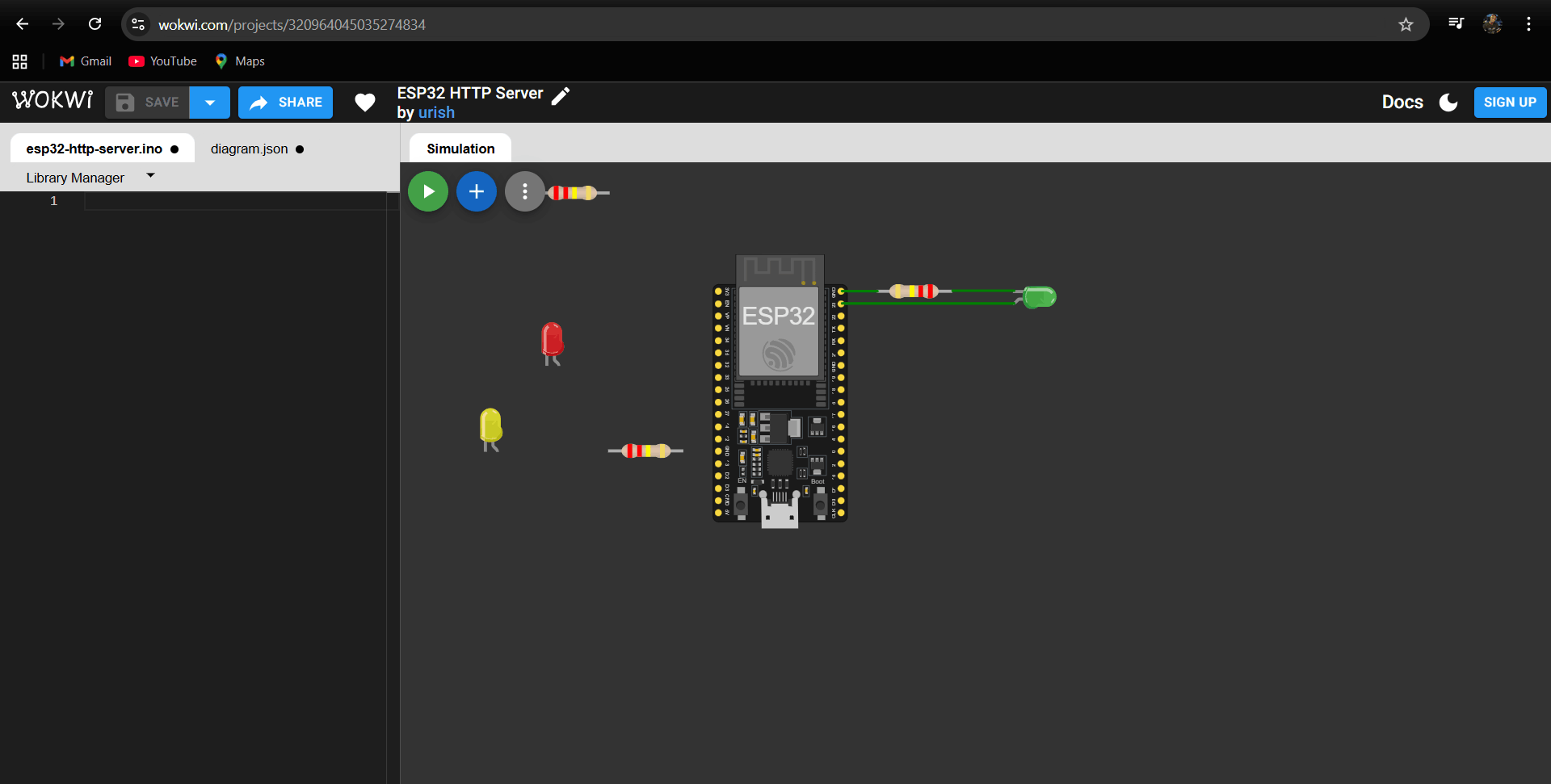
I connected the Green LED with the 220 Ω resistor to GPIO 23 of the ESP32
After that, I connected the other components, like the yellow and green LEDs with their 220 Ω resistors, to the ESP32 pins
Connection and programing
I connected the red, yellow, and green LEDs to the ESP32 using 220 Ω resistors on GPIO pins 23, 22, and 21. After completing the wiring, I wrote the code to control the LEDs in the traffic light sequence and ran the simulation to verify that each LED turned on and off at the correct time
After that, I started writing the code to control the traffic light
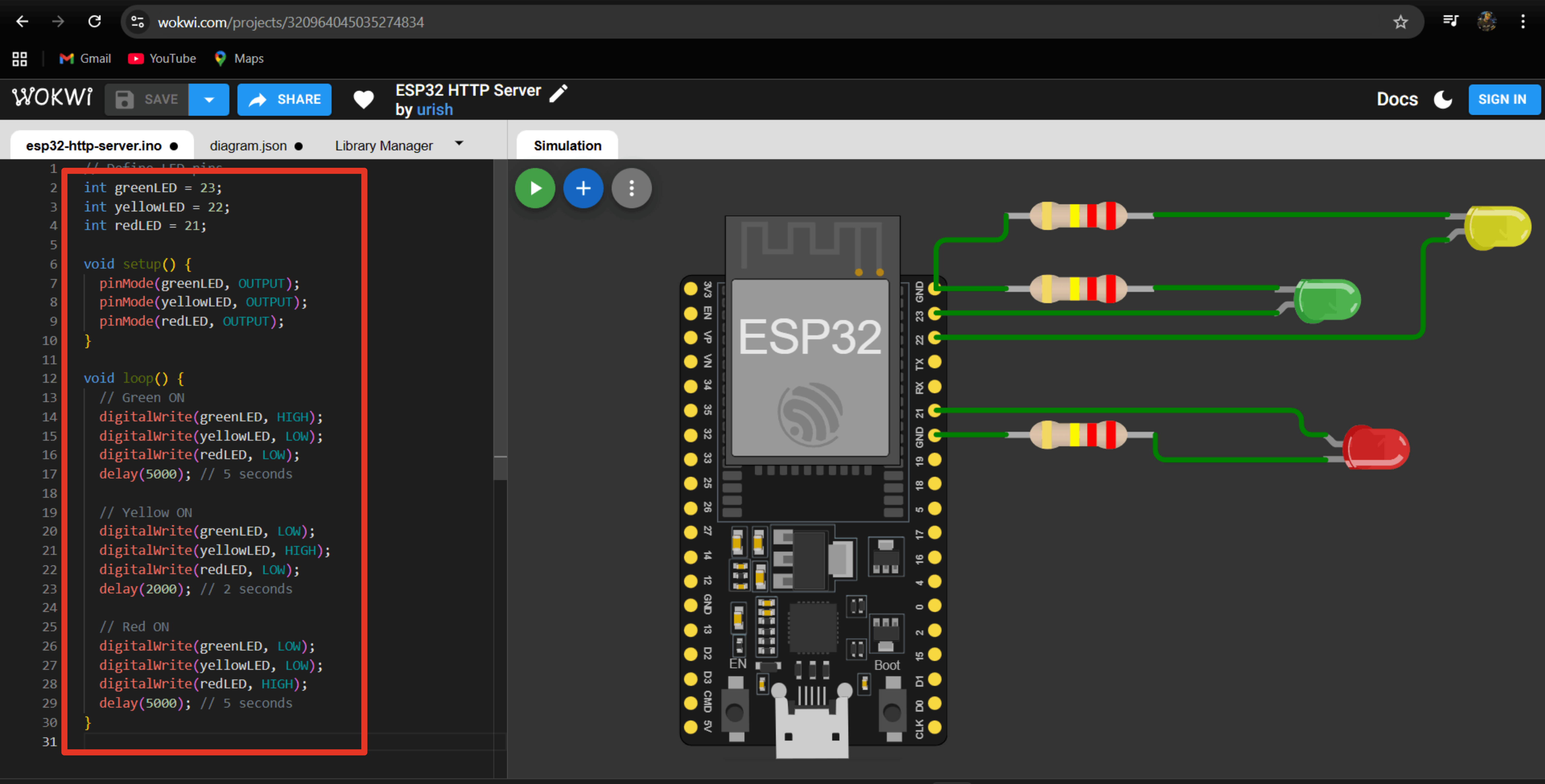
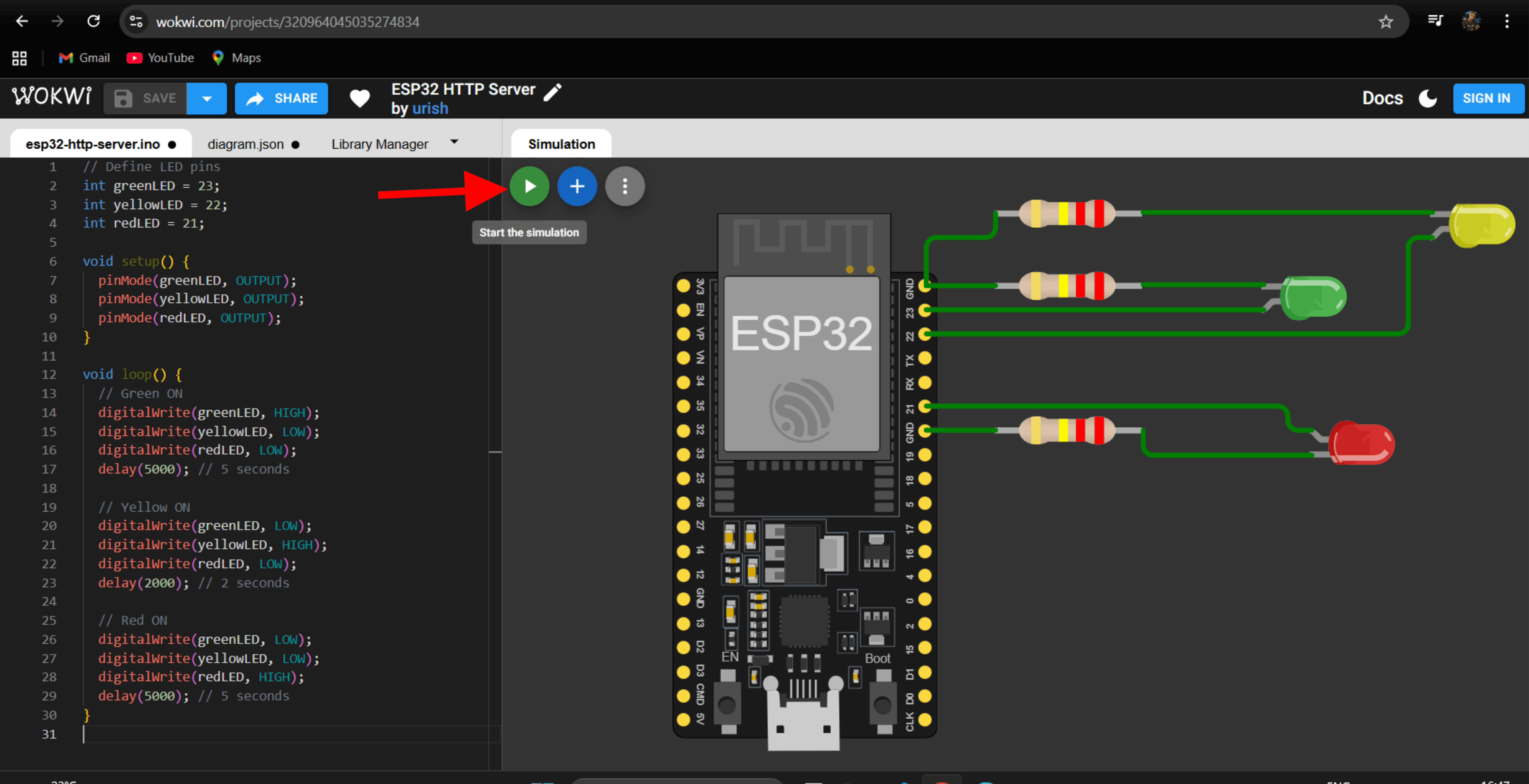
After writing the code, I started the simulation to test if the traffic light worked correctly
After running the simulation, I observed the results and confirmed that the traffic light sequence worked correctly, with each LED lighting up for the set time
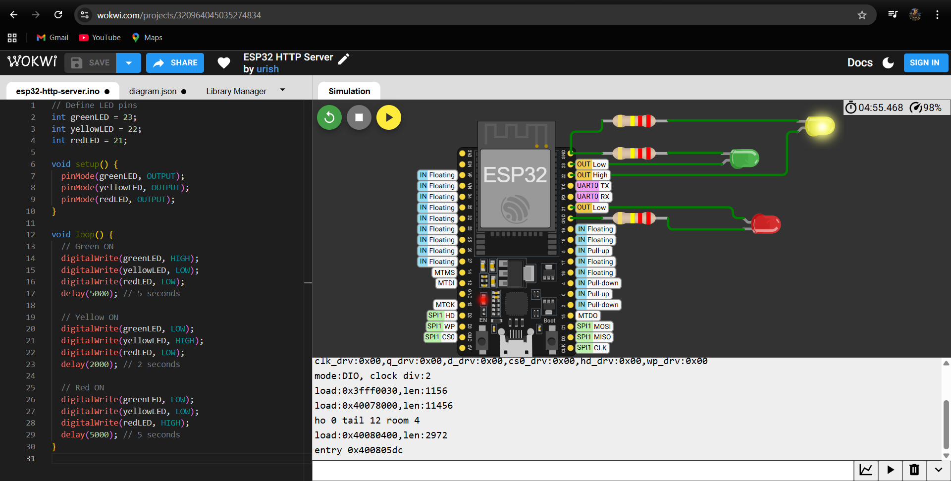
After, I recorded a video of the simulation showing the traffic light in action, demonstrating that the LEDs changed correctly according to the programmed sequence
The Wokwi project was programmed using the following code
// Define LED pins
int greenLED = 23;
int yellowLED = 22;
int redLED = 21;

void setup() {
  pinMode(greenLED, OUTPUT);
  pinMode(yellowLED, OUTPUT);
  pinMode(redLED, OUTPUT);
}

void loop() {
  // Green ON
  digitalWrite(greenLED, HIGH);
  digitalWrite(yellowLED, LOW);
  digitalWrite(redLED, LOW);
  delay(5000); // 5 seconds

  // Yellow ON
  digitalWrite(greenLED, LOW);
  digitalWrite(yellowLED, HIGH);
  digitalWrite(redLED, LOW);
  delay(2000); // 2 seconds

  // Red ON
  digitalWrite(greenLED, LOW);
  digitalWrite(yellowLED, LOW);
  digitalWrite(redLED, HIGH);
  delay(5000); // 5 seconds
}