Assignment
Group assignment
Our group completed the lab safety training to learn safe operation, material handling, and emergency procedures for using the laser cutter. We then characterized the laser cutter by testing focus, power, speed, kerf, joint clearance, and different cutting types. These tests helped us understand how machine settings affect cut quality and accuracy. All results and observations were documented on the group work page this the Link
Individual Reflection:
Through this assignment, I learned how to safely use a laser cutter and how adjusting parameters like focus, power, speed, and kerf is essential for precise and well-fitting design
Laser cutting
The part was designed and modeled in SOLIDWORKS, including all partitions and parametric joints.
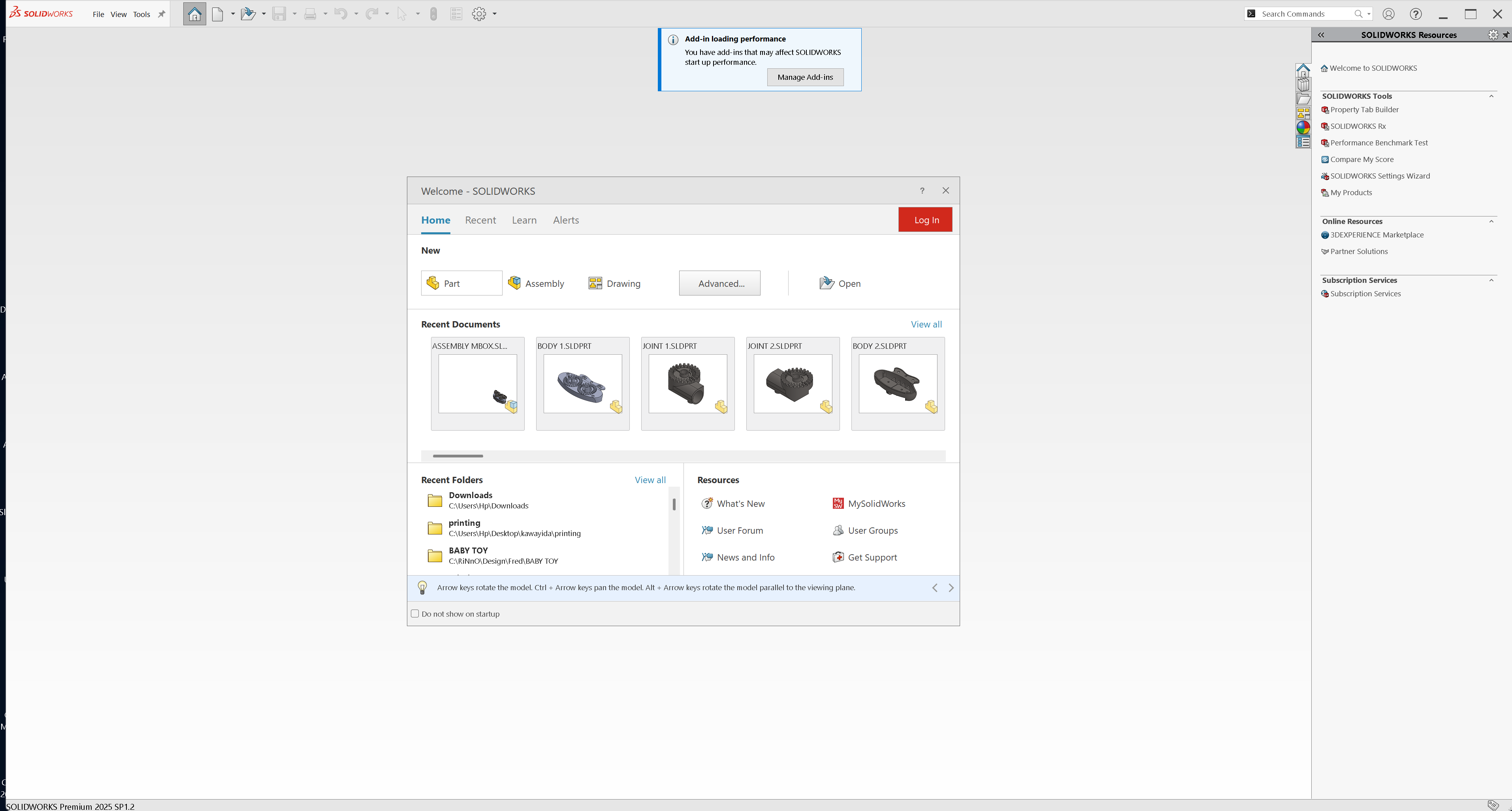
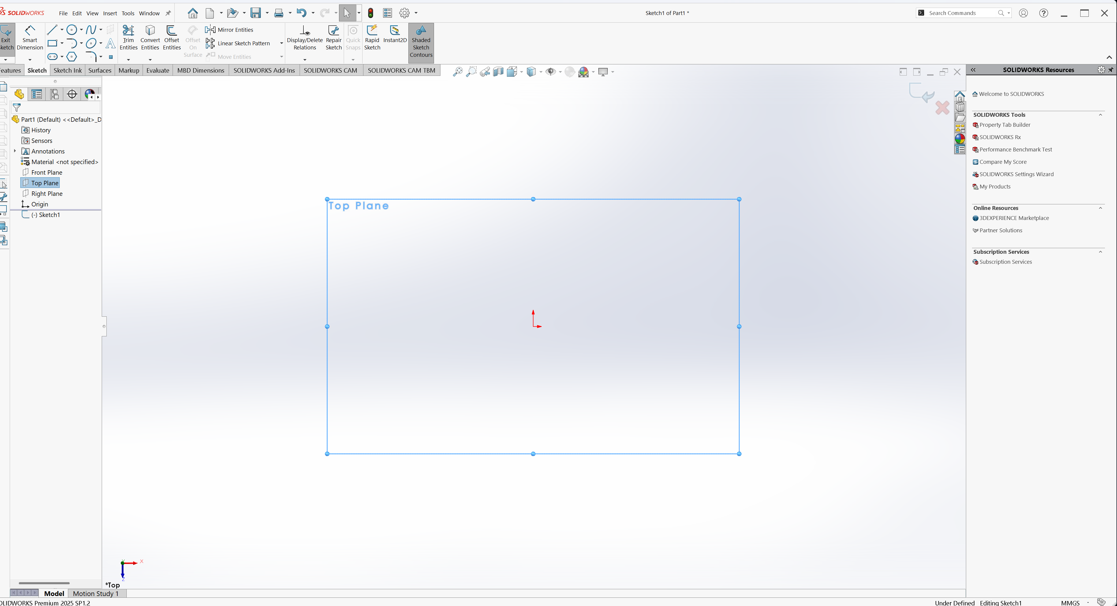
First, open SOLIDWORKS. Then, create a new file by selecting Part to begin the sketching process
Select the Top Plane
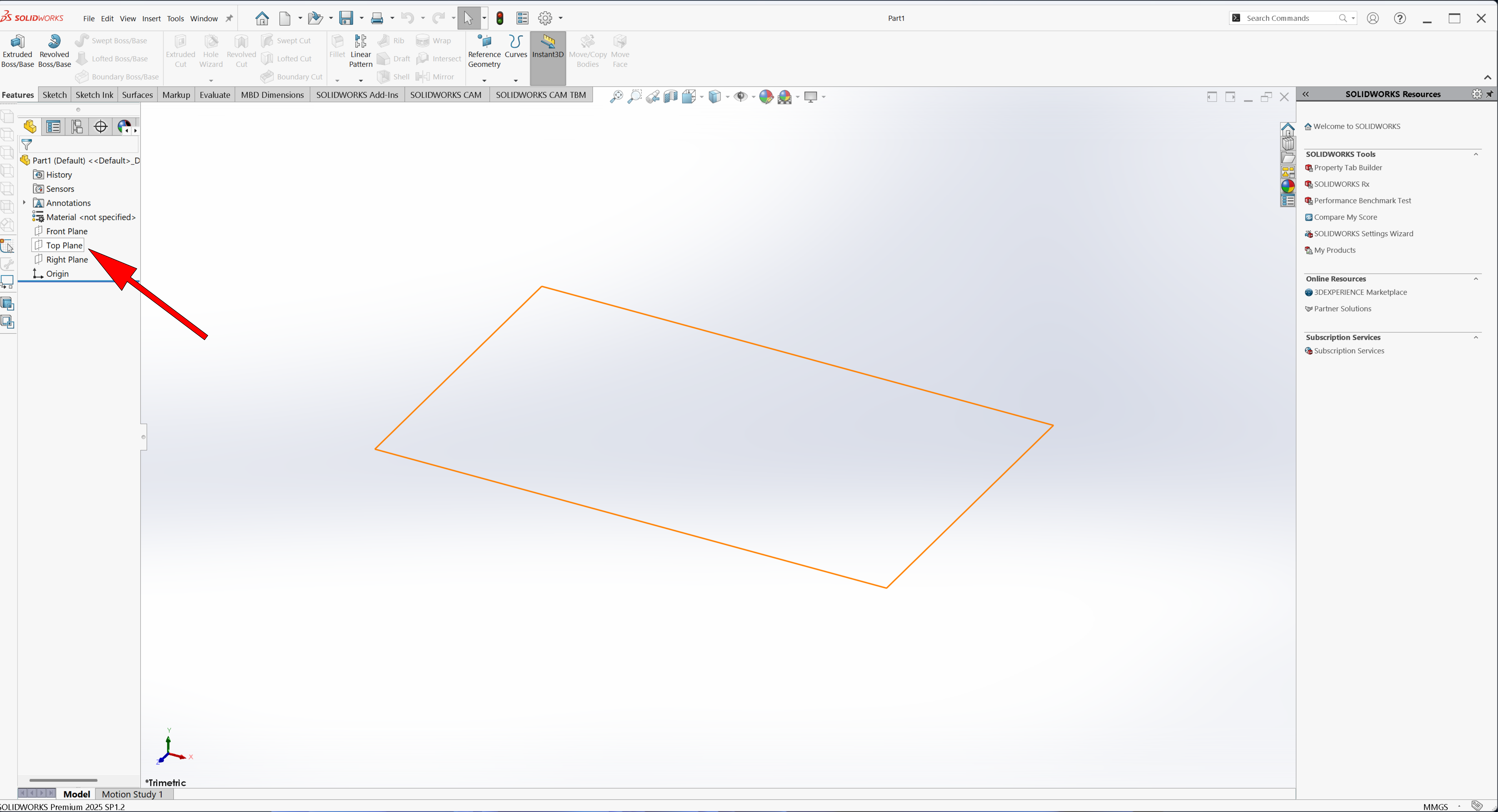
Click “Sketch” to start drawing
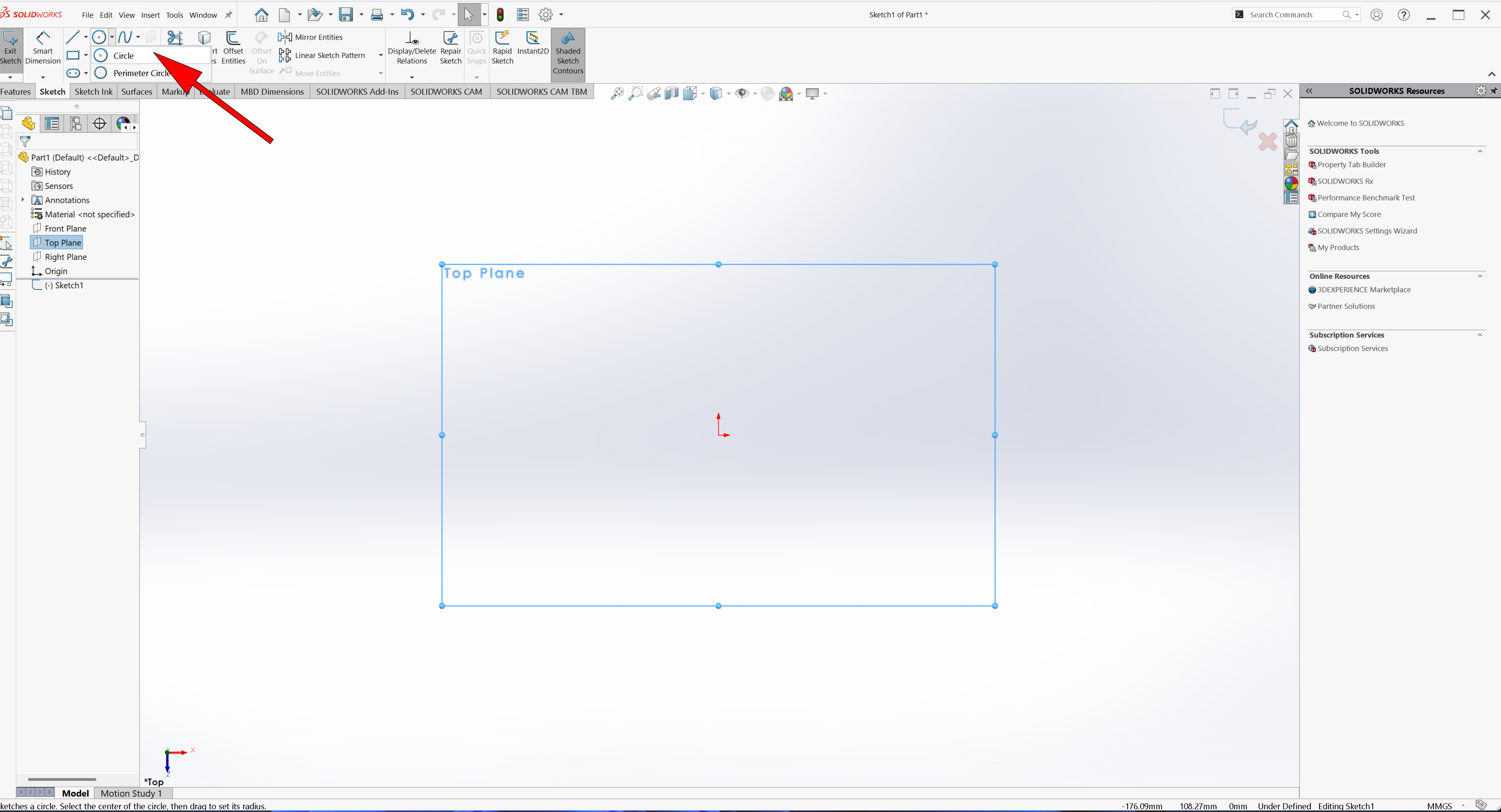
Select the Circle tool from the Sketch toolbar
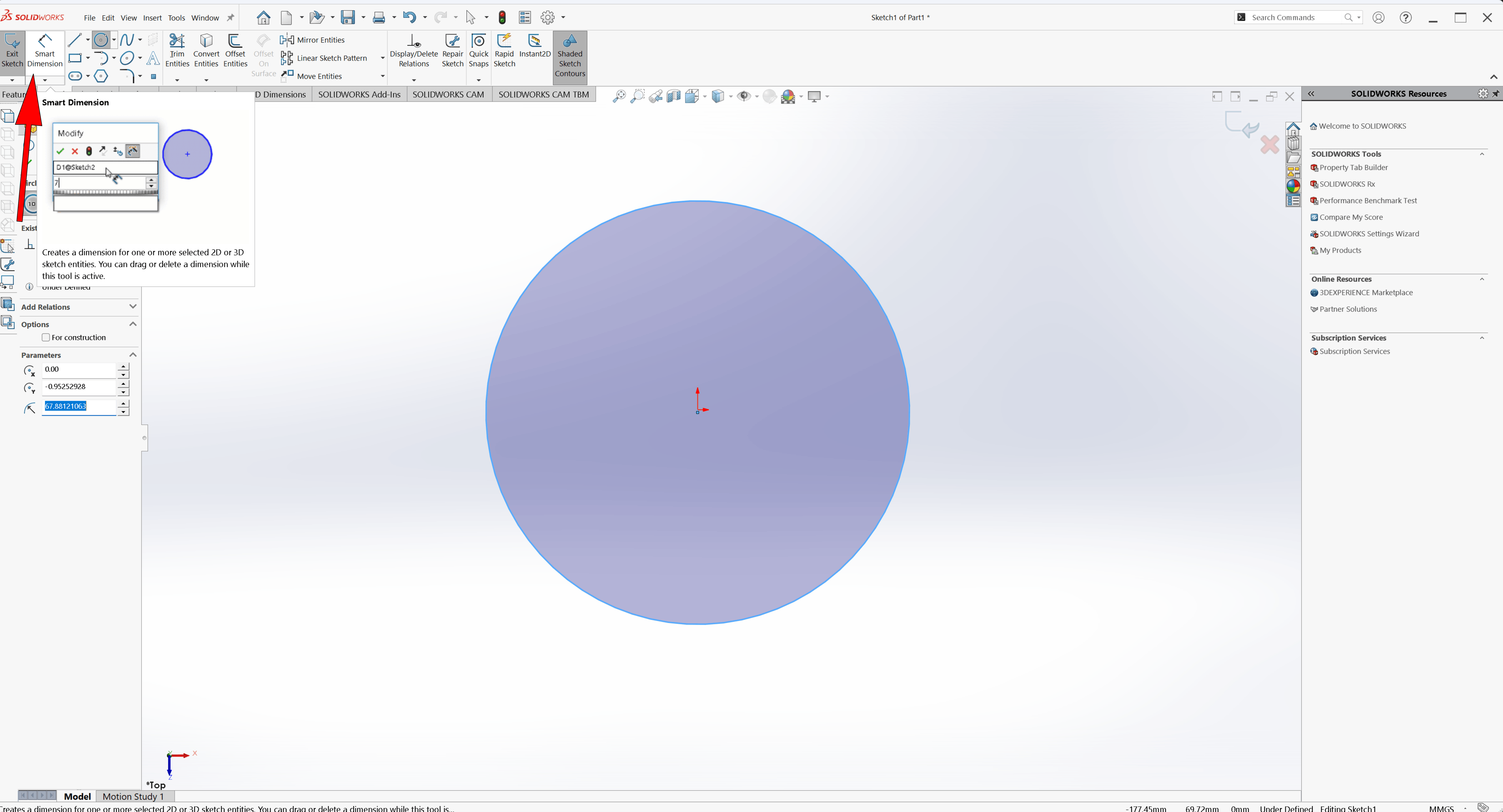
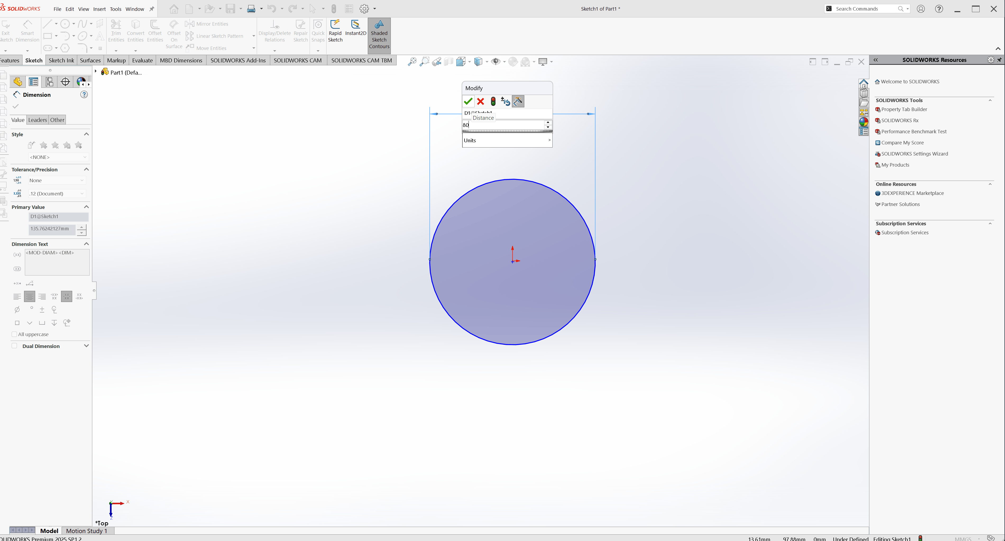
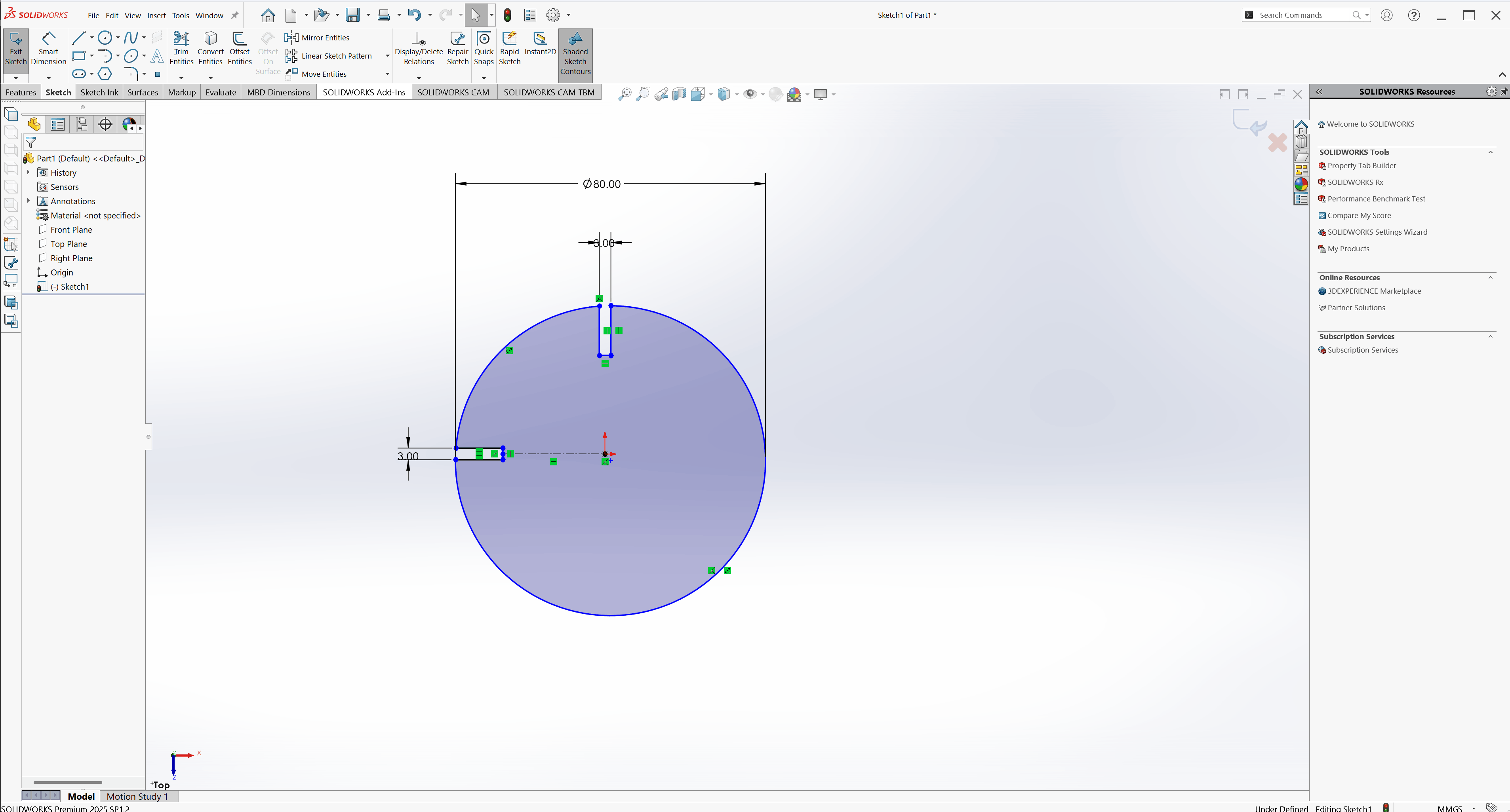
After selecting the Circle tool, draw a circle from the origin point. Then, apply Smart Dimension and set the circle diameter to 80 mm
Sketch the partition layout And, Apply parametric constraints and dimensions to define the joint accurately
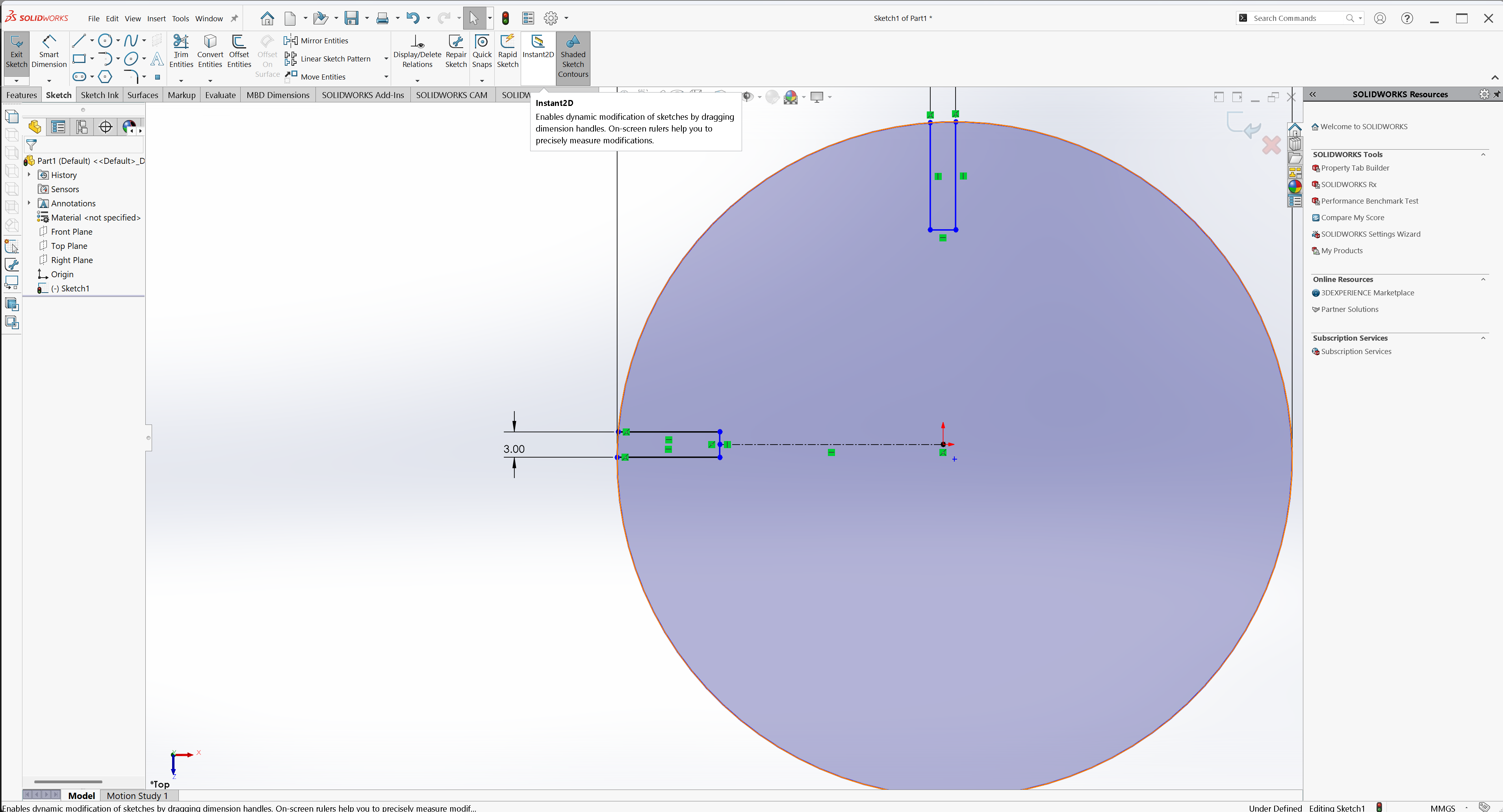
Position the lines at the center using center line tool, of the circle using the origin as a reference and Use the Trim Tool to remove extra lines
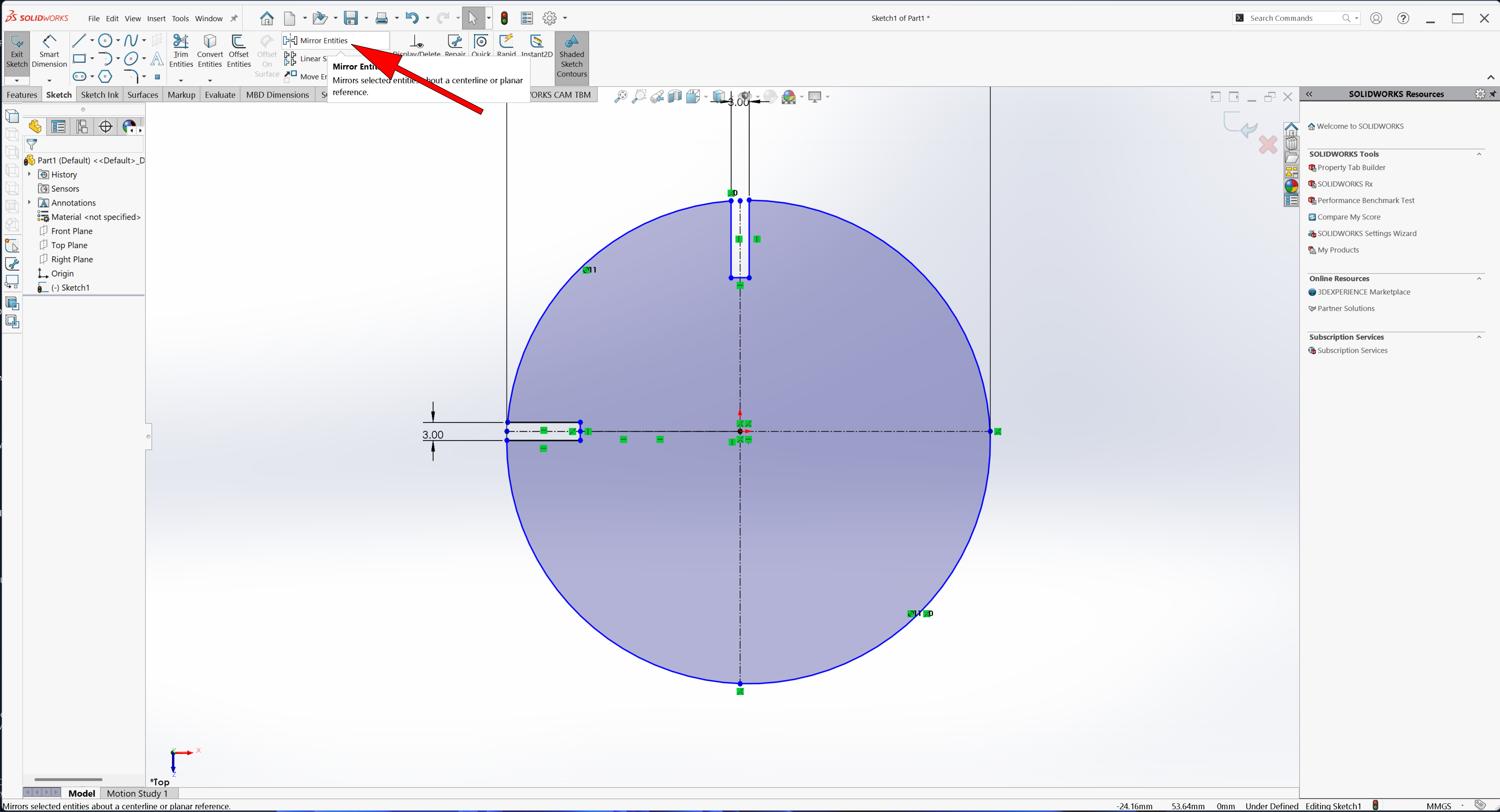
Mirror the joint lines using the centerline as the mirror axis
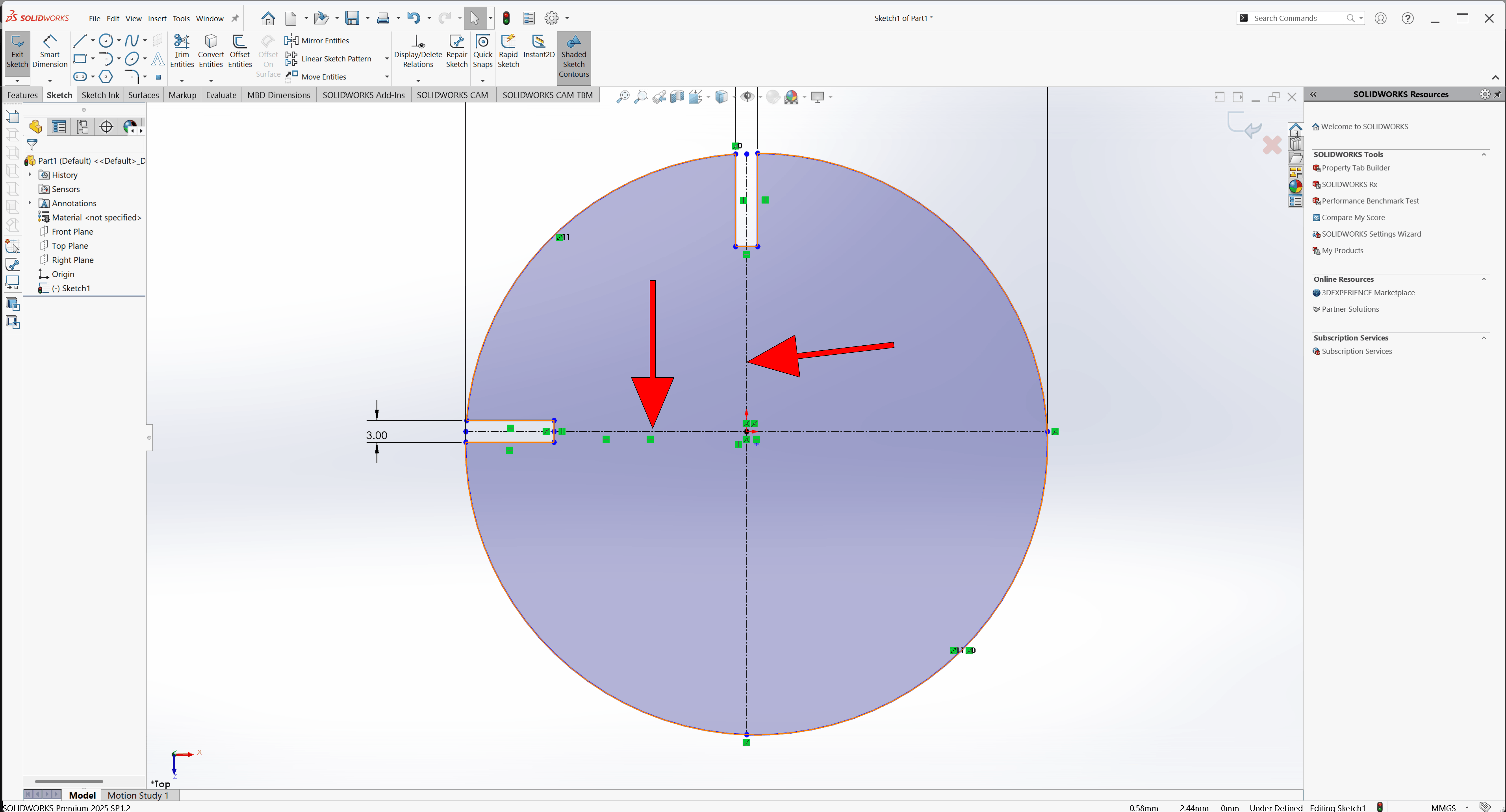
Use the Mirror tool to replicate the joint symmetrically across the center or partition axes.
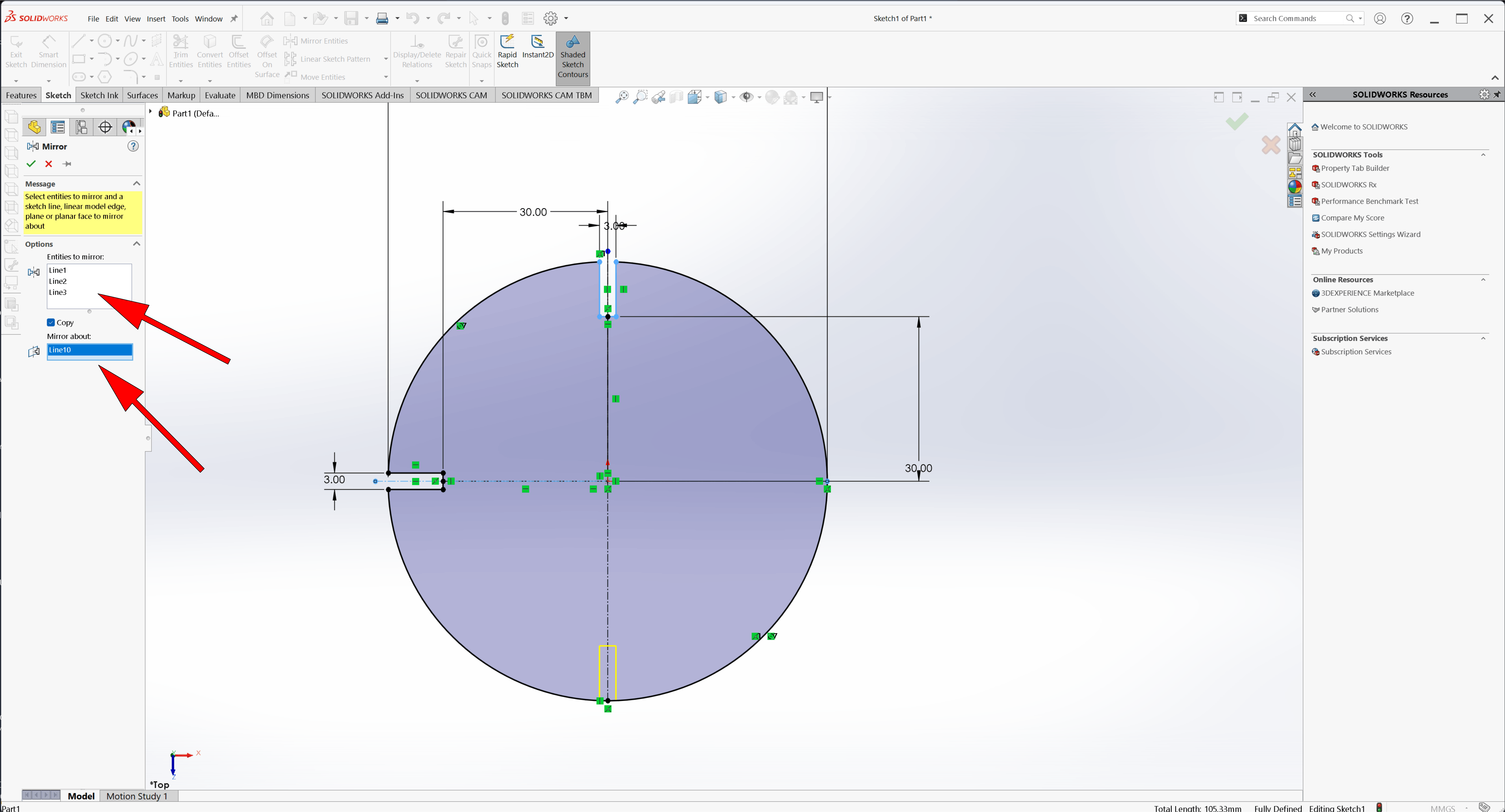
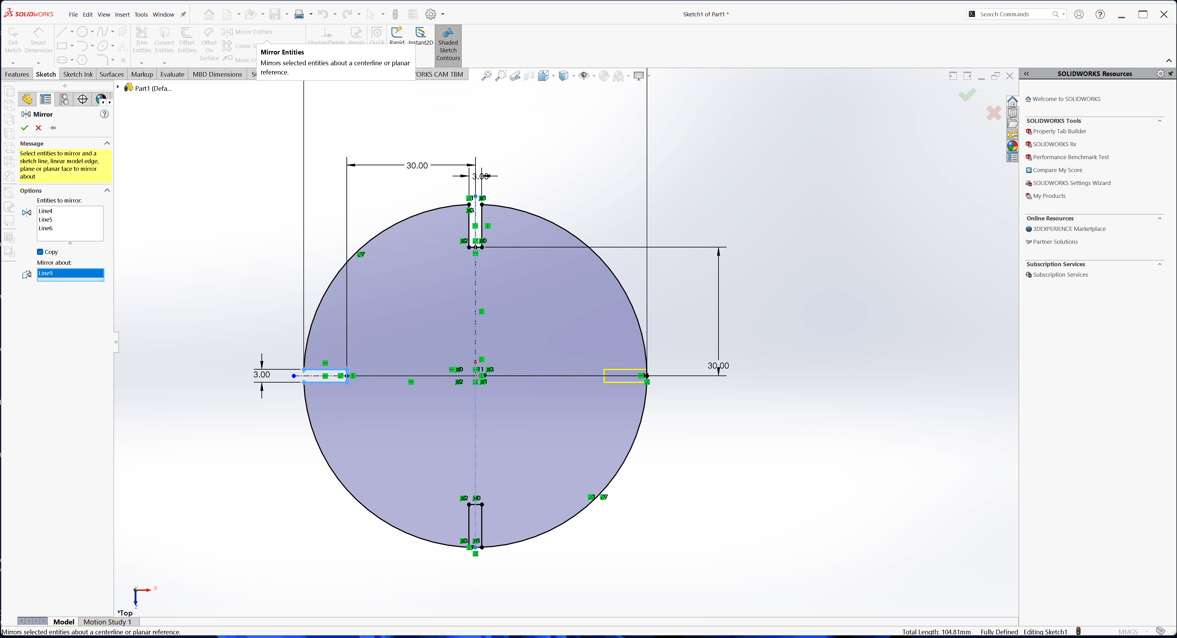
Add a second centerline perpendicular to the first, and mirror again
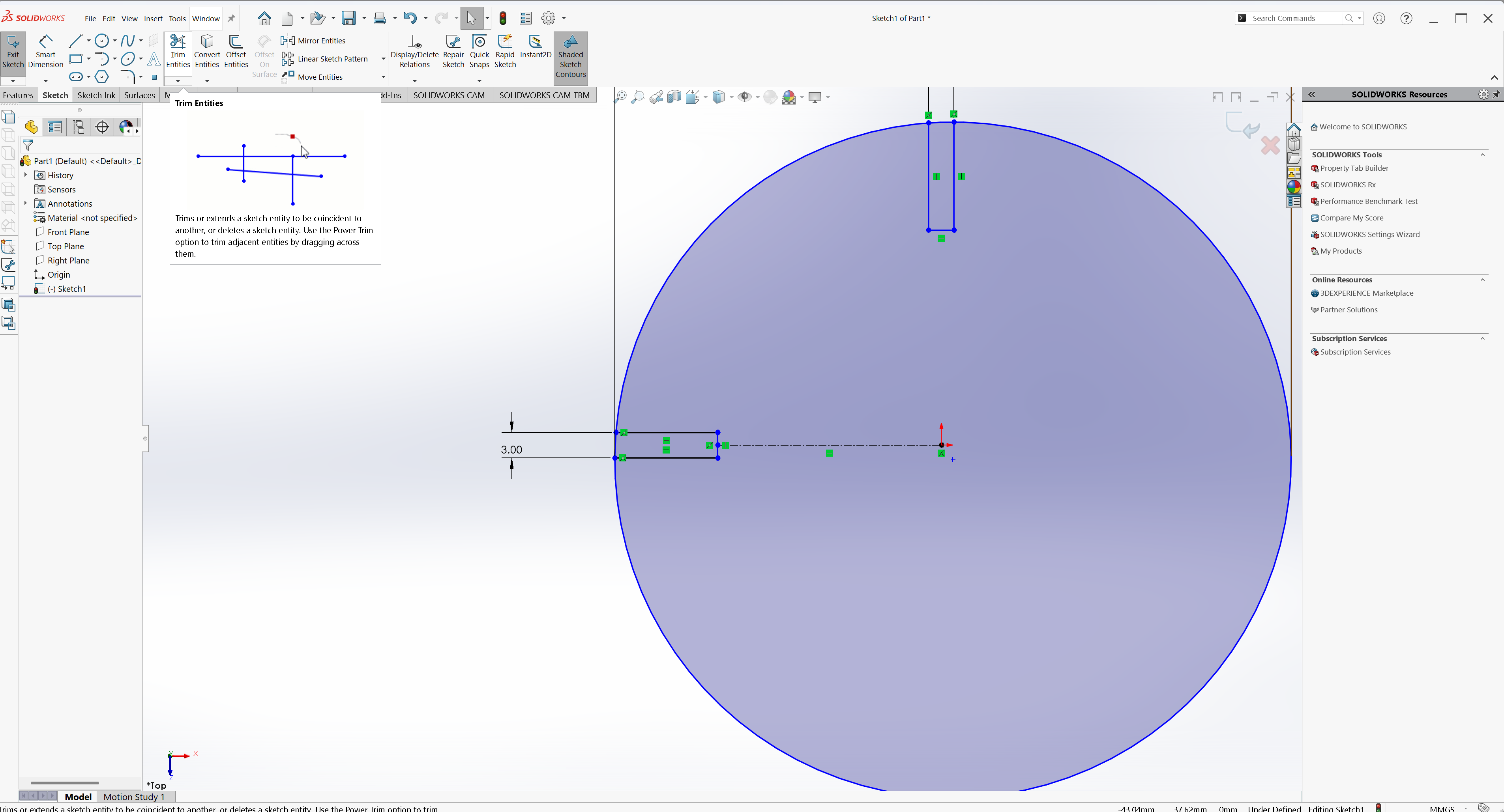
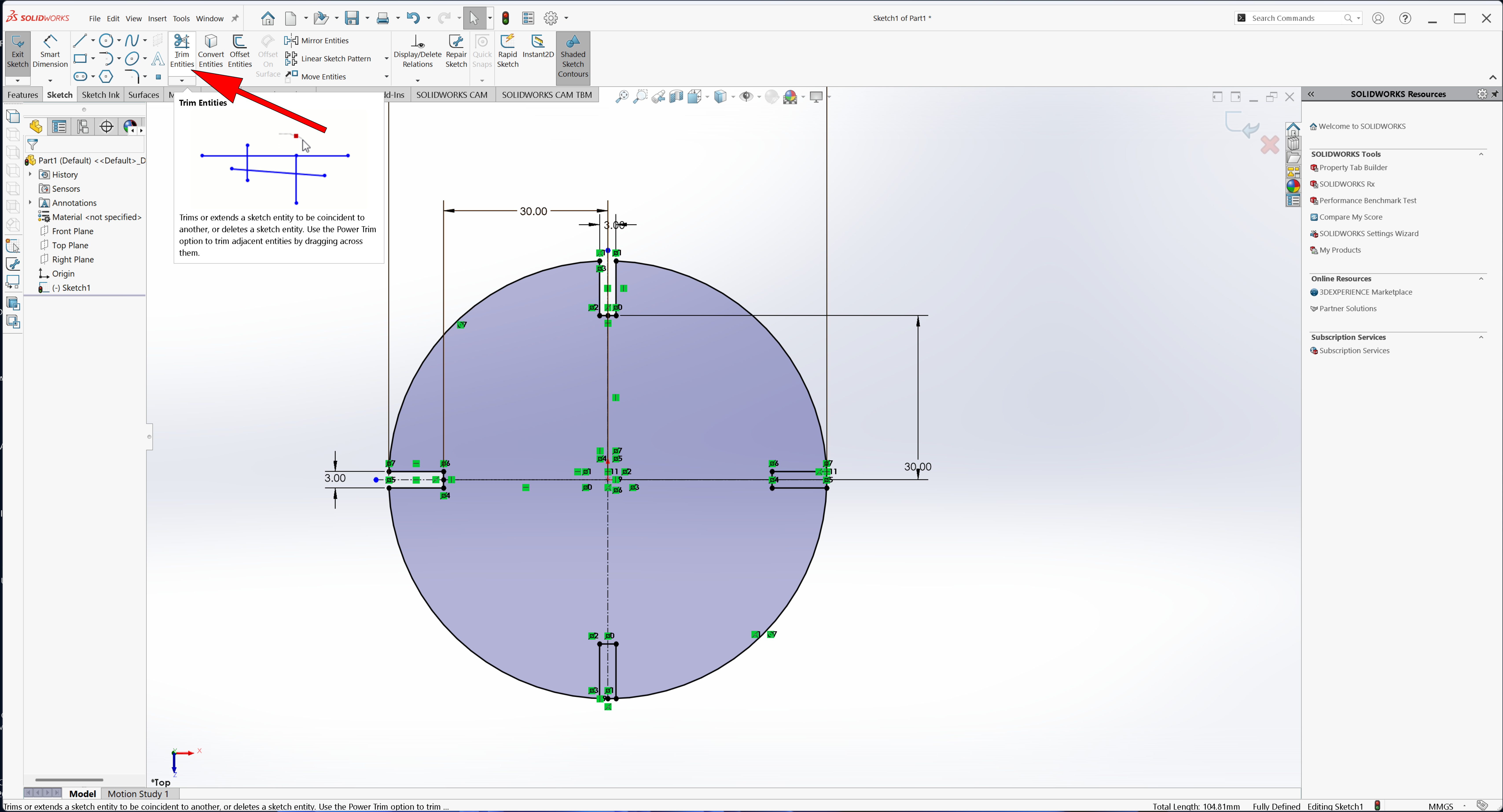
The next step is trimming the extra lines created by the mirror
The final sketch is fully, with all joint lines mirrored correctly across all centerlines Next, Use Extruded Boss/Base to give thickness to the sketch and create the 3D partitions/joints
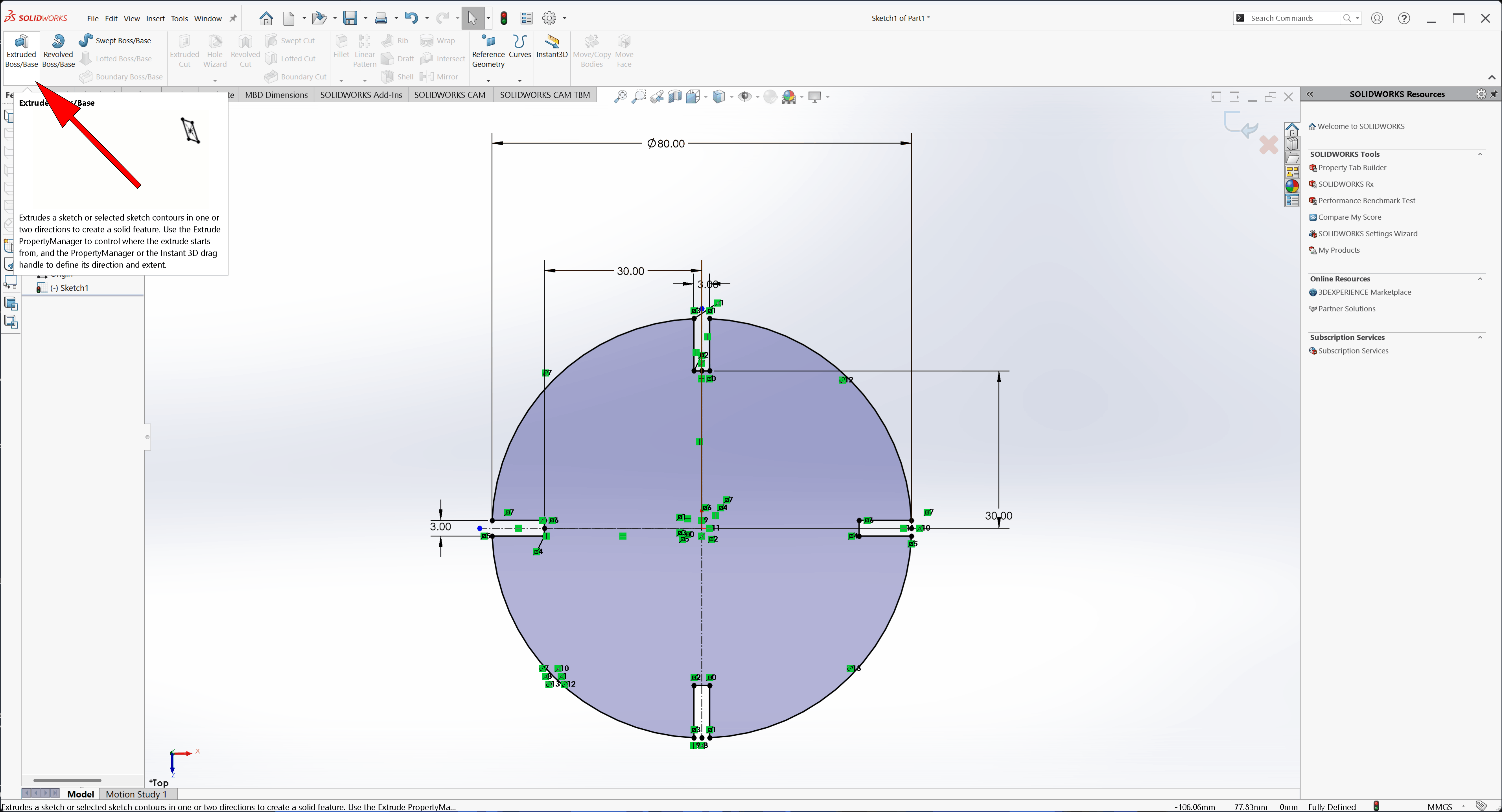
Extrude the sketch to 3 mm thickness to define the material thickness
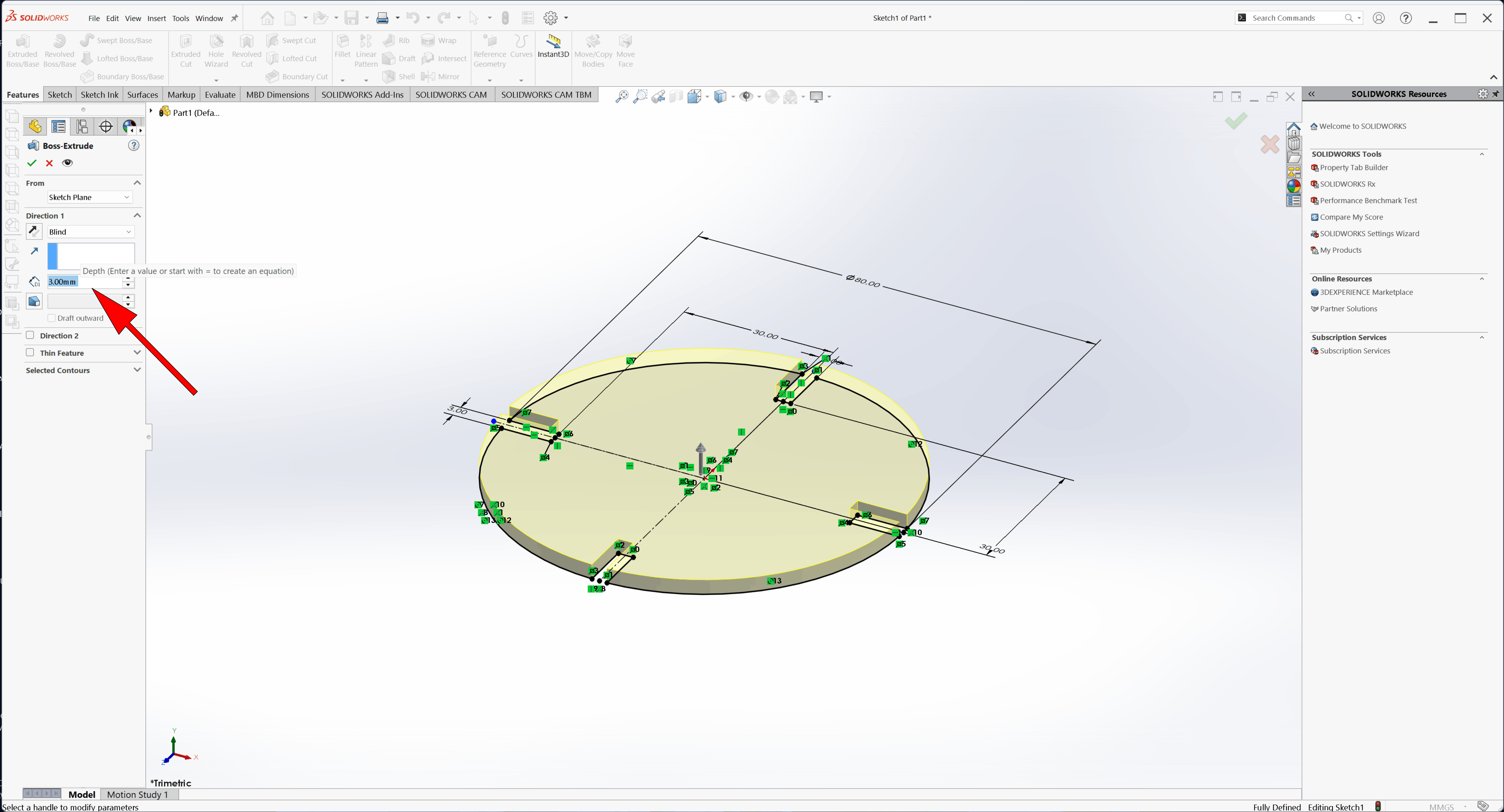
Final 3D part with 3 mm thickness
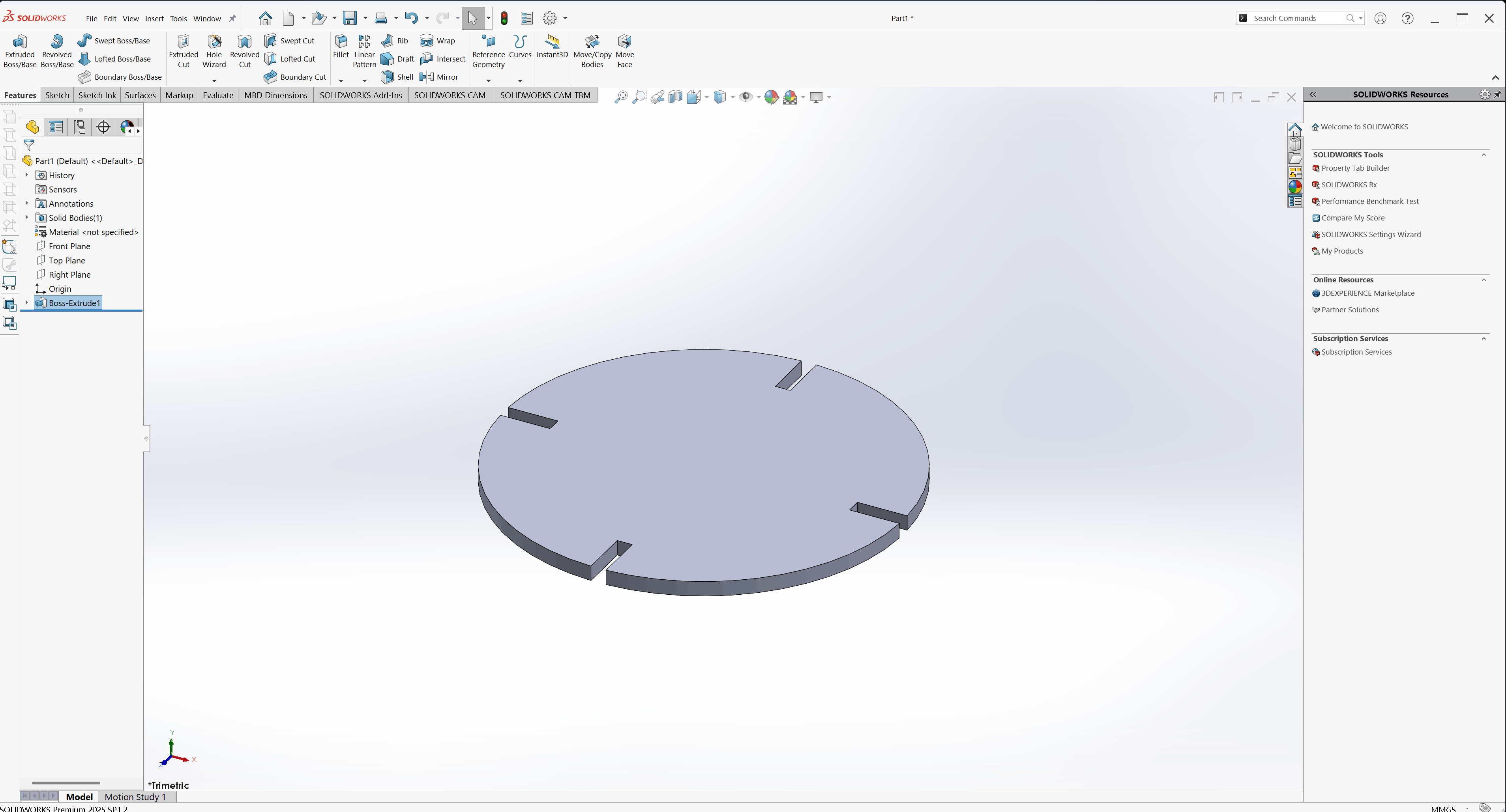
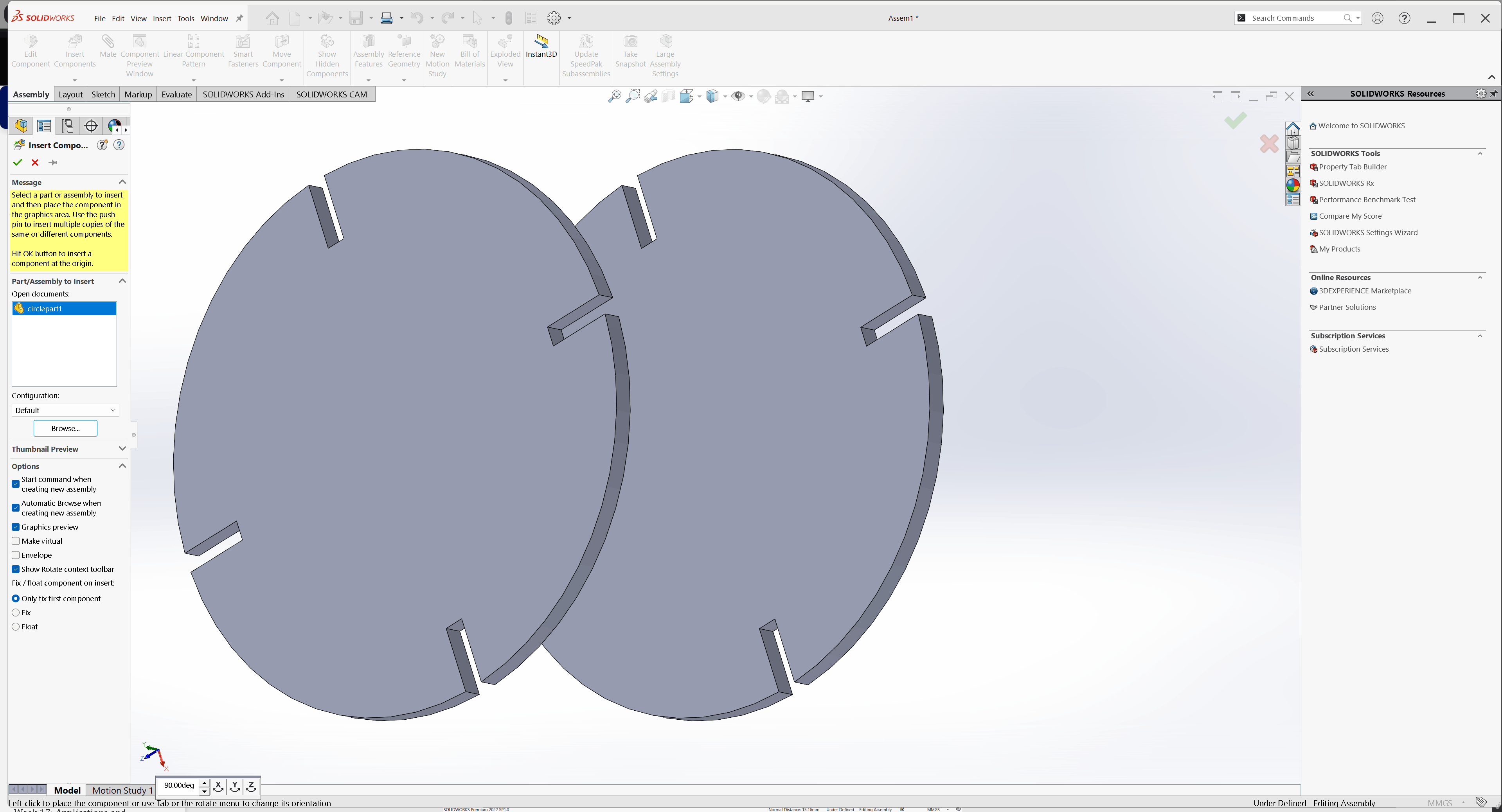
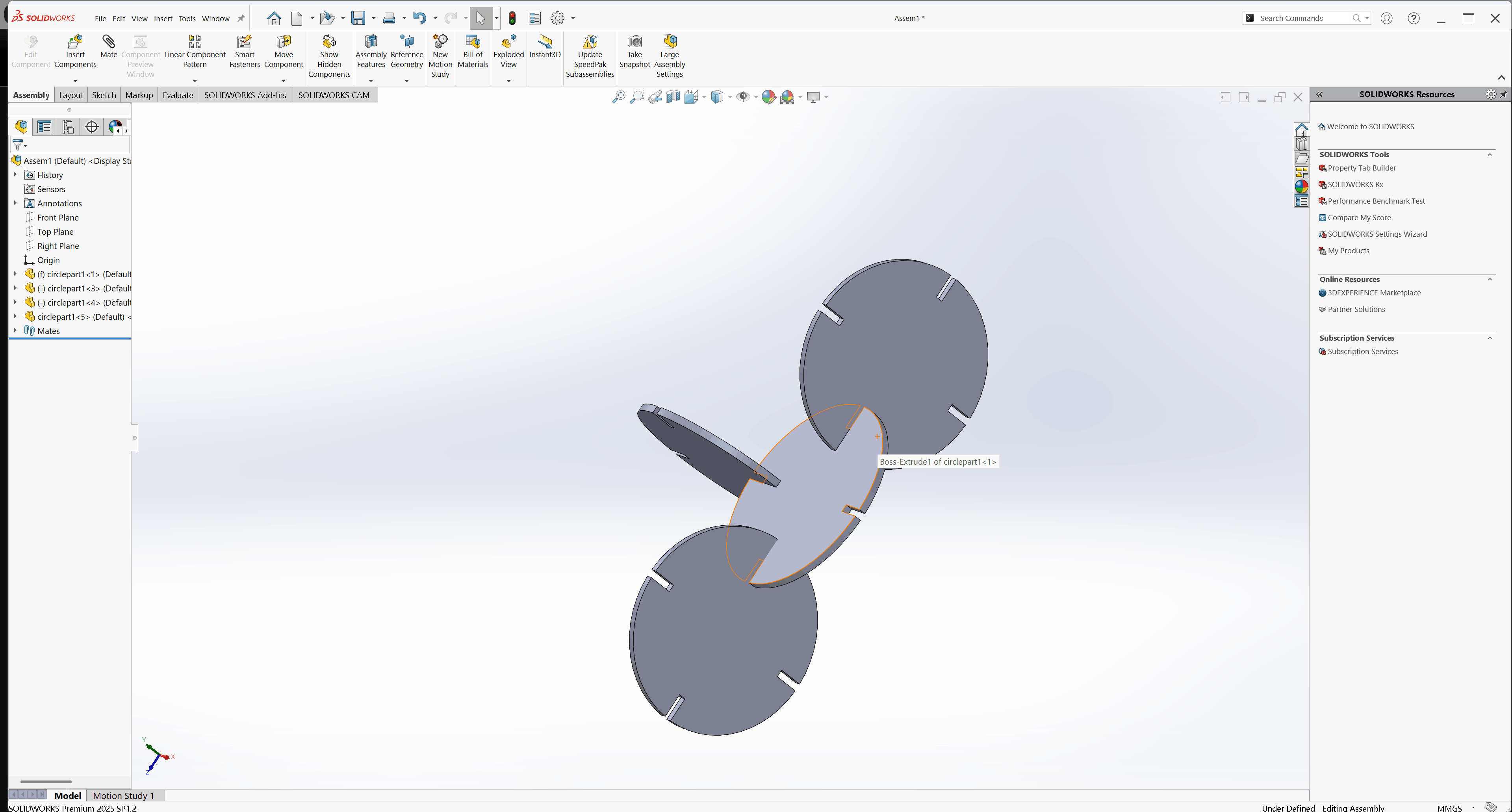
The next step is to use Assembly to combine parts
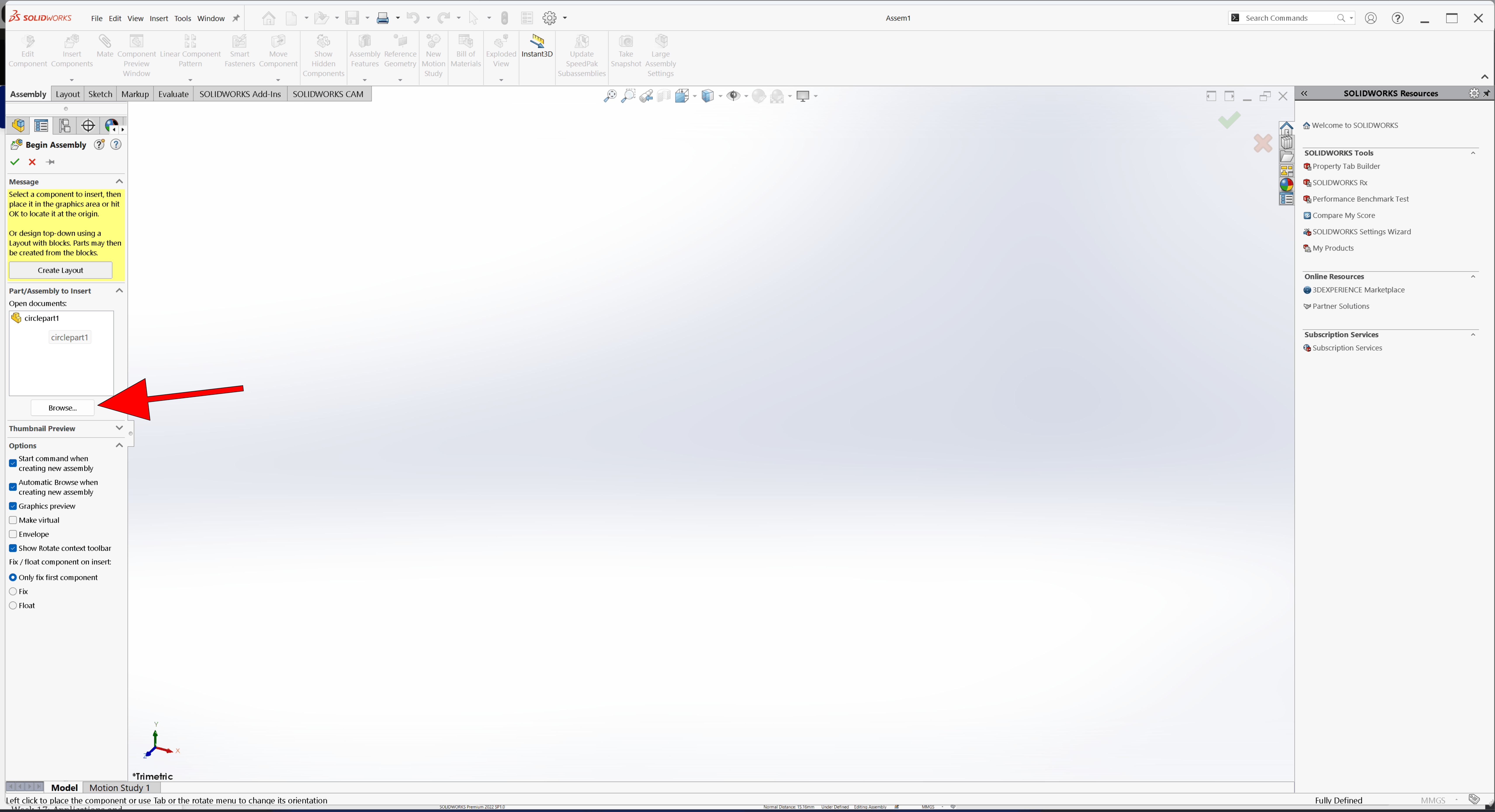
Both parts have been added to the assembly
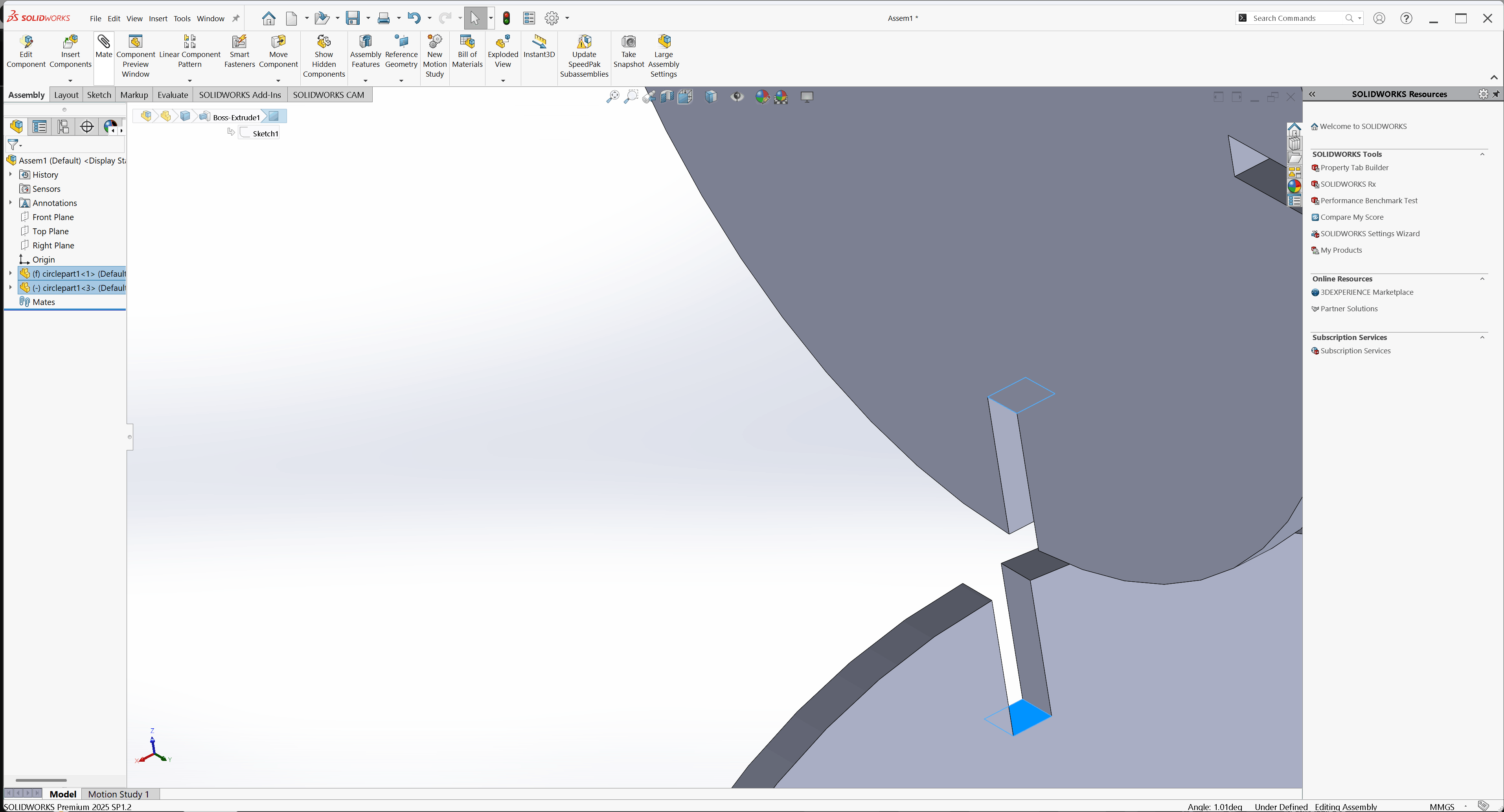
Rotate the object to make mating easier.
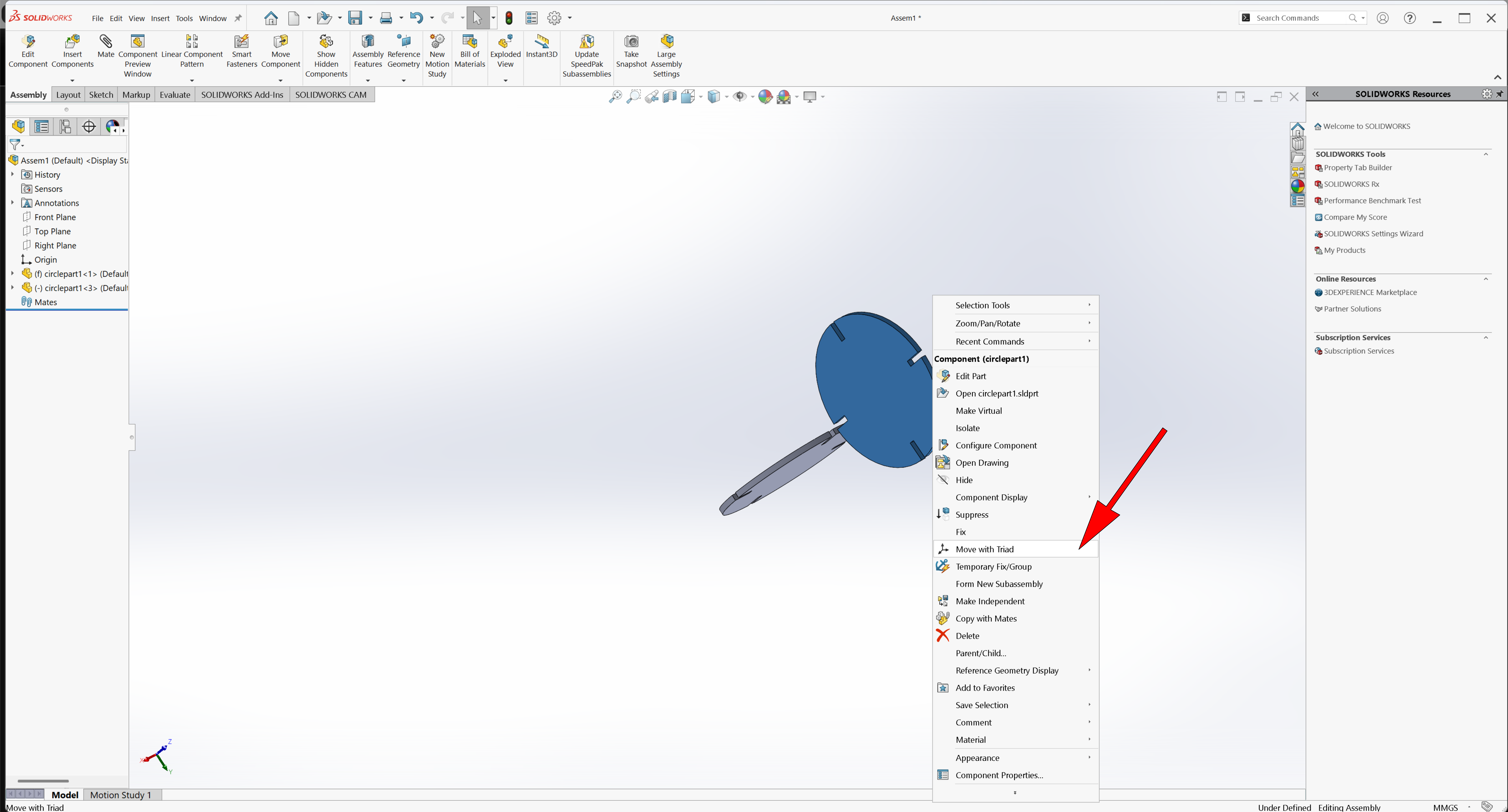
Select the parts you want to mate and click the Mate tool
The parts are already mated
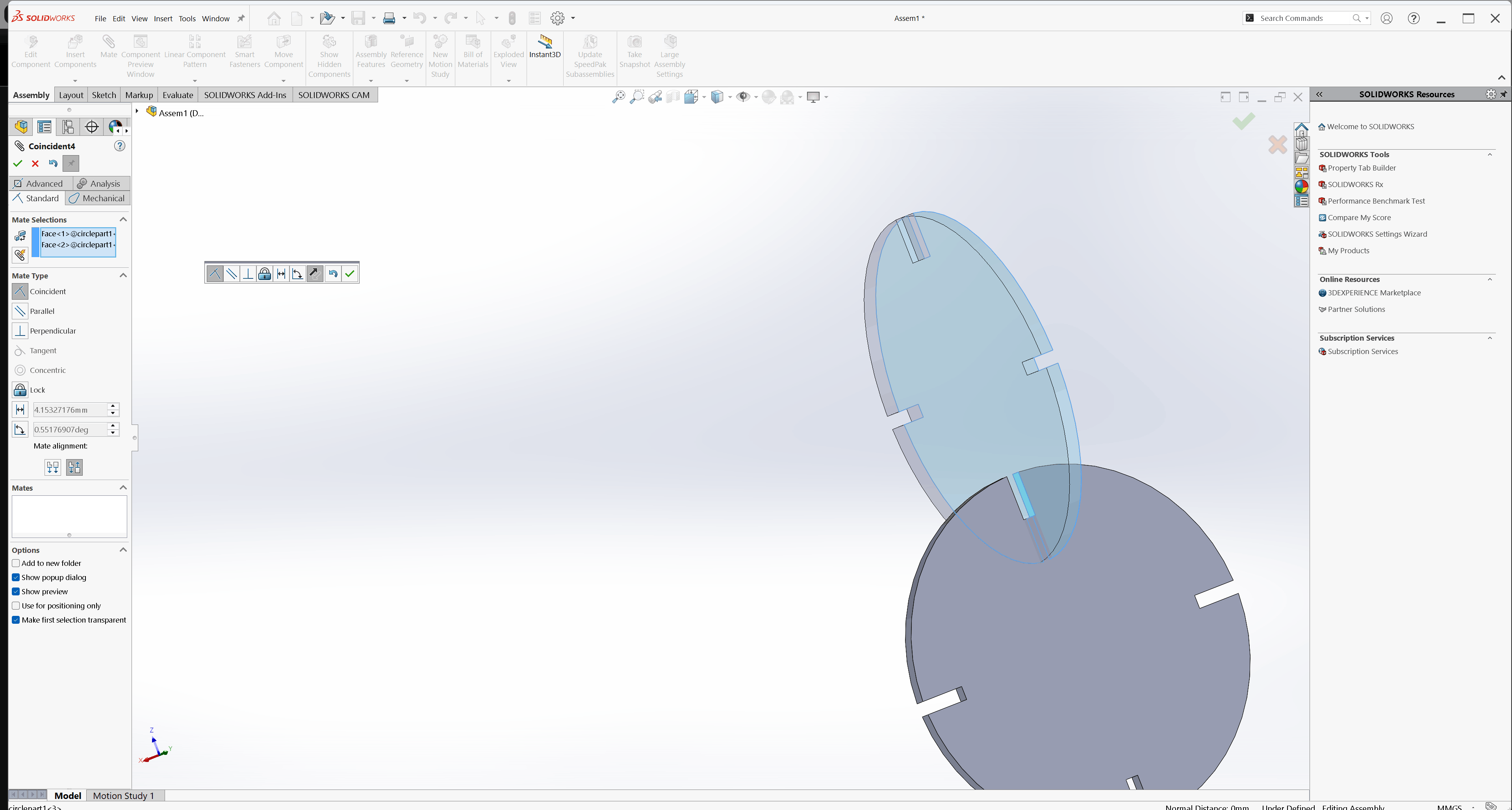
Add the third part to the assembly and apply mates
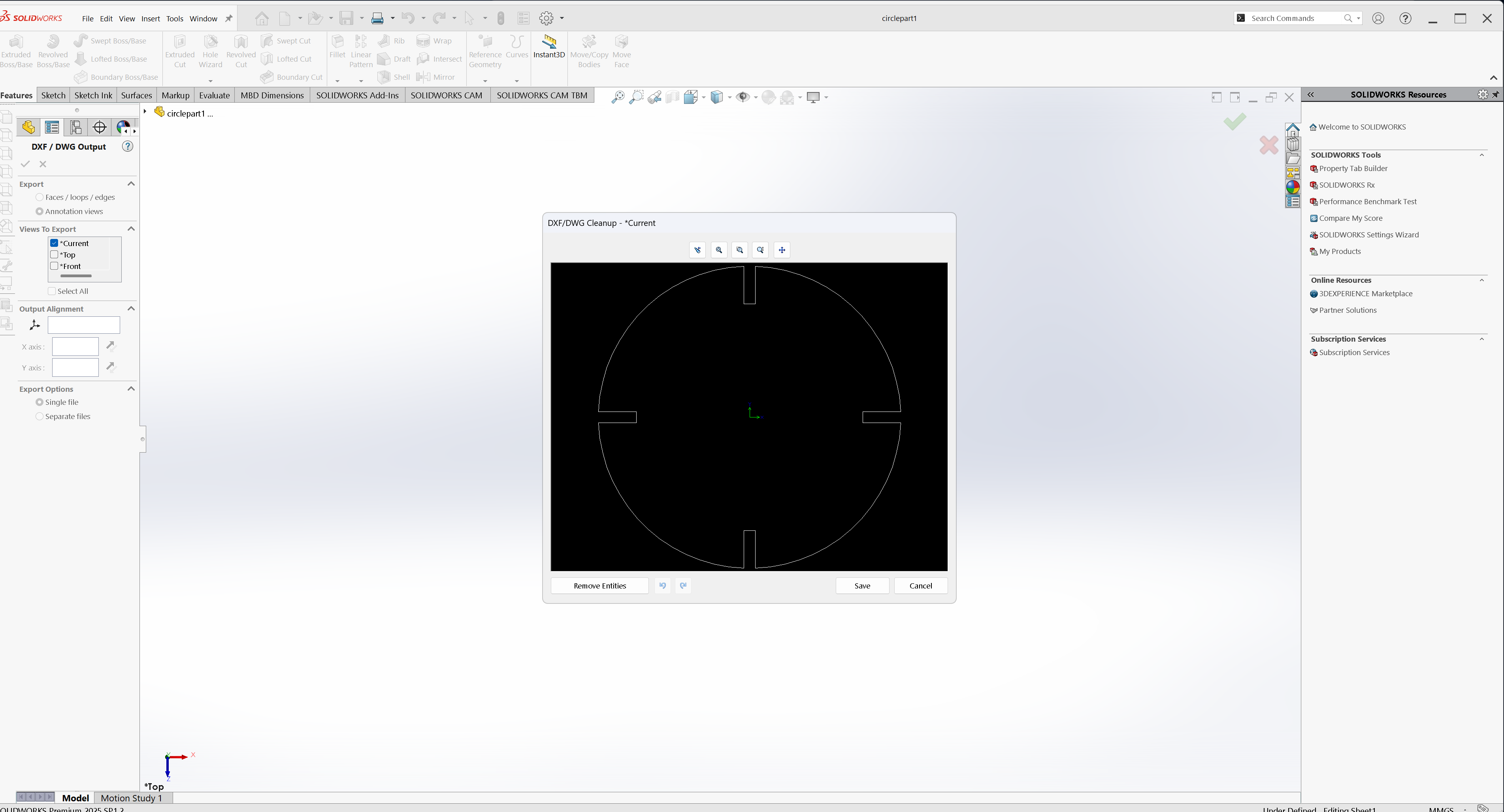
After verifying that the assembly was correct, the assembly project was saved. Next, I returned to the individual part drawing and exported it as a DXF file, which will be used for laser cutting
After, I importing the design into LightBurn, I created an array of the design, specifying the number of copies I needed to cut
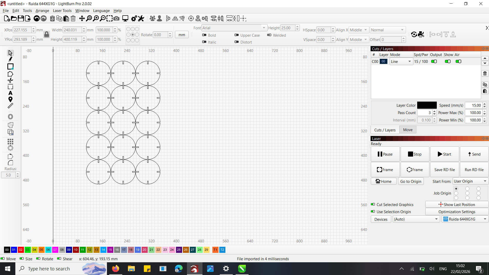
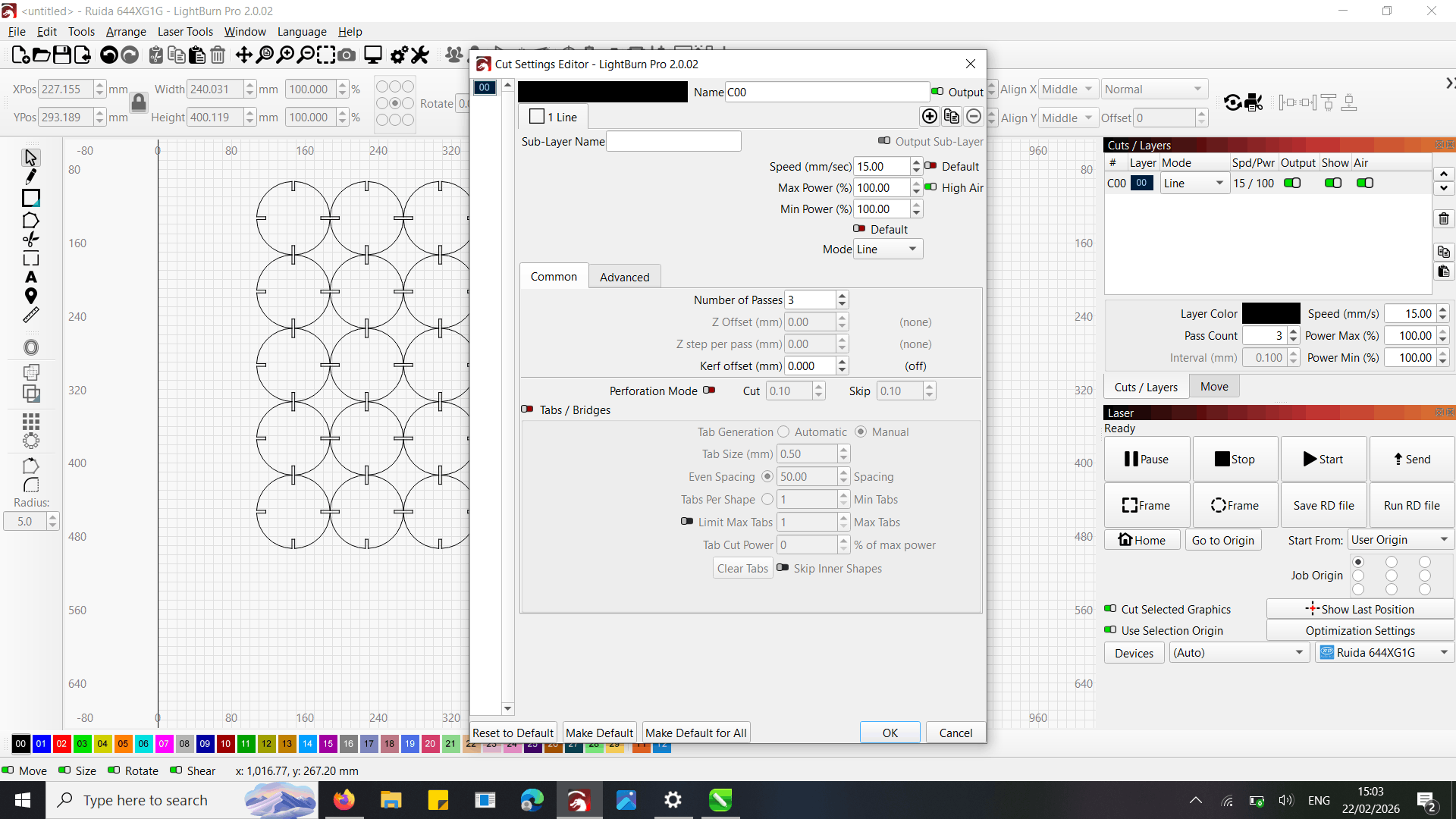
I adjusted the cutting settings such as power, speed, and passes based on what we learned as a group.
.After placing the material on the laser bed
I went to the menu and selected the autofocus option to ensure the laser beam was correctly focused for precise cutting.
After setting the autofocus and verifying all settings, I started the laser cutting process. The laser successfully cut the material according to the design
After laser cutting the sheets, I assembled the pieces according to the design. The components fit together accurately, forming the intended structure
vinyl cutter
vinyl cutter is machine that uses computer guided blade to precisely cut designs, letters, and graphics from thin vinyl sheets commonly used for stickers
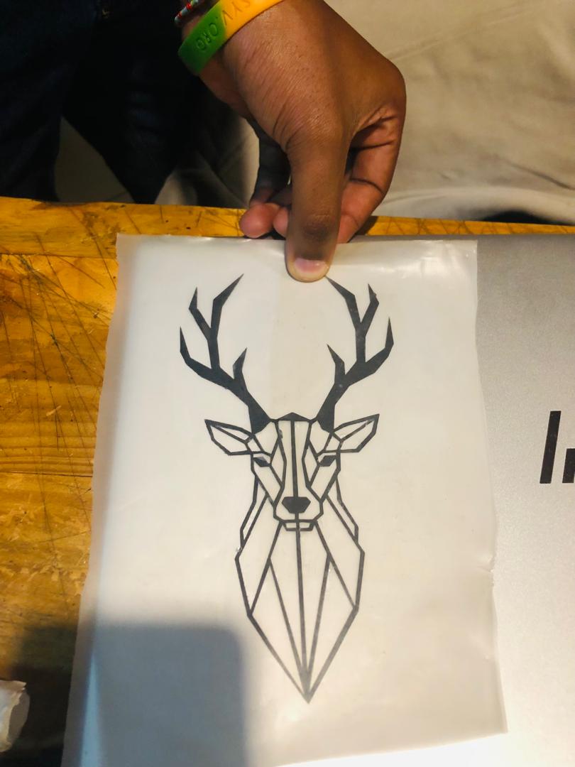
Using Coreldraw, i opened my design i created during the Computer Aided Design week and set to hairline for precise cutting and resized it
After preparing the design I placed the black sticker in the vinyl cutter and covered the sensor and adjusted the pinch rollers to hold the material
Next, I selected sheet and pressed enter to see the size
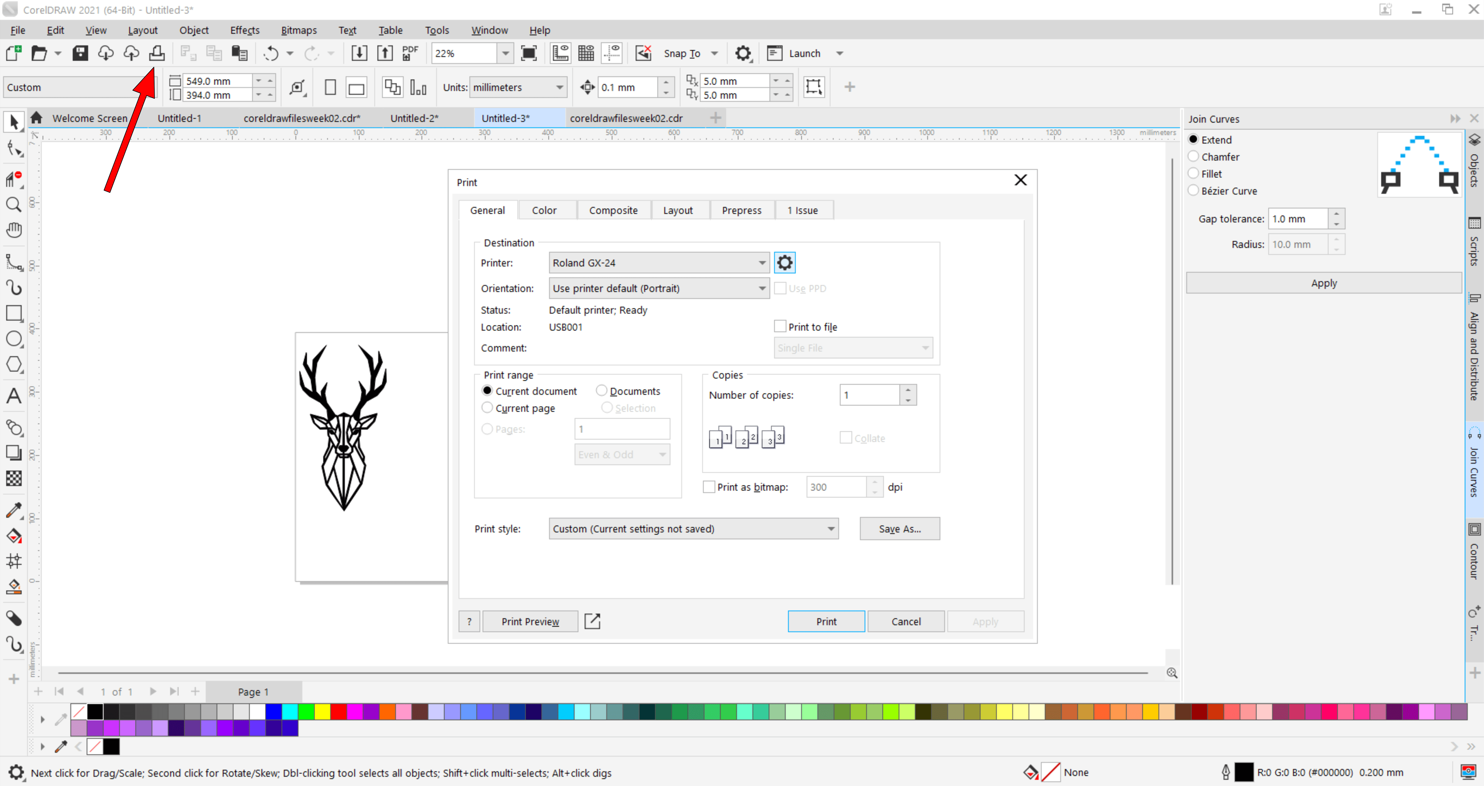
Then I returned to CorelDRAW, pressed print, and chose Roland GX-24
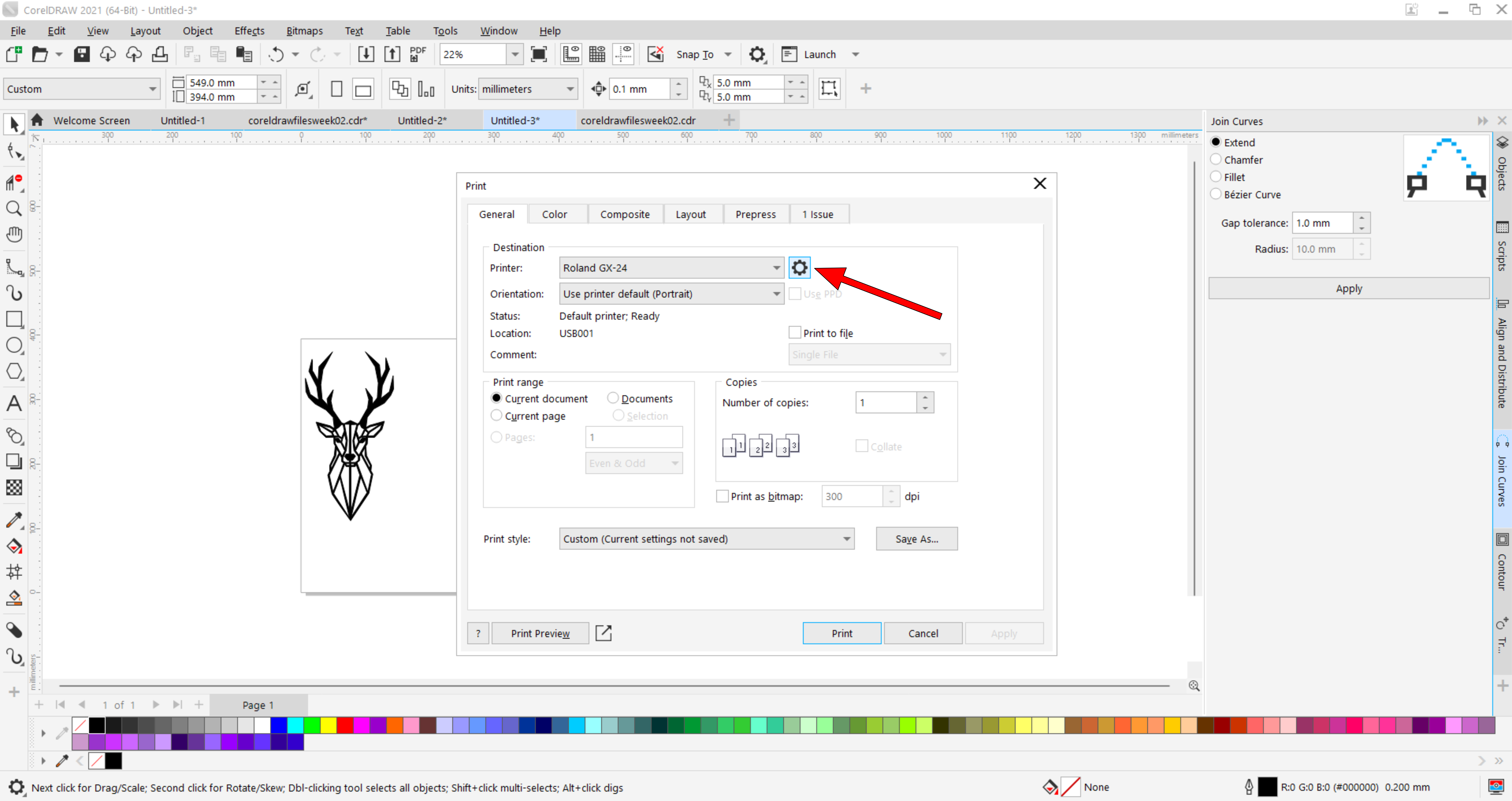
Then i opened the setting
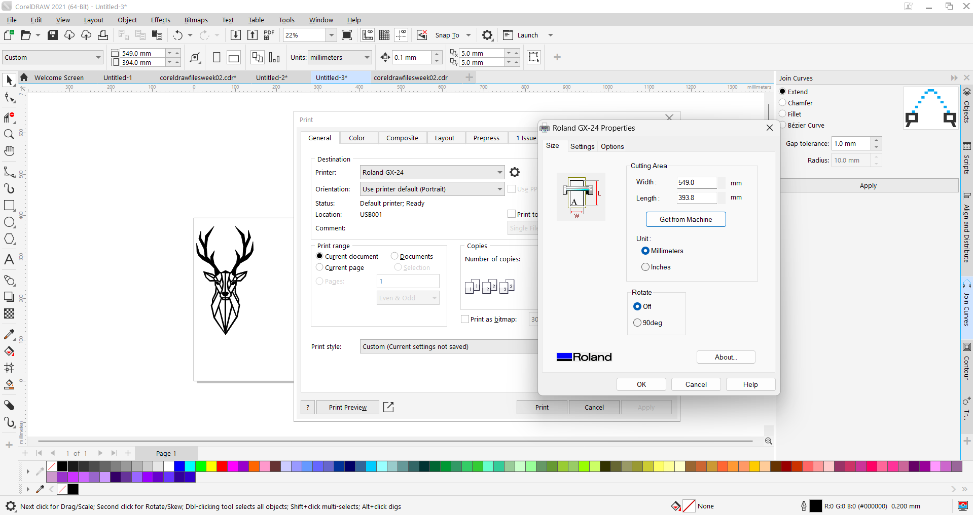
After that, I clicked to set the size from the machine and then pressed OK, then I pressed apply and print
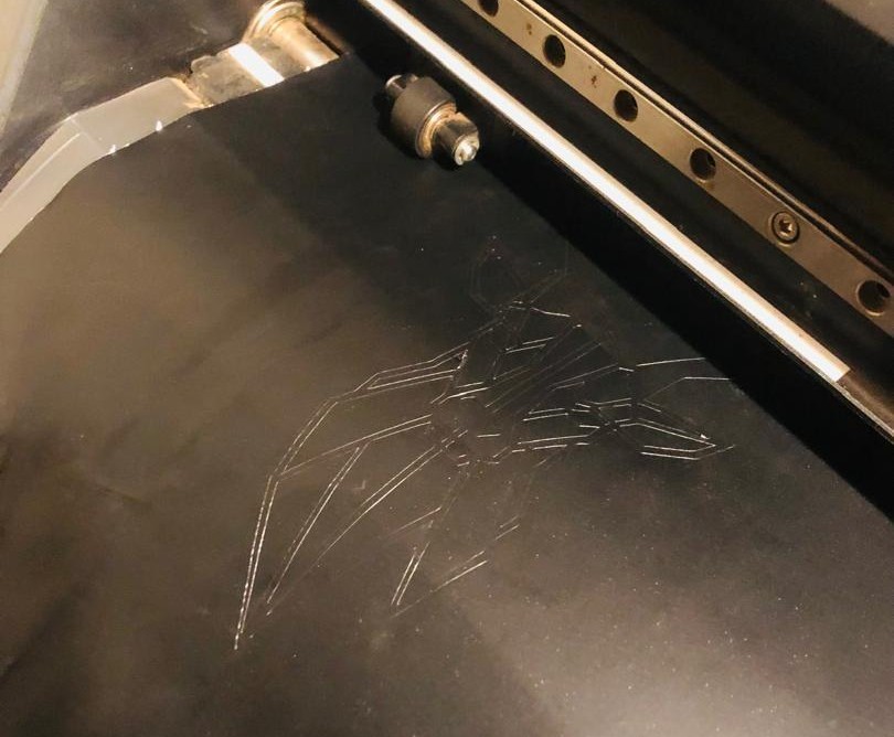
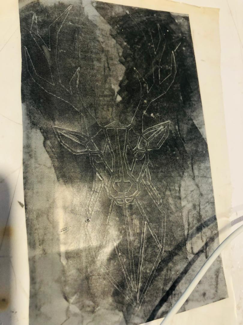
The machine is currently plotting the design
After i got the final result
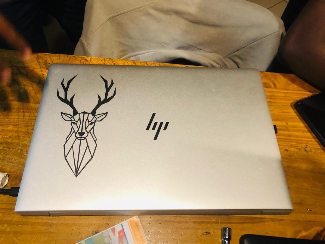
I used transfer paper and removed the unwanted parts, leaving only the design
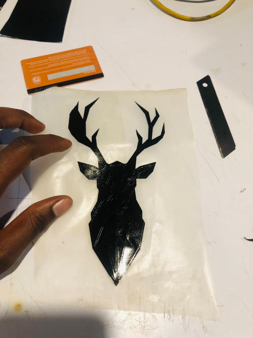
After that, i pasted it on my pc