This week's assignment was to design and produce a parametric construction kit using the laser cutter, and to create something using the vinyl cutter.
Group Assignment
Check here the group assignment of this week to more information about machine testing and safety.
During this assignment I learned the basics of laser cutting technology and how to safely operate the machines. Our lab has three CAMFive CO2 laser cutters, each with different work areas but all with 100W of power. I learned about the key parameters that affect the quality of a cut, such as power, speed, focus, and kerf, and how adjusting them can make a big difference depending on the material.
Laser Cutter
The laser cutter is a computer-aided manufacturing (CAM) tool that uses a high-power coherent light beam to cut or engrave materials with extreme precision. The process is based on a CO2 tube that generates a laser, which is directed by mirrors toward a head with a focusing lens. This lens concentrates all the energy into a tiny point, melting or vaporizing the material in a controlled manner. The machine operates through coordinates sent from a computer, allowing the adjustment of power and speed parameters to achieve clean finishes.
Laser Cutter Components
Laser Resonator: The source where the laser beam is generated.
Beam Bender (Mirror): Reflects and redirects the laser beam toward the cutting head.
Laser Focusing Head: The structure that holds the lens and the nozzle where the laser exits.
Focusing Lens: Concentrates the laser beam into a very small point to achieve the power needed for cutting.
Laser Beam: The concentrated light beam that performs the work.
Laser Gas: A flow of air or gas that helps clear away burnt material and protects the lens.
Nozzle: The tip through which the laser and gas exit toward the material.
Workpiece: The material that you are cutting or engraving.
Focal Length: The exact distance between the lens and the finest point of the beam on the material.
Fig 1. Laser Cutter Components
📏
Tip: To calibrate the laser head is important to maintain a distance of 5 mm between the Nozzle and the material. This distance is crucial to ensure optimal cutting performance.
Machine used
CFL-CMA1390T
Work area: 1.30 x 0.90 meters
Work Table: Honeycomb
Cutting Speed: 0-36,000 (min,mm)
Engraving Speed: 0-64,000 (min,mm)
Power: 100 Watts
Cutting Thickness: 0-25 mm
Laser Cutting controls
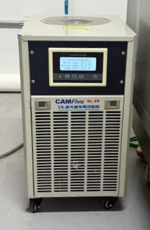
Turn on chiller
First thing to do before starting the laser cutting process is to turn on the chiller system.
Chiller System
The chiller system cools the laser head and maintains a stable temperature for consistent performance.
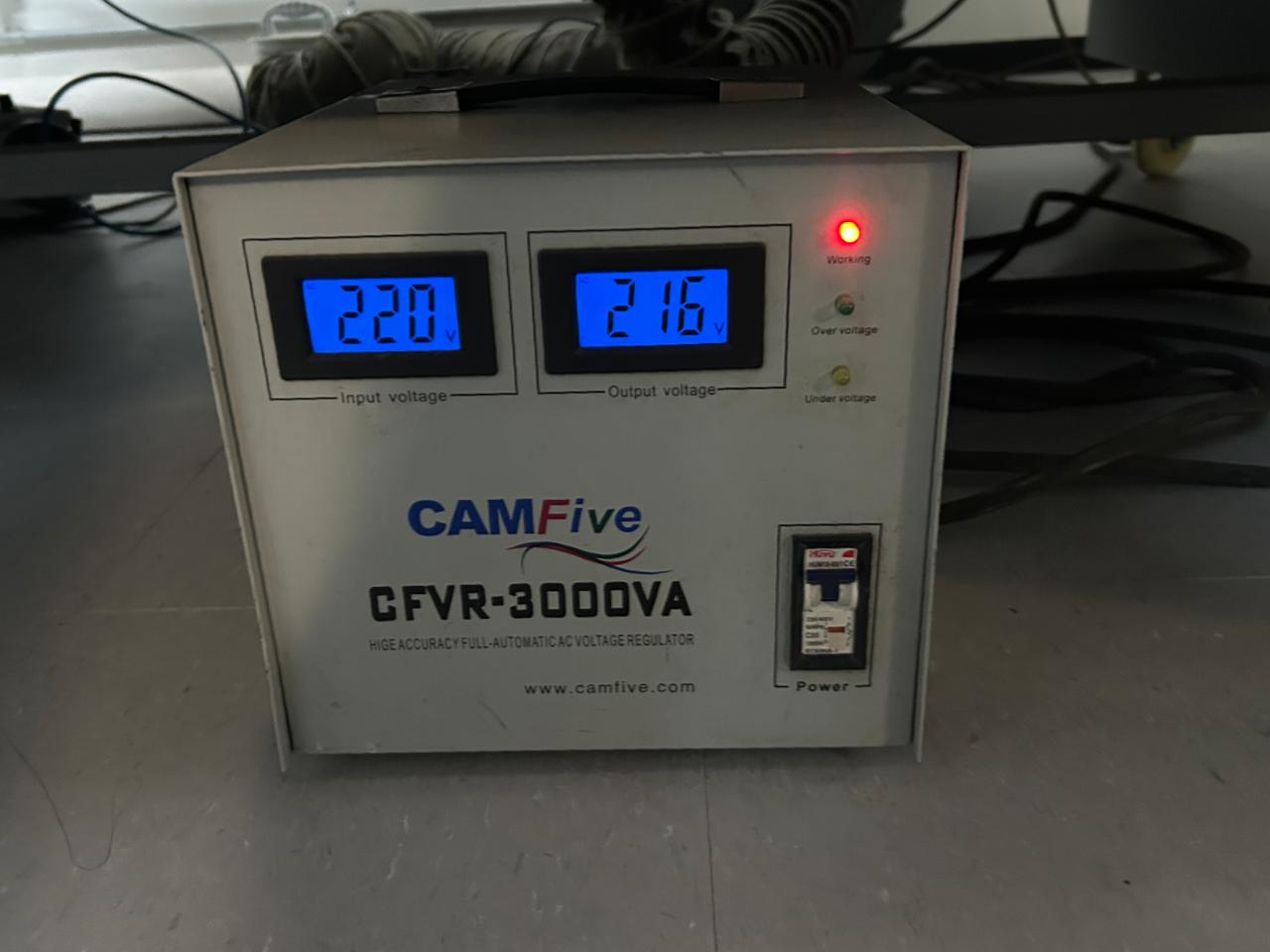
Voltage Regulator
The second step is to turn on the voltage regulator. The voltage regulator ensures stable power supply to the laser system, preventing fluctuations that could affect performance.
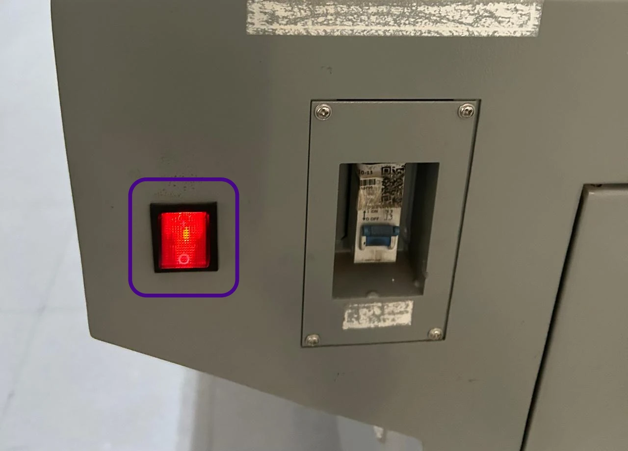
Turn on Laser Button
After turning on the chiller and voltage regulator, turn on the main laser button to power up the laser system.
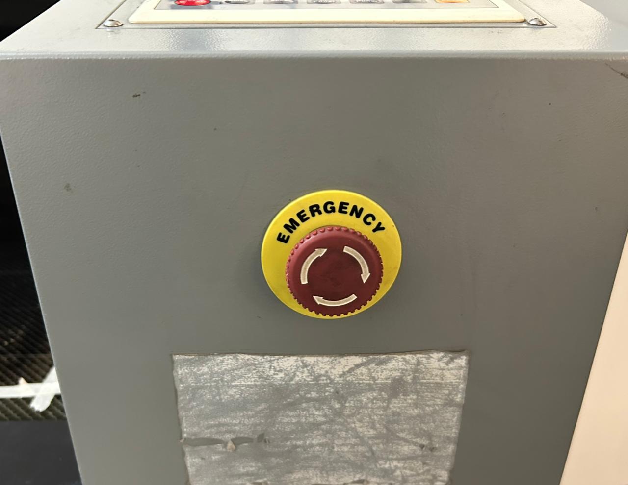
Emergency Stop Button
To start release the emergency stop button. Always be aware of the emergency stop button location. In case of an emergency, press the emergency stop button immediately to shut down the laser system.
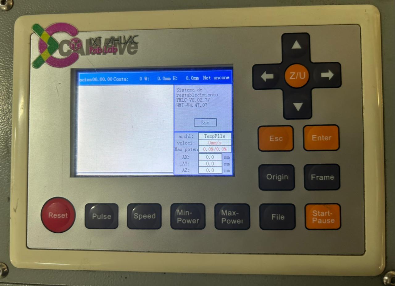
Control Panel
After inserting and turning the key the laser control panel activates, the control panel provides access to all system controls and settings. You can move the laser head using the arrow keys on the control panel.
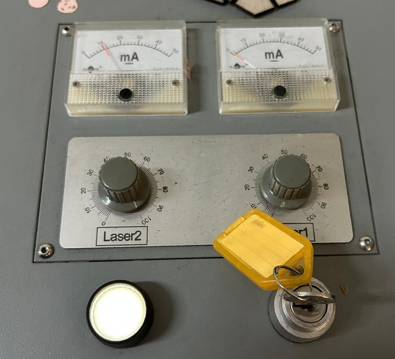
Laser Power Control
Once the laser system is powered on, on the top part of the control panel, you can adjust the laser power with the control knobs.
USB Memory
You can insert a USB memory device to load project files.
Insert the USB memory device into the USB port.
The file format must be .ou.
Press File button.
Use the arrow keys to navigate and select +Udisk.
Read Udisk
Use the arrow keys to select the desired file and press Copy to RAM
Cut
Return to the file menu by pressing the Esc button and press Enter to the file you want to cut.
Return to the main menu. To verify that the file fits in the laser workspace, press the Frame button.
Finally, increase the laser power and turn on the laser, then press the Start button to begin the cutting process.
To create a parametric construction kit, it is essential to use the Equations tool in SolidWorks. This tool allows us to define global variables and linked dimensions, ensuring that any change in a parameter automatically updates throughout the entire design. Here is a tutorial on how to use it:
First move the cursor to the SOLIDWORKS Logo.
Open the Equations dialog box by going to Tools > Equations
Fig 2. Tools menu
The Equations, Global Variables, and Dimensions dialog box will open. Here you can define and manage equations and global variables.
Fig 3. Equation Box
Define a global variable by giving first a name (e.g., "Width") and then a value (e.g., 100mm).
Fig 4. Defining a Global Variable
To delete a global variable, select with the right mouse button the variable and click Delete.
Fig 5. Deleting a Global Variable
To use a Global Variable in a dimension, simply type = and then the variable name in the dimension box. You can also use operations by typing = "Variable1" - "Variable2".
Fig 6. Using a Global Variable in a Dimension
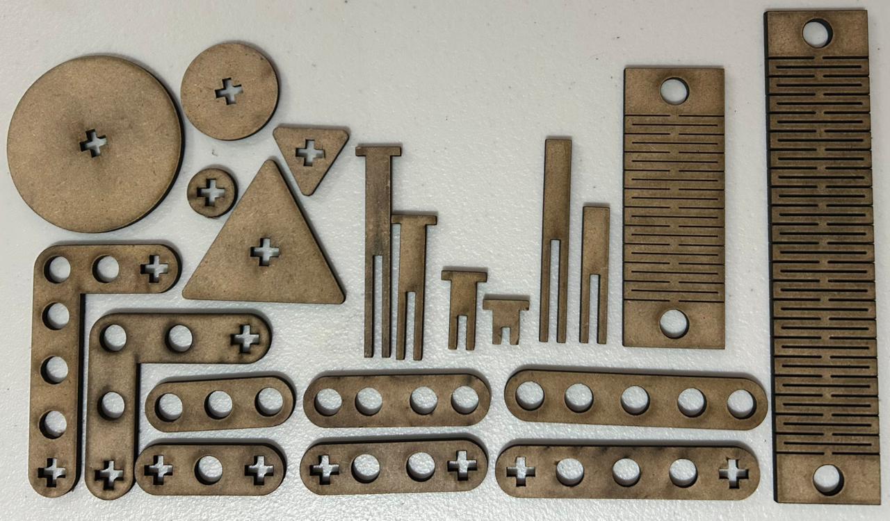
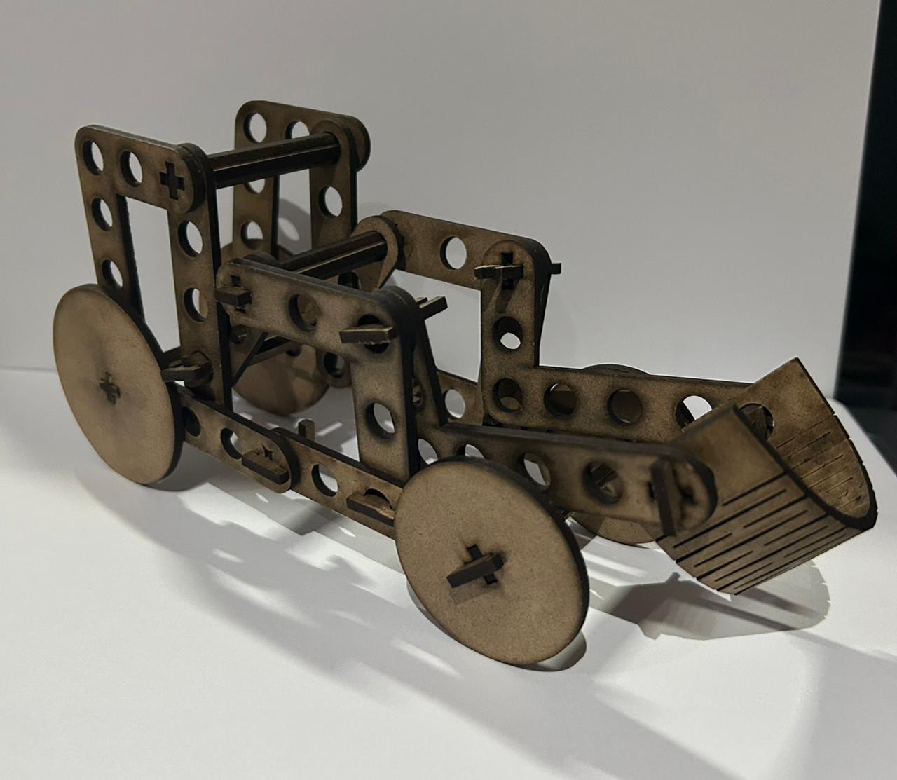
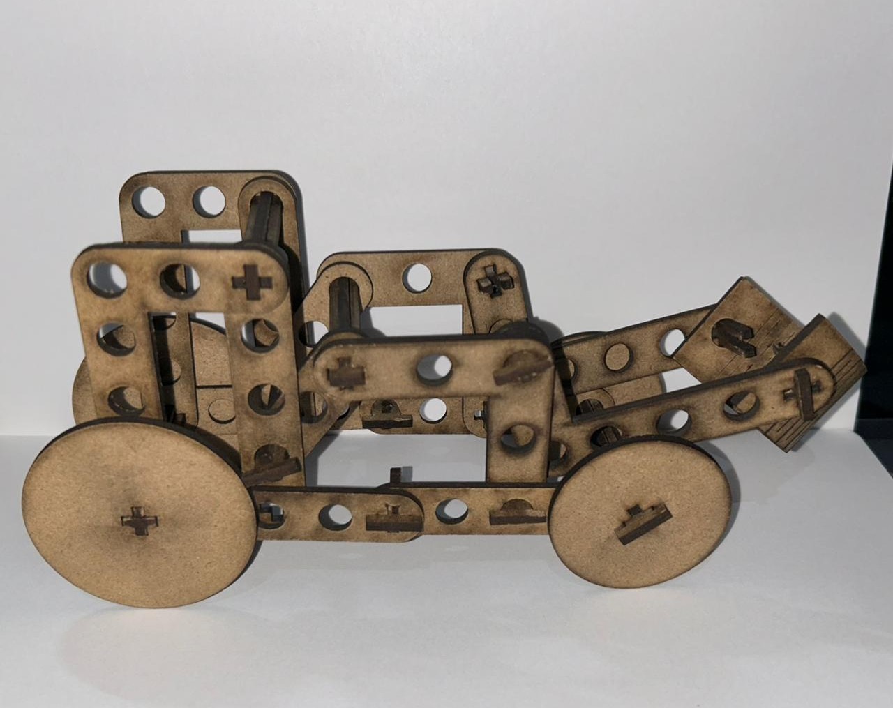
Parametric Kit
After create all the parts of the parametric kit, you need to exported the files as a .dxf file for the laser cutter program. Follow the next steps:
Save the parts that were previously created.
Open SolidWorks and create a Drawing file.
Fig 6. Drawing File
Select the sheet format and size.
Fig 7. Sheet Format and Size
Select Model View.
Fig 8. Model View
Insert the desired part using the Browse menu.
Fig 9. Importing a Part
Drop the part into the drawing sheet.
Make sure the part is in the scale you need by clicking on the drawing part.
Fig 10. Adjusting Scale of a Part
Save the document as .DXF format.
Fig 11. DXF Format
Smart Carve
Smart Carve
SmartCarve is the control software used with our CAMFive CO2 laser cutters. It allows you to import design files in DXF format, organize cutting layers by priority, and adjust parameters such as power and speed before sending the job to the machine.
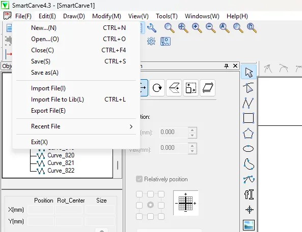
Import
Save your design file in .DXF format before opening SmartCarve.
Open SmartCarve and go to the top menu.
Select File > Import File and choose your design.
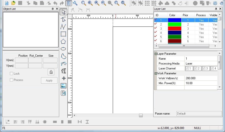
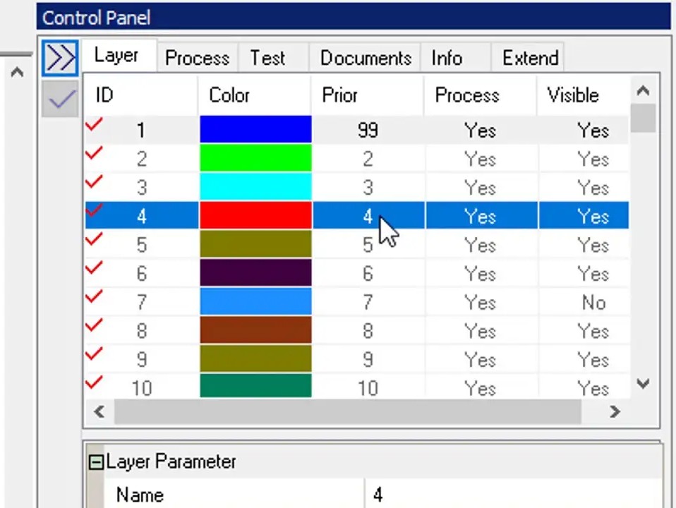
Setting Parameters
On the main interface, the control panel is located on the right side, where you can set the power and speed for each layer. By assigning different colors to different parts of your design, you can apply specific settings to each one independently.
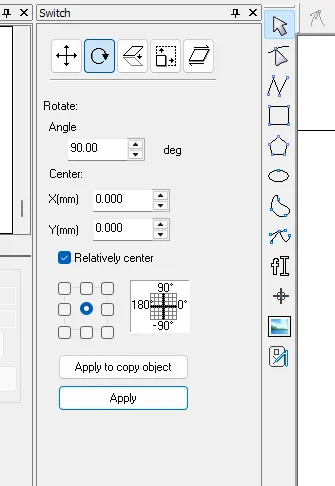
Switch
On the left side menu you will find the Switch panel, where you can move, rotate, scale, mirror and apply other configuration options to your design.
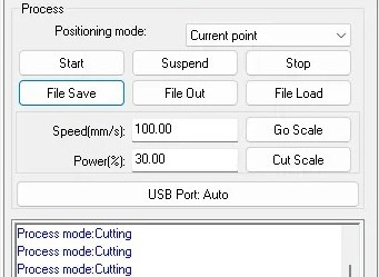
Export
To export your file in .oud format, which is the format used by the laser cutter, go to the lower right section of the screen, click on File Save, select your desired location, and your file will be ready to load into the machine.
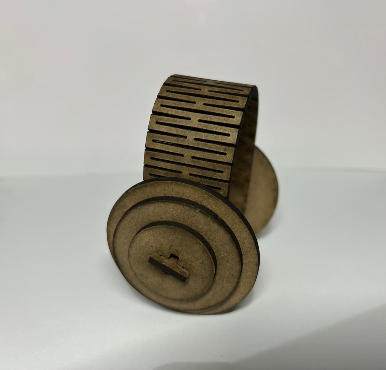
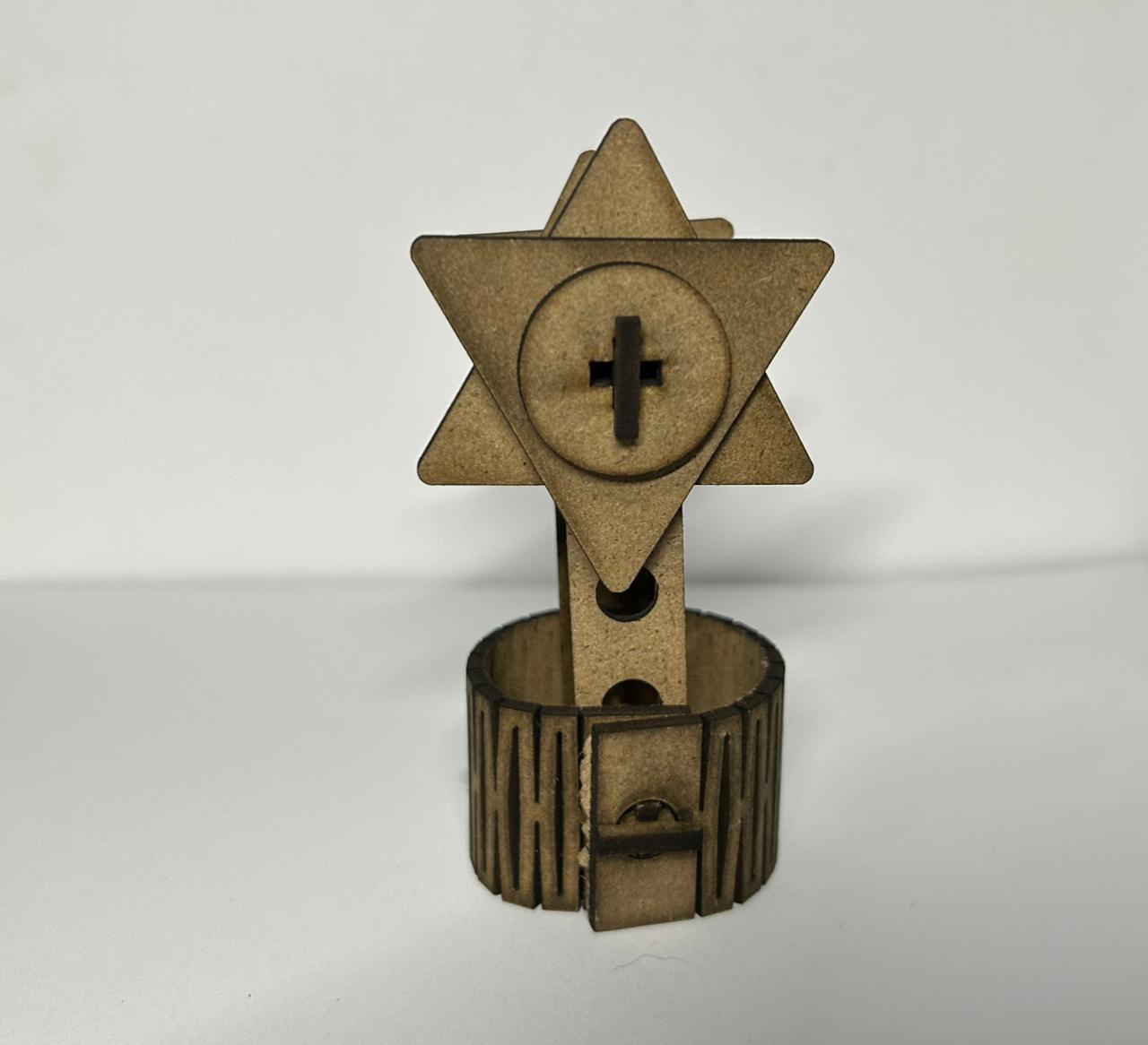
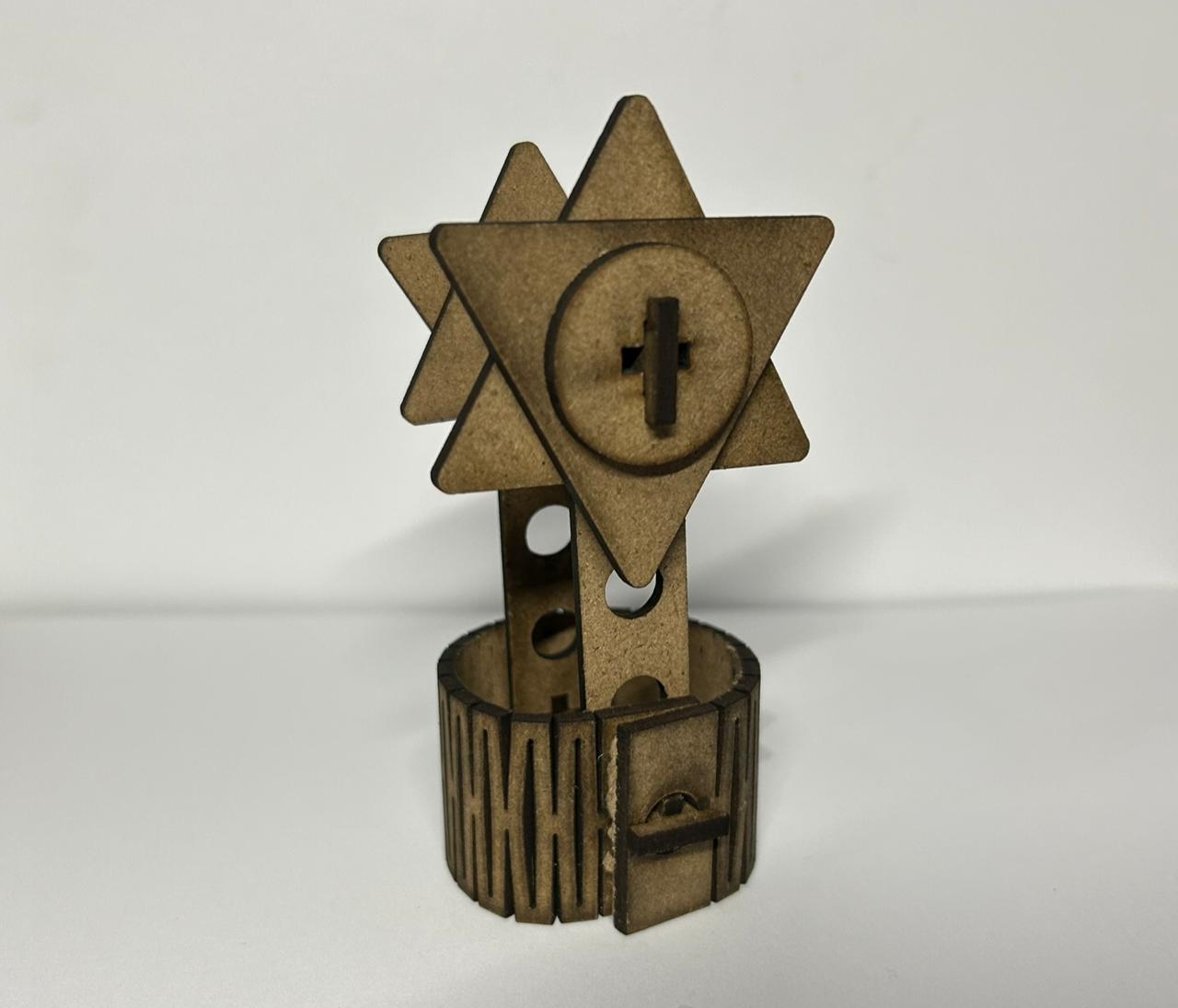
This circular piece was designed with a multifunctional approach. Its geometry facilitates mobility and rotation into various mechanical assemblies. To make the circle parametric, I set variables to modify the diameter, thickness, kerf, and the large of the cross in the middle. By simply modifying the values in the global parameters, the entire design is updated.
Line
This piece serves as the structural link of the modular kit. It features regularly spaced slots that act as universal attachment points, allowing other modules to be easily connected. This part is a simple line that can be parametrically modified in length and thickness. Also the circles and the cross sections of the line are parametrically defined, allowing for easy modification of the entire design.
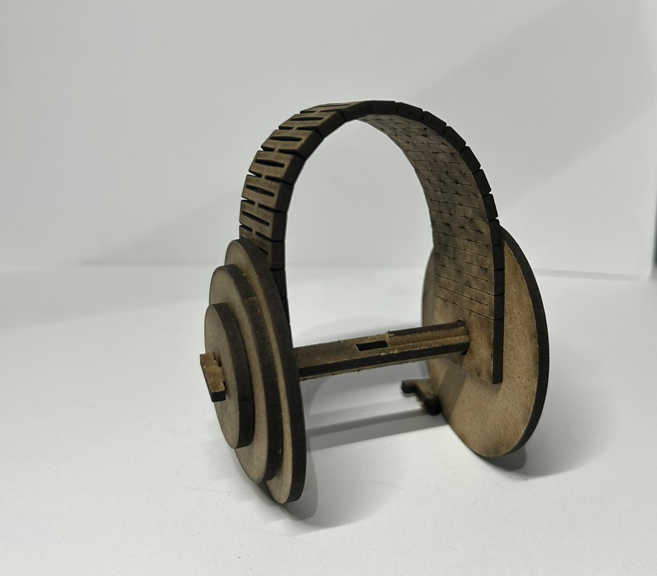
Flexible Piece
This flexible piece is designed to allow for variable degrees of freedom in the modular kit. For the flexible piece, to define the variables I used the Fab Lab Puebla 2025 Global Page parameters. I only modified the thickness, kerf and the angle of the flexible piece.
L Piece
This piece is a corner piece that allows for 90-degree connections in the modular kit. It is designed to be parametrically modified in terms of thickness, kerf and long.
Triangle
This triangle piece is designed to add creativity and variety to the modular kit. For the triangle piece, I defined the variables for thickness, kerf, long of the cross and the diameter of the circle in the center.
Cross union
This cross union piece is designed to connect multiple modules. It is parametrically defined with variables for thickness, kerf, and the size.
The vinyl cutter is a computer-controlled machine that uses a sharp blade to cut shapes and designs from sheets of vinyl material.
For the vinyl cutter assignment, I use a Kuromi design that i processed first in Inkscape to create the vector file needed for the vinyl cutter.
How to Vectorize an Image
Open Inkscape and import your image: File > Import.
Select the image by clicking on it.
Go to Path > Trace Bitmap.
Adjust the threshold until you get a clean result in the preview.
Click OK and a vector will be placed on top of your original image.
Move the vector aside and delete the original bitmap underneath.
Adjust the image size to the desired dimensions.
Save your file as .svg.
It is important to vectorize the image that you are going to use and save as svg format for the vinyl cutter to follow the accurate outlines.
Kuromi Vector
Machine used
Brother ScanNCut Mini Plotter
Type: Desktop Cutting Plotter
Scanner Resolution: 300 DPI
Special Feature: PC-Free operation
Tools: Cutting blade and drawing pens
Max Material Thickness: Up to 3.0 mm
Vinyl Cutter Controls
Start Up Process
First, adhered the vinyl material to the cutting mat.
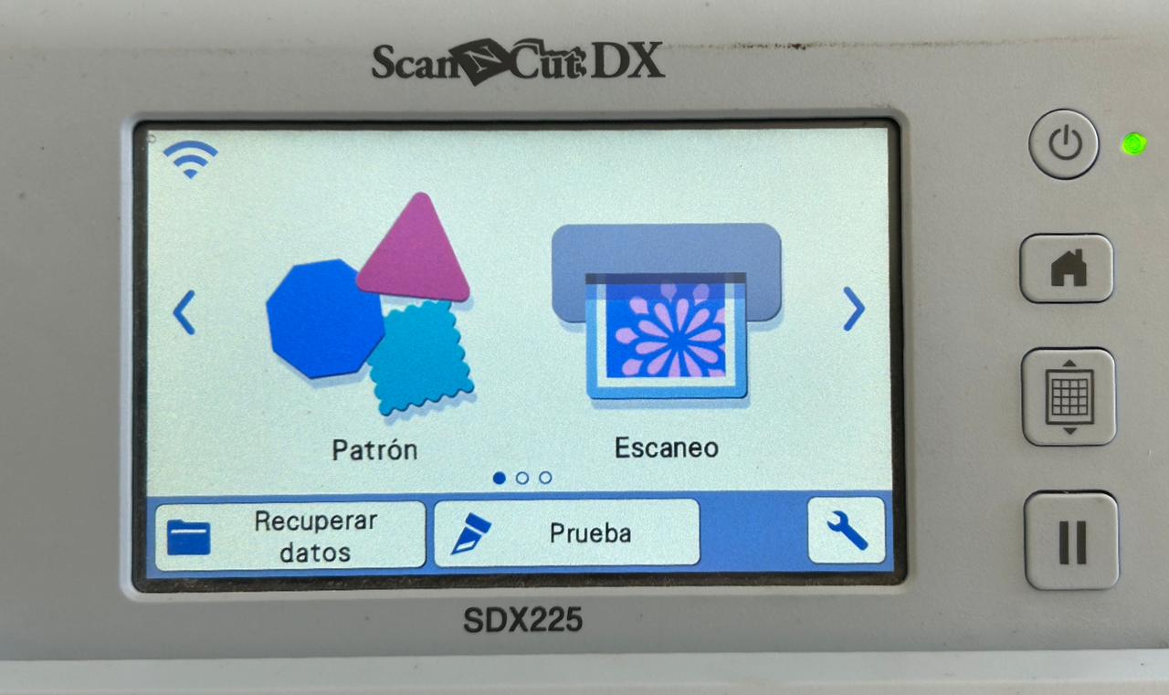
Turn on the machine. You will see the main menu.
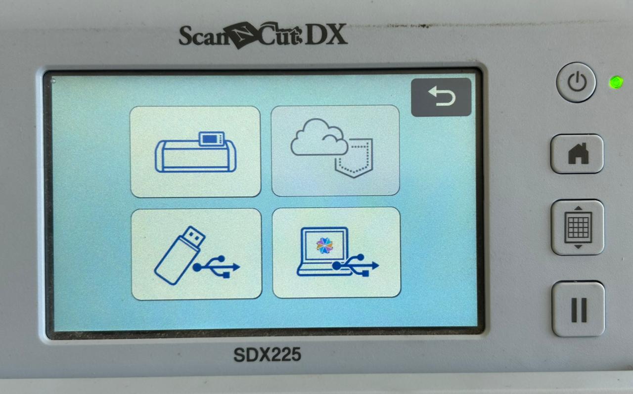
File Selection
To select the file you want to cut, you can use some import options such as USB driver or network connection.
Scanning
The button in the middle allows you to scan the cutting mat, which helps to ensure accurate alignment of your design.
Once you positioned the design correctly, press OK
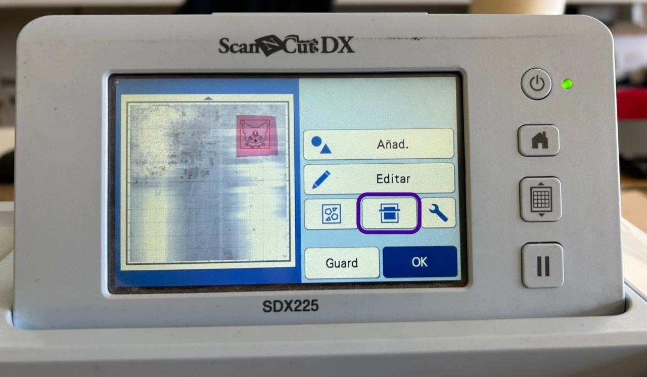
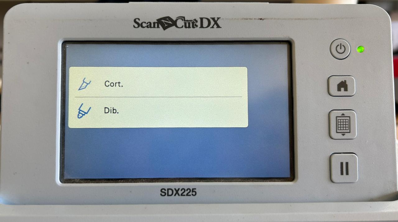
Tool Selection
Select the appropriate tool you need. The tool selection menu allows you to choose between two tools such as a cutting blade (Cut) or drawing pen (Draw).
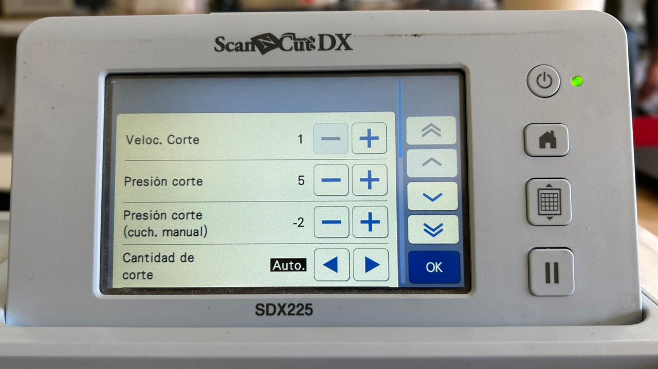
Settings Parameters
In this menu by clicking the wrench icon you can adjust cutting settings such as cutting speed, pressure, and blade depth.
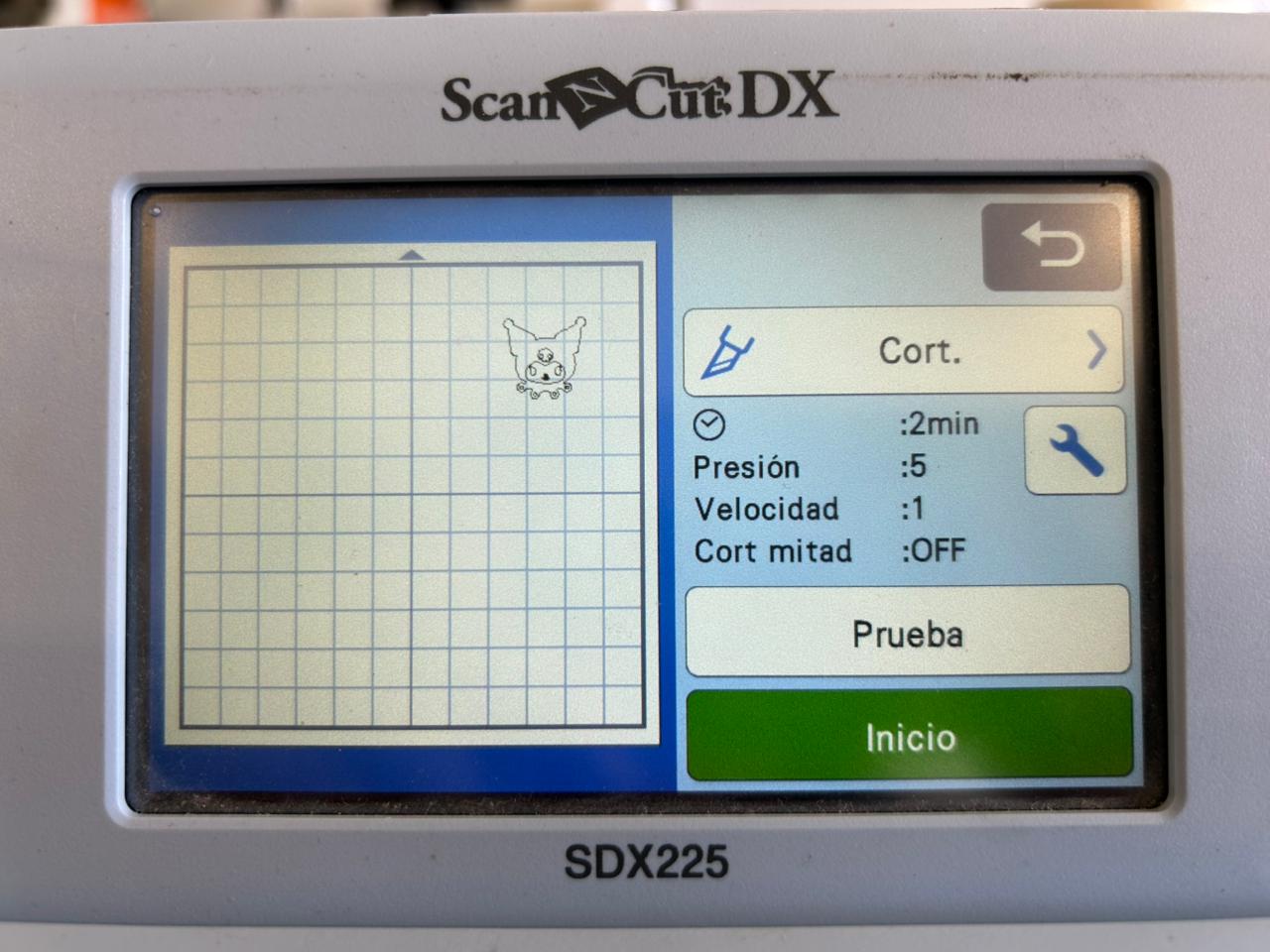
Settings
These are the settings that i used for textile vinyl:
Cutting speed: 1
Cutting pressure: 5
After adjusting the settings press OK, now you can proceed to cut your design by pressing the Start button. Always make sure to monitor the cutting process to ensure everything is going smoothly.
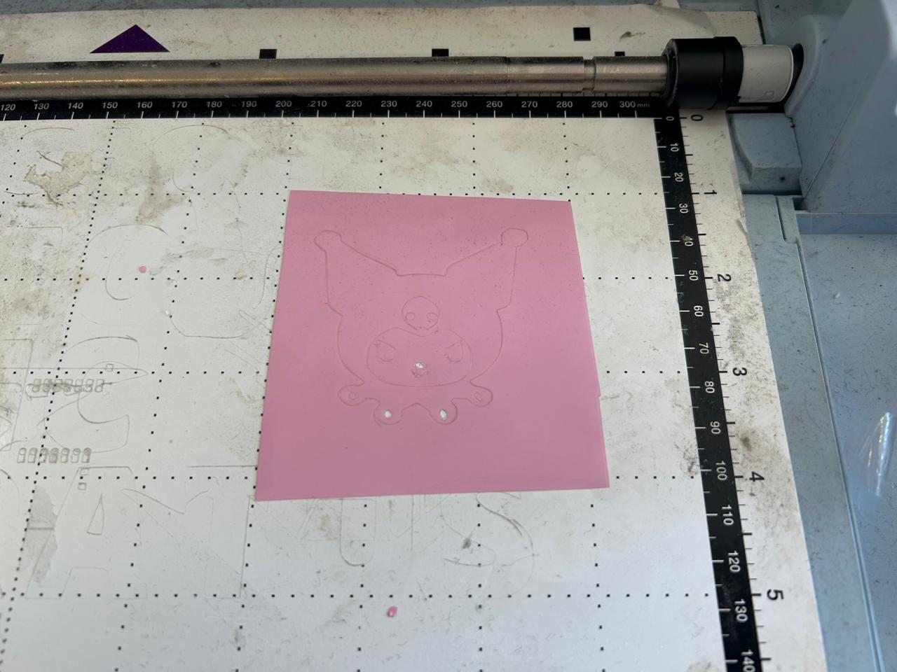
For my vinyl cutting project, I decided to use textile vinyl material. After cutting the design, I used a heat press machine to transfer the vinyl onto my lab coat. The result was a cute Kuromi design on the sleeve, which I really liked.
Heat Press Machine
Transfer paper
To safely remove and transport the vinyl cut, apply a piece of transfer tape over the design. This ensures that all components stay in their correct position and allows for a precise application onto the final surface.
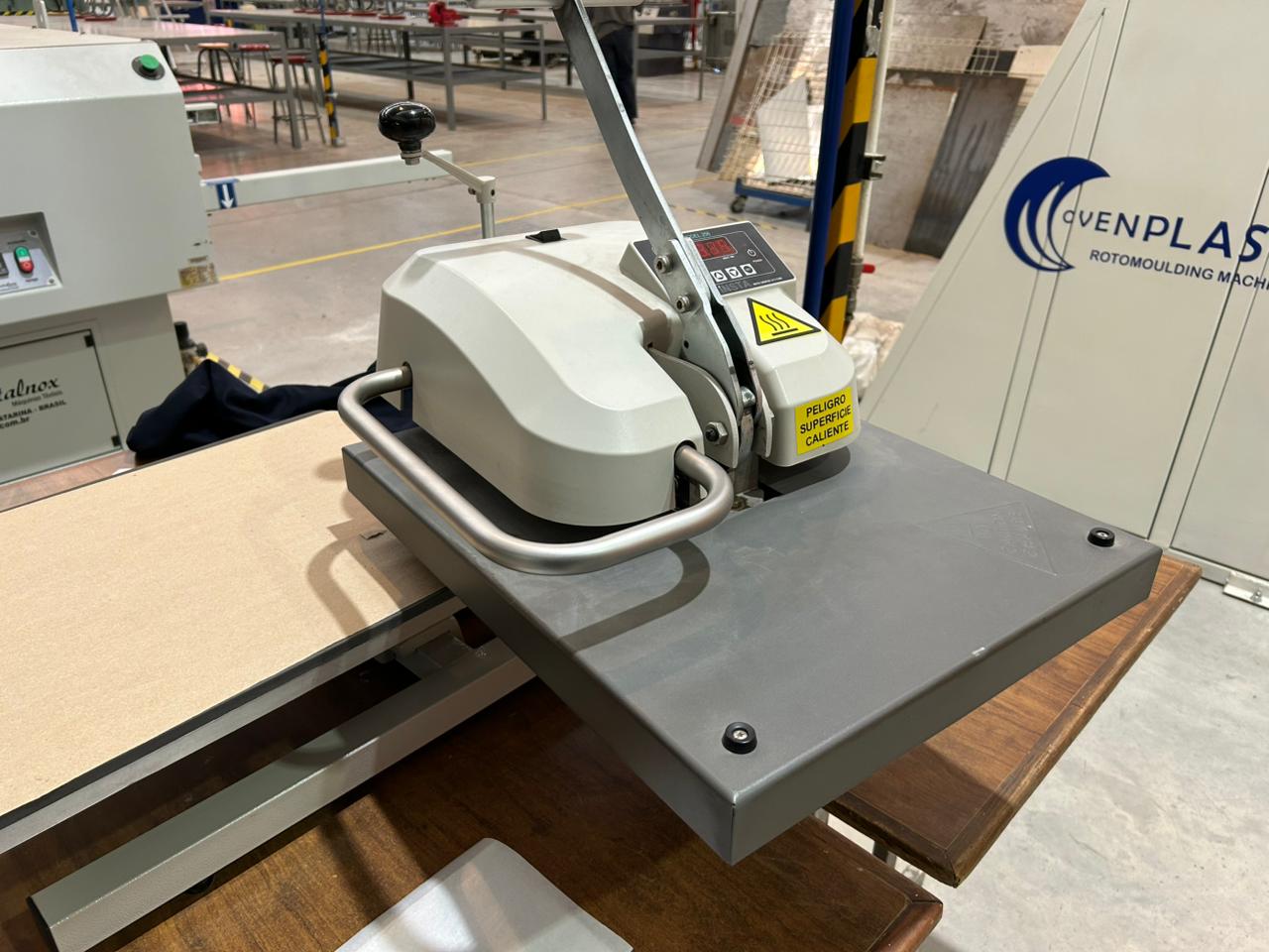
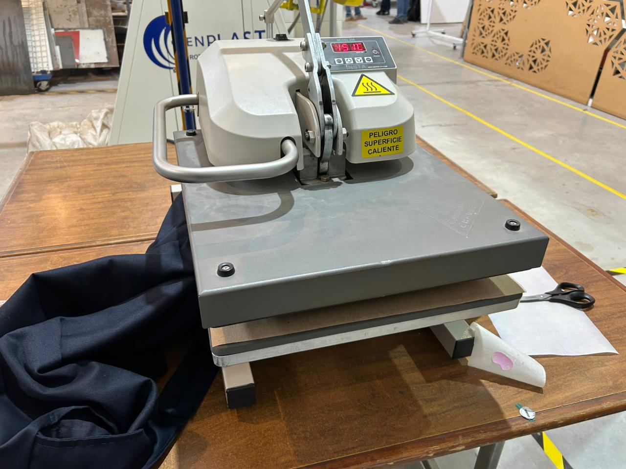
Heat Press Machine
This is the heat press machine I used, the first step is to turn it on.
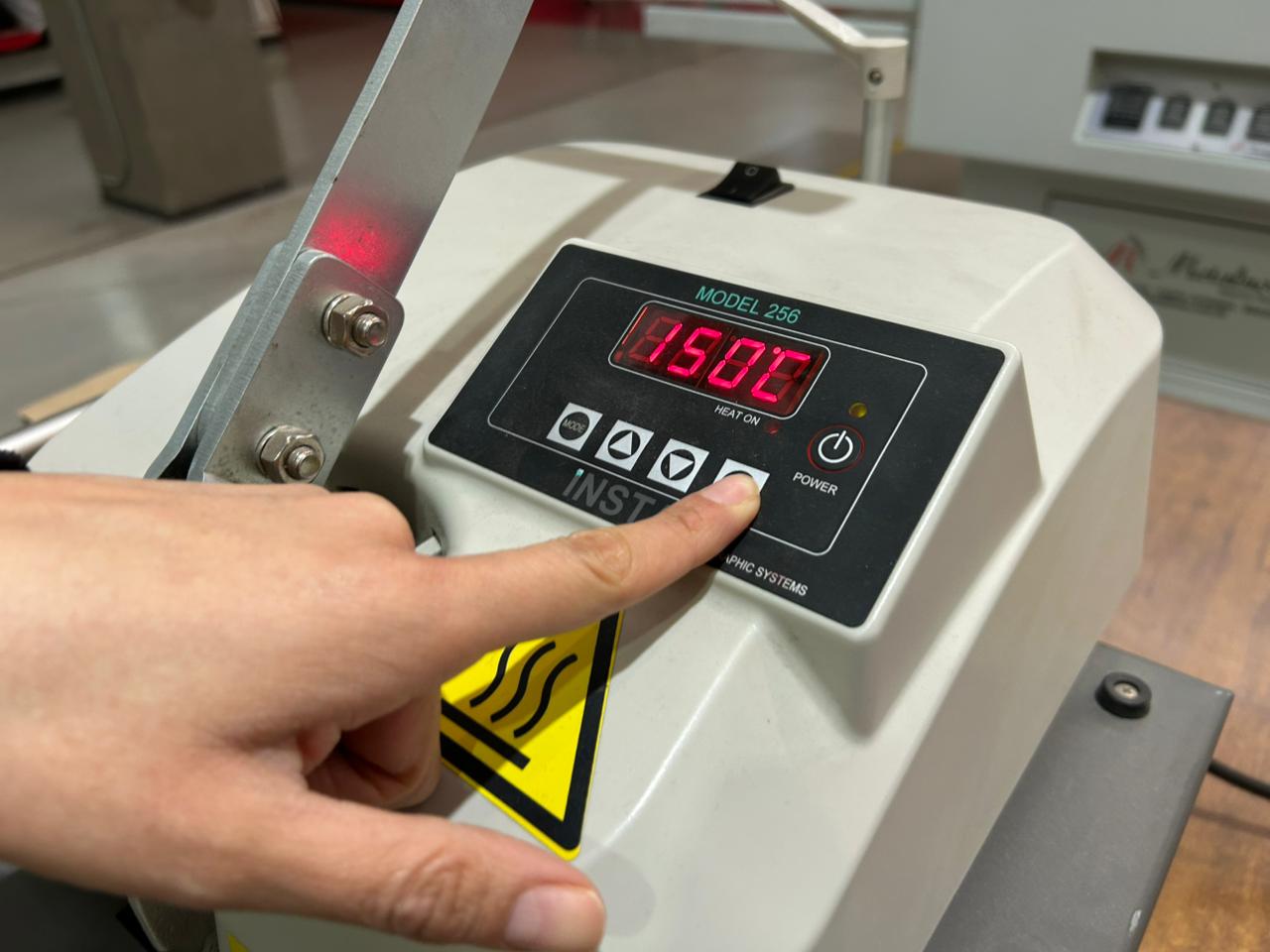
Heat calibration
Then you need to calibrate the heat temperature. In the Heat Mode you need to press the Set button and the arrow keys at the same time to adjust the temperature.
Temperature: 120°C
Tip: Use clothes made of at least 80% polyester
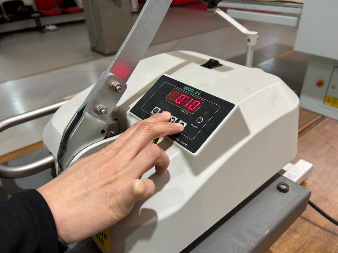
Time calibration
You also need to calibrate the time. In the Time Mode press the Set button and the arrow keys to adjust the time.
Time: 10 seconds
Set up
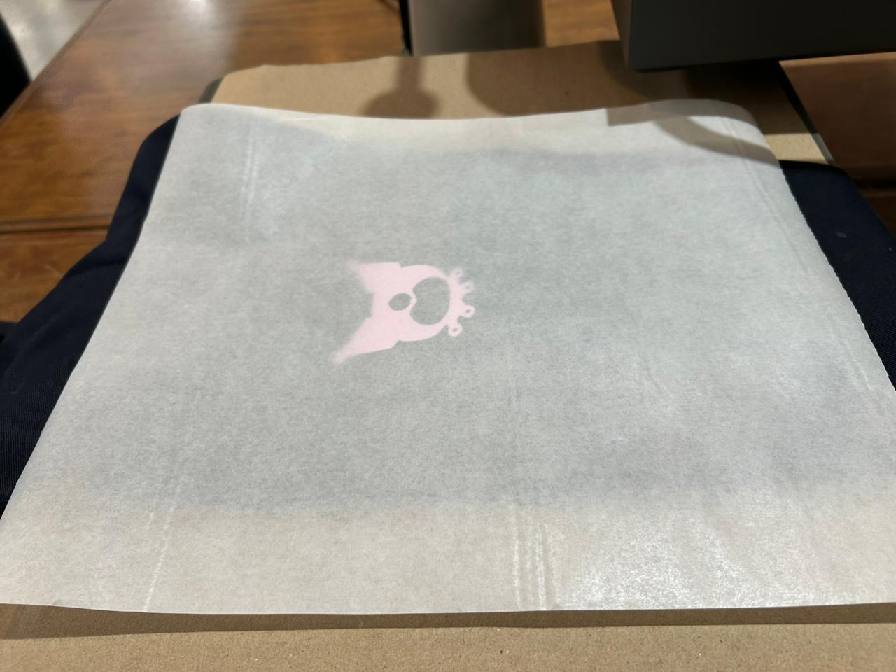
Place your garment with your design on the heat press machine and make sure it is properly aligned. Use wax paper to protect your design and your garment from the heat.
Start
Once everything is set up, move the heat press machine to the accurate position and lower the lever until you hear a click. The start process will begin automatically.
After the time is up, release the safety lock and lift the lever. Carefully remove your garment, let it cool down before removing the protection tape to reveal your final design.
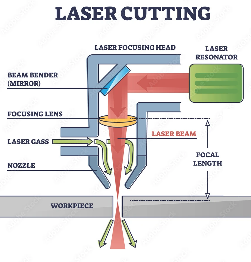 Fig 1. Laser Cutter Components
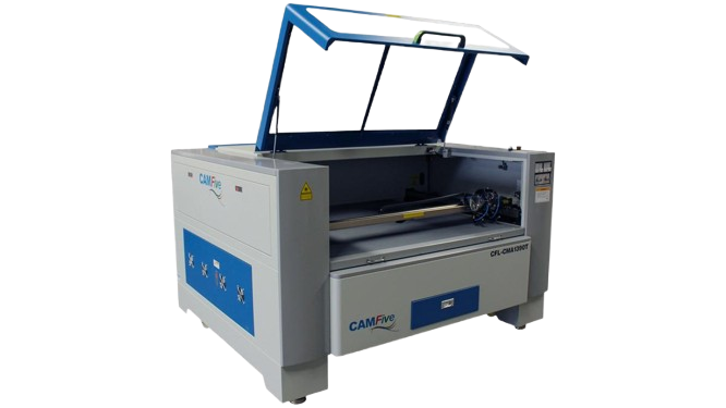
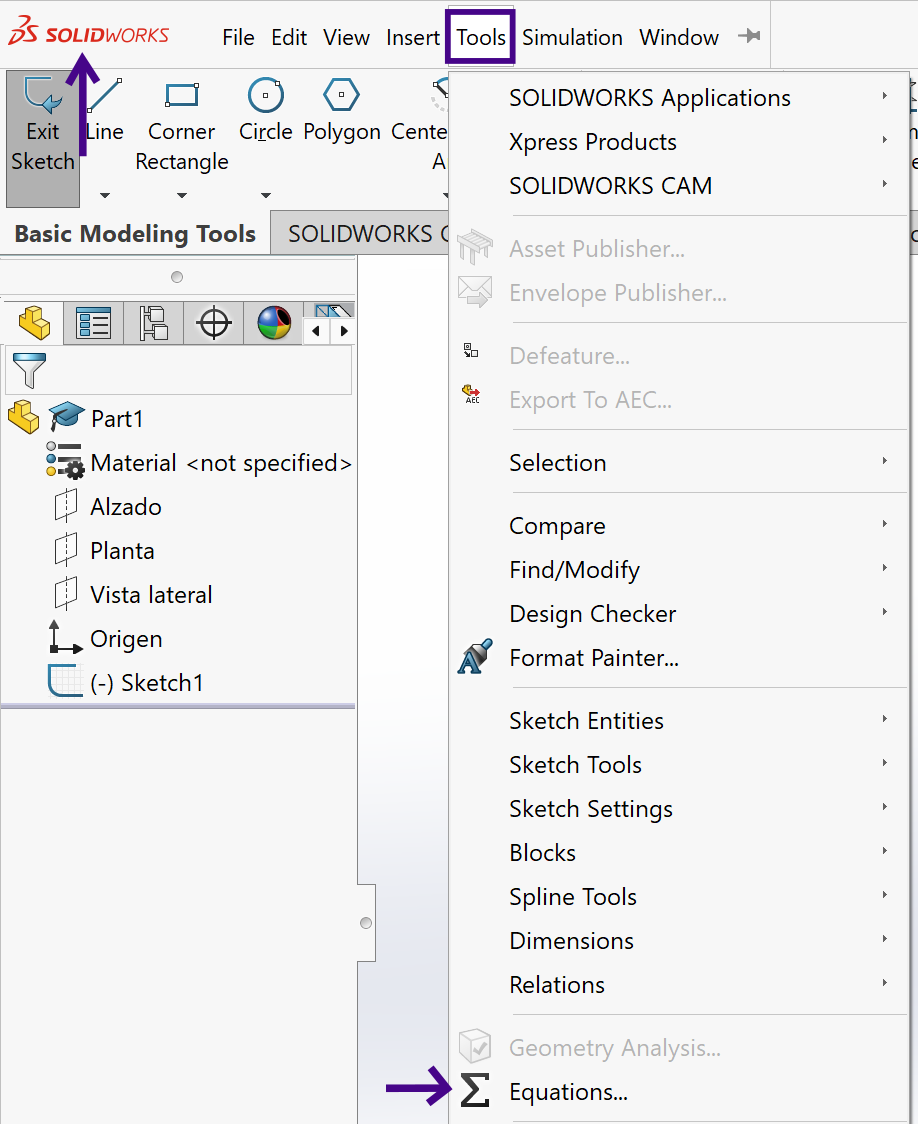 Fig 2. Tools menu
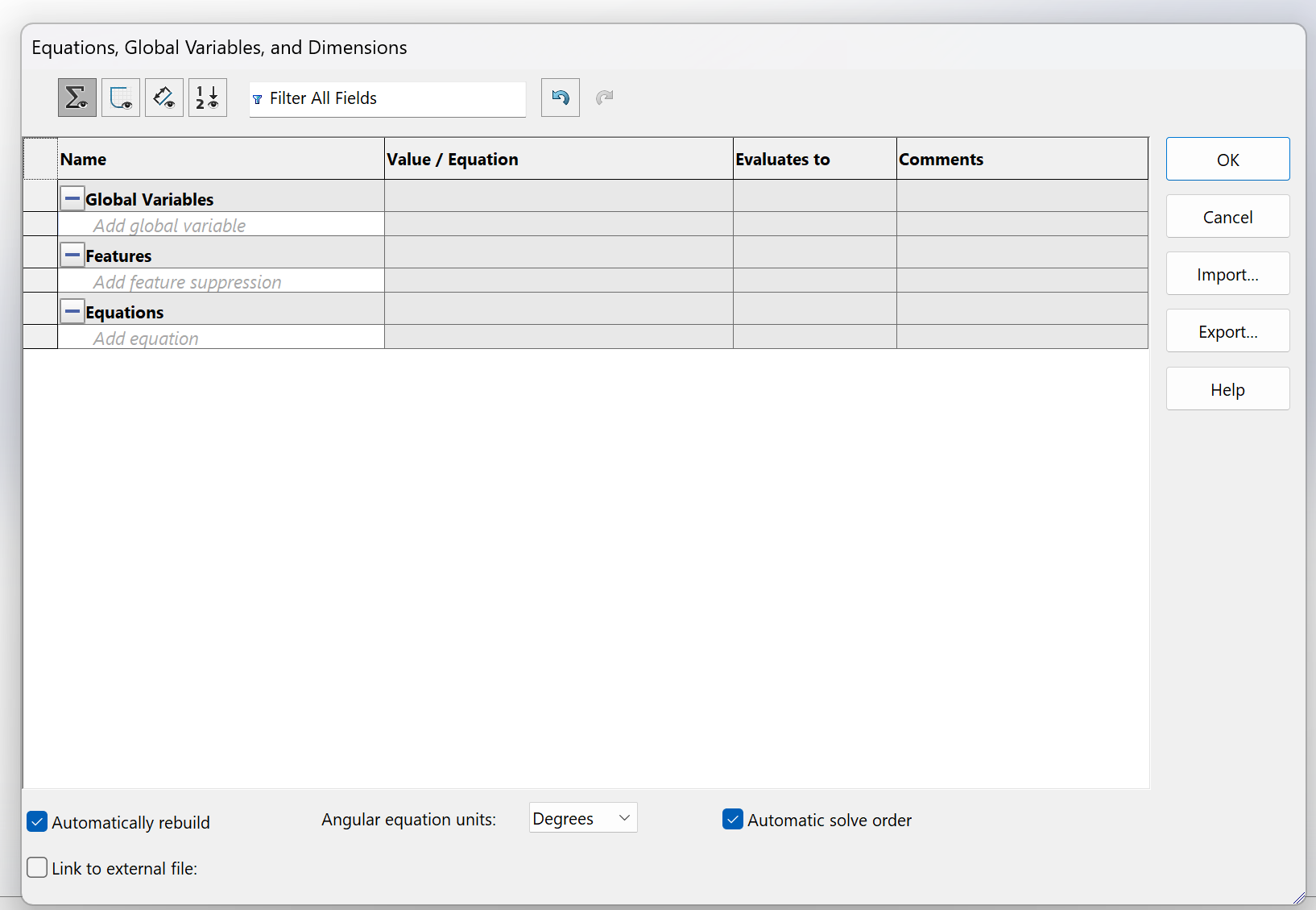 Fig 3. Equation Box
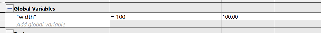 Fig 4. Defining a Global Variable
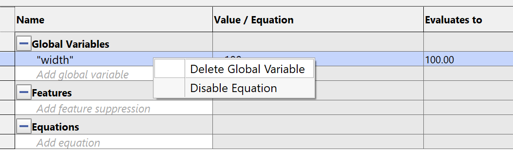 Fig 5. Deleting a Global Variable
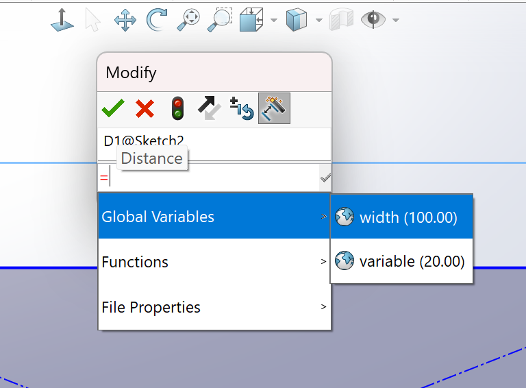 Fig 6. Using a Global Variable in a Dimension
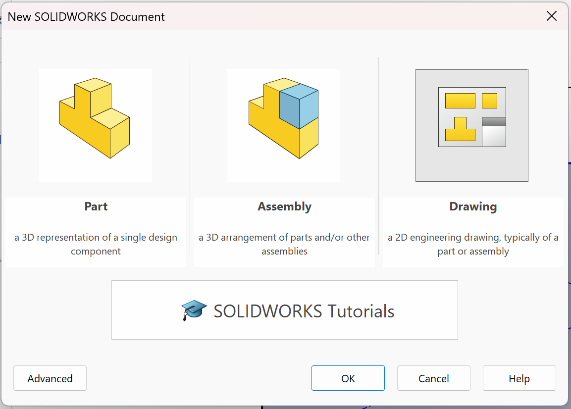 Fig 6. Drawing File
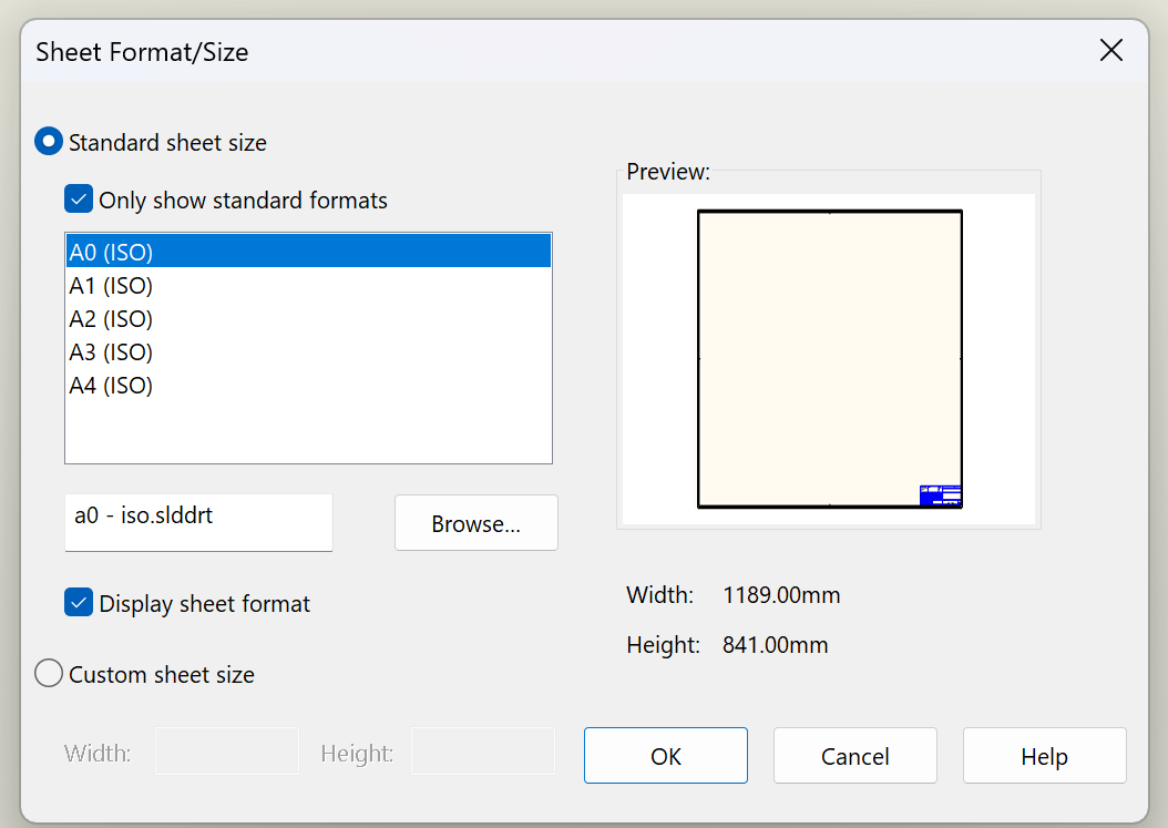 Fig 7. Sheet Format and Size
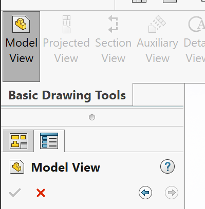 Fig 8. Model View
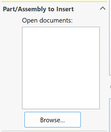 Fig 9. Importing a Part
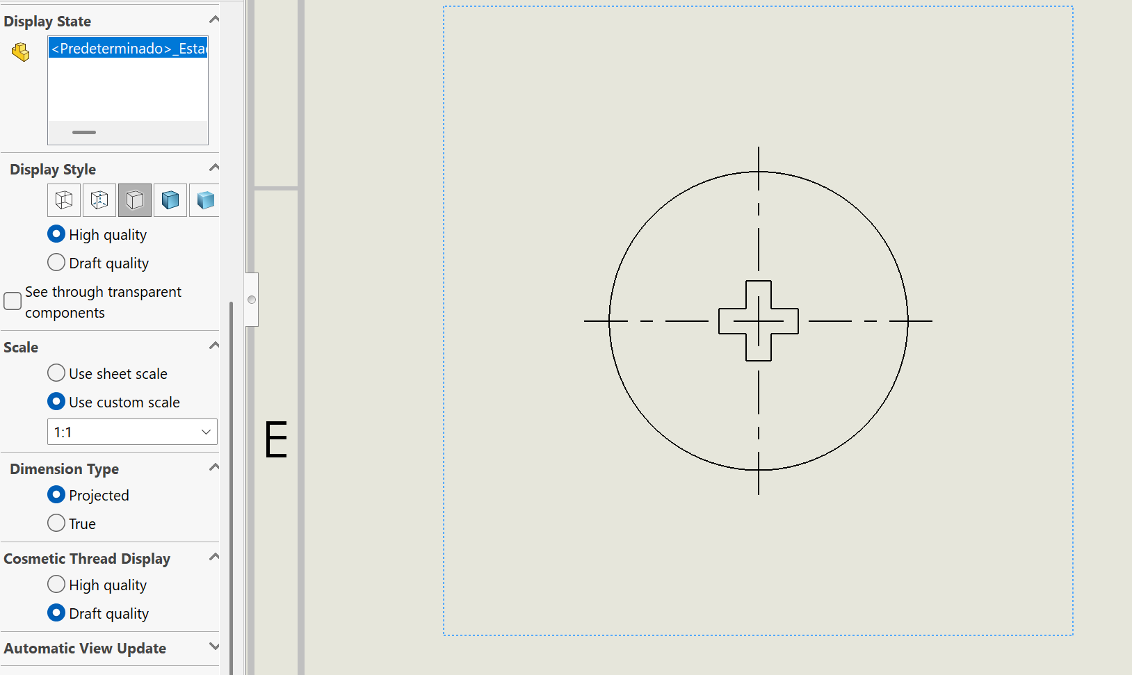 Fig 10. Adjusting Scale of a Part
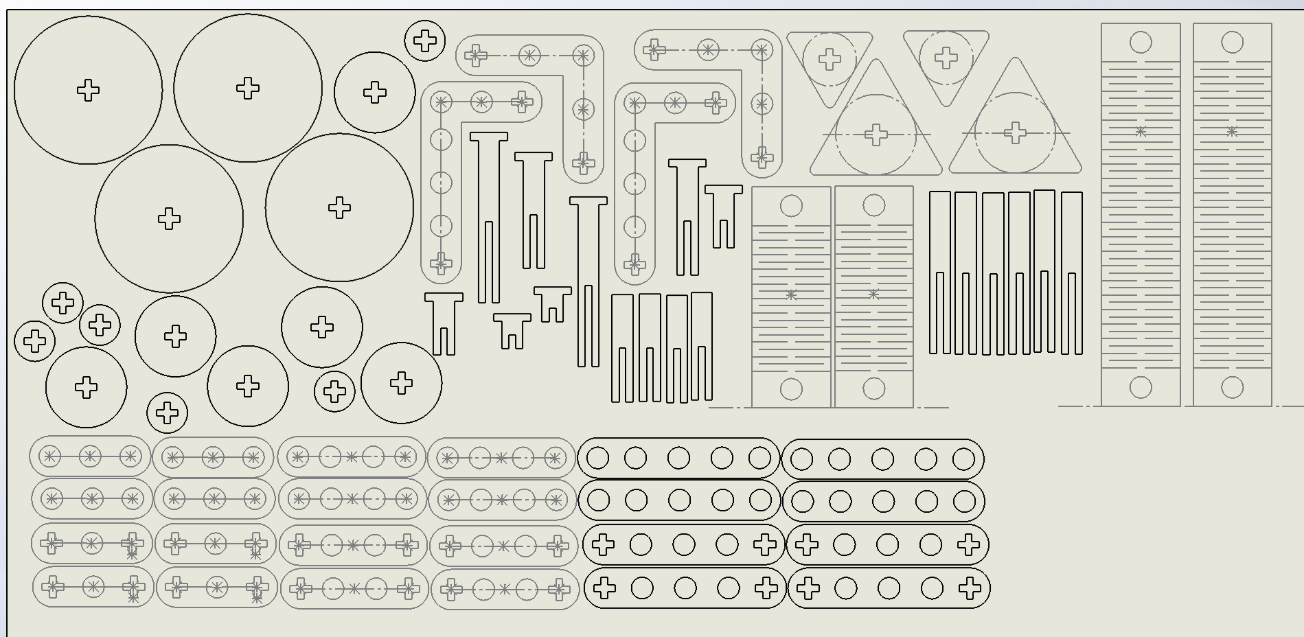 Fig 11. DXF Format


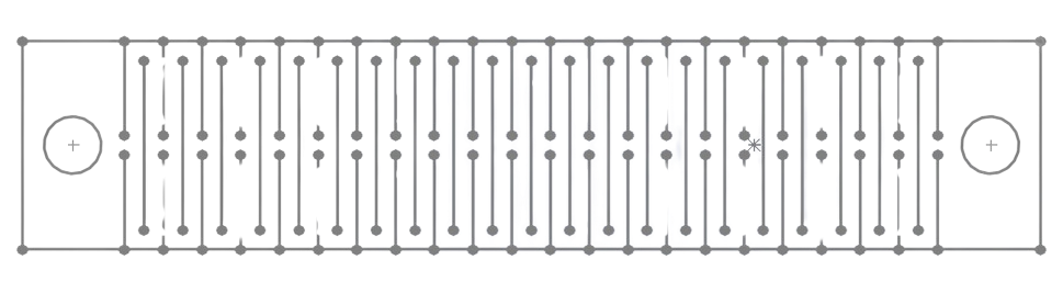
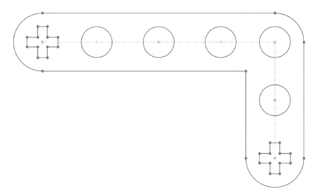
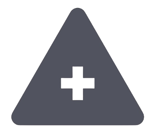

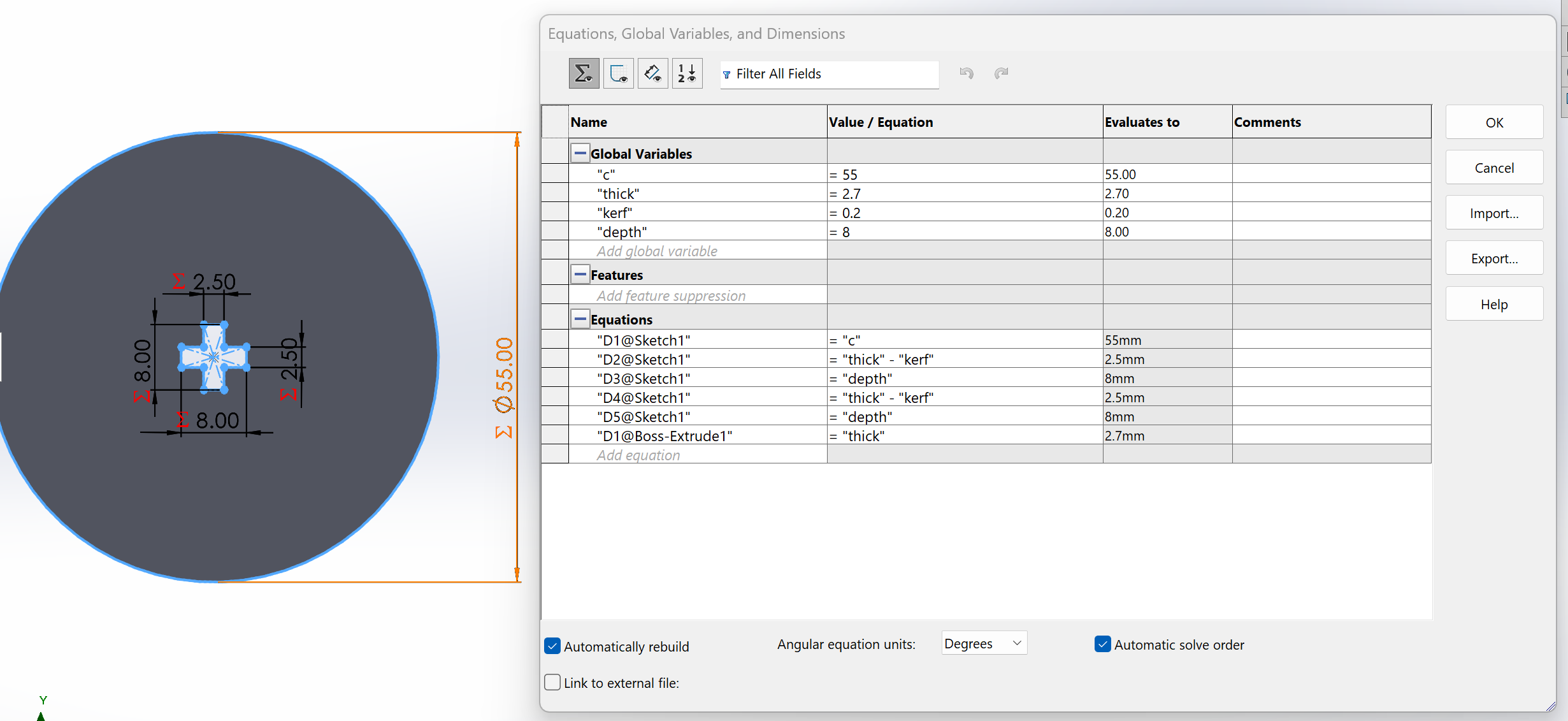
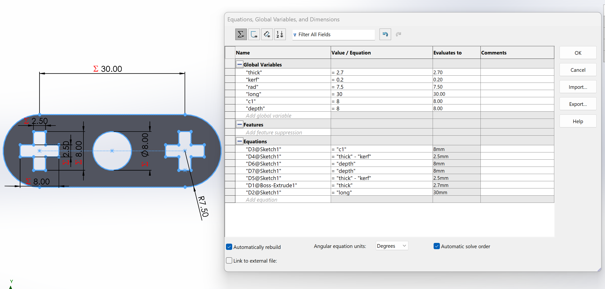
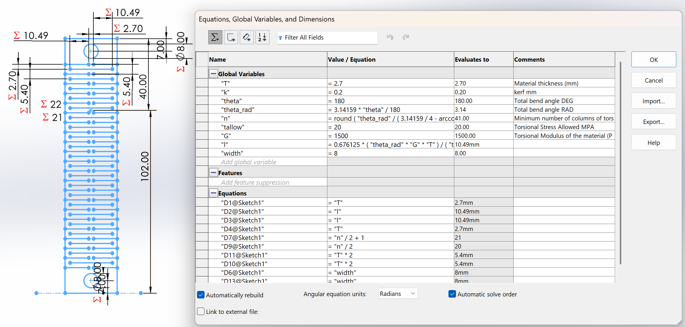
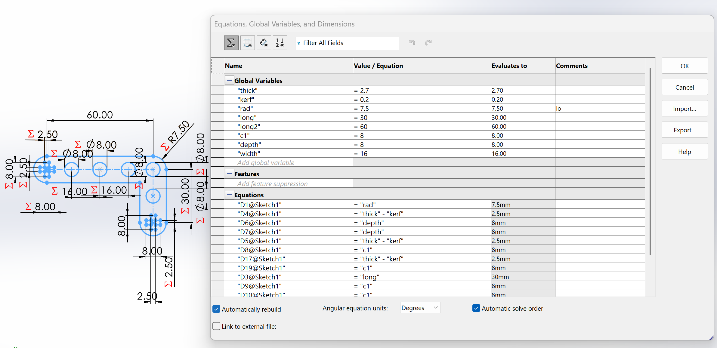
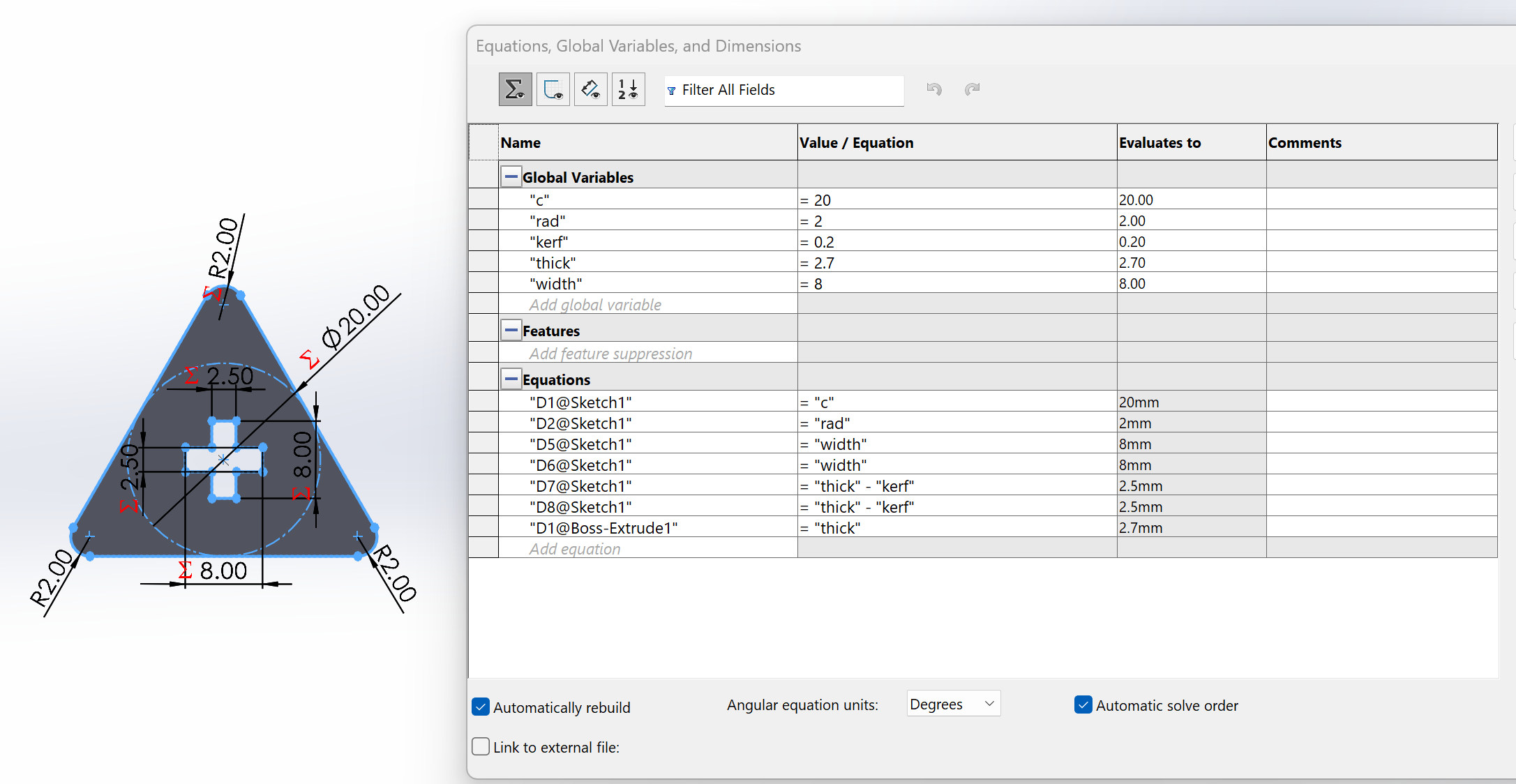
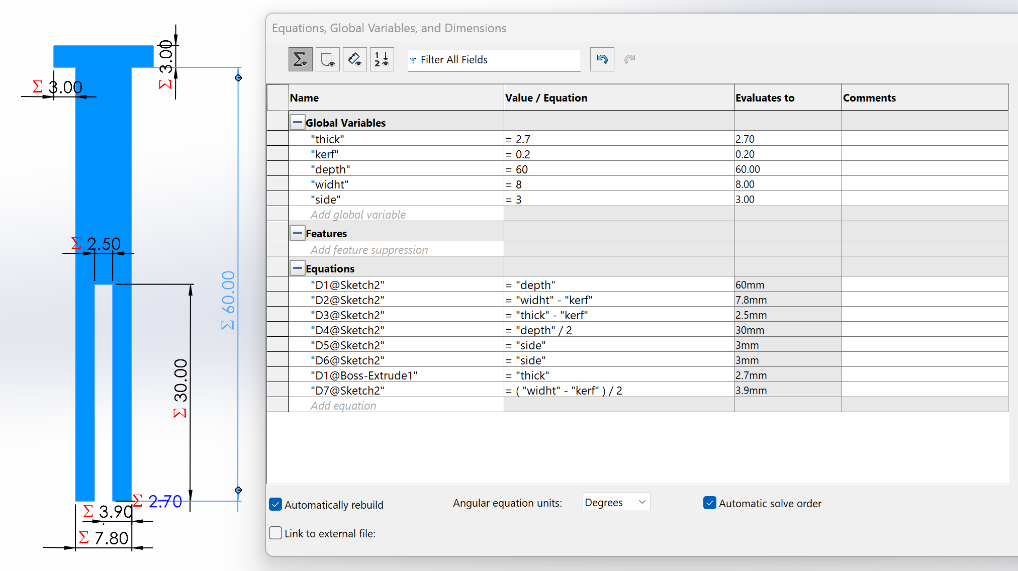
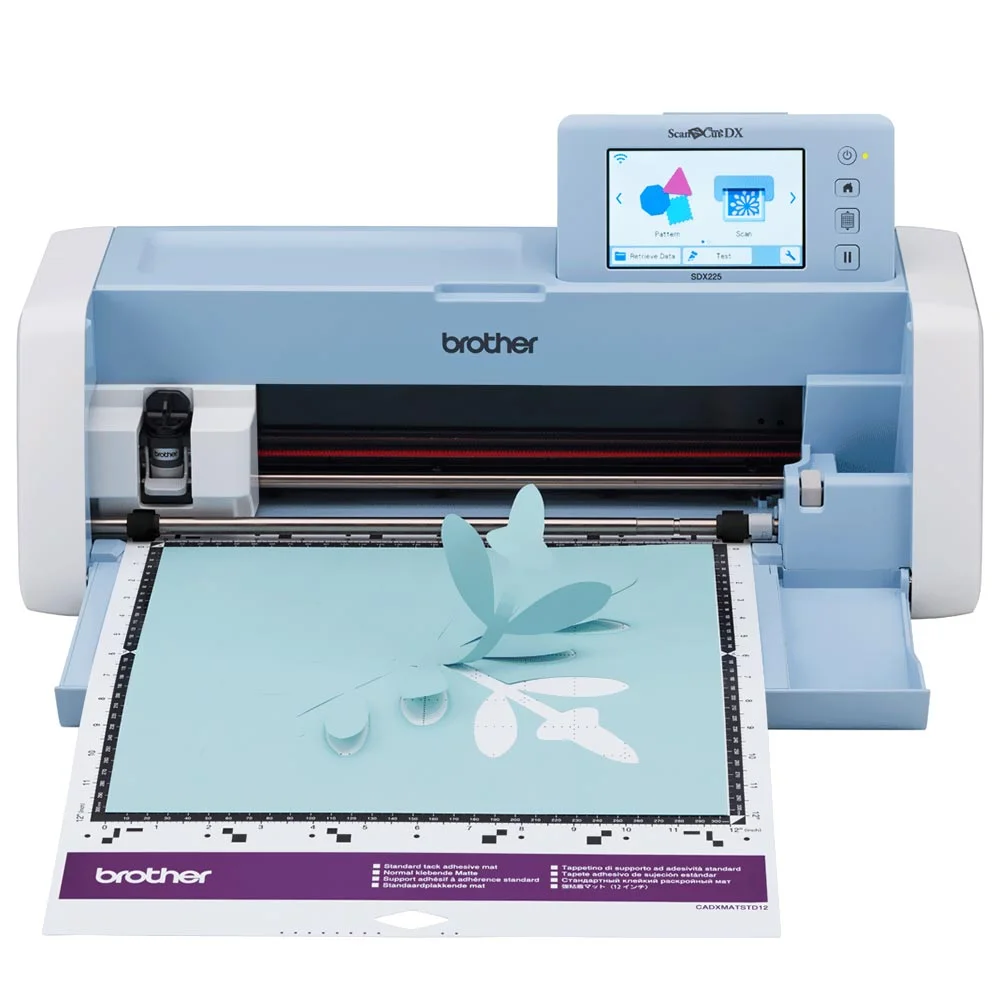
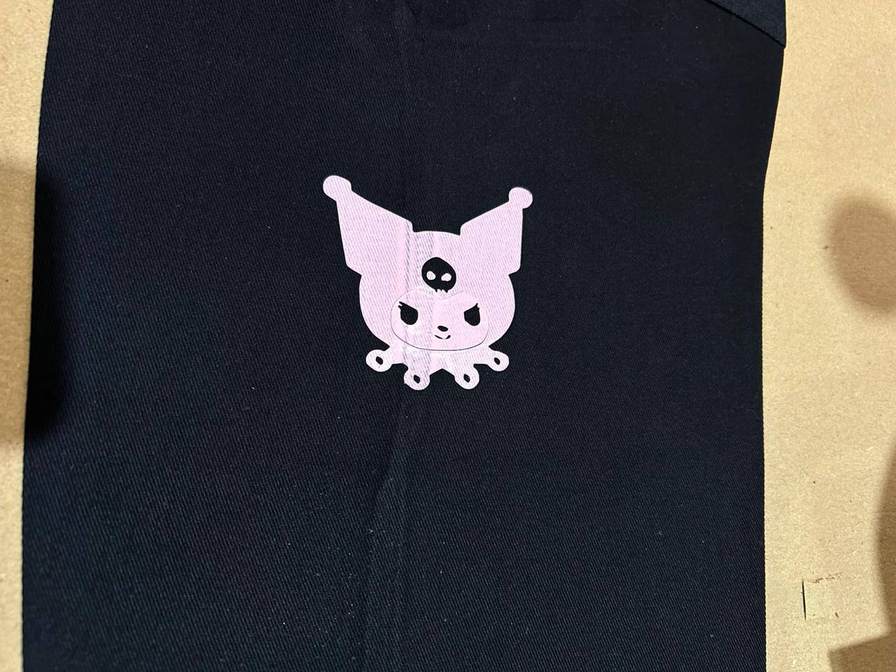 Fig 12. Final Vinyl Design