This week focused on comparing 2D and 3D design programs. In the 2D section, I created and edited the logo for my final project using different both of the softwares i choosed. For 3D, I designed the first prototype of the wearable accessory I plan to build.
List of Softwares
2D
2D design works on flat surfaces. It is divided into Raster (pixels for sketching and images) and Vector (mathematical lines).
Photoshop
Inkscape
Illustrator
Adobe Fresco
Procreate
AutoCAD
3D
3D software adds a third dimension (Z axis) to create volumetric objects.
SolidWorks
Catia
Tinkercad
Blender
Onshape
Fusion 360
For the 2D design assignment, I selected Inkscape and Adobe Fresco. To make a fair comparison between both software tools, I worked on the same task: editing the logo for my final project. Since I am not very experienced in digital drawing, I sketched the logo on paper first and asked Gemini to digitize it. Below are the original sketch and the prompt I used.
"A clean black and white vector illustration based exactly on the sketch in the photo"
Fig 2. Final logo
Softwares used
Inkscape Fundaments
Inkscape
Inkscape is a professional, free, and open-source vector graphics editor. Unlike raster software that uses pixels, Inkscape uses mathematical paths to create scalable images that do not lose quality when resized. It is widely used for logo design, technical illustrations, and typography
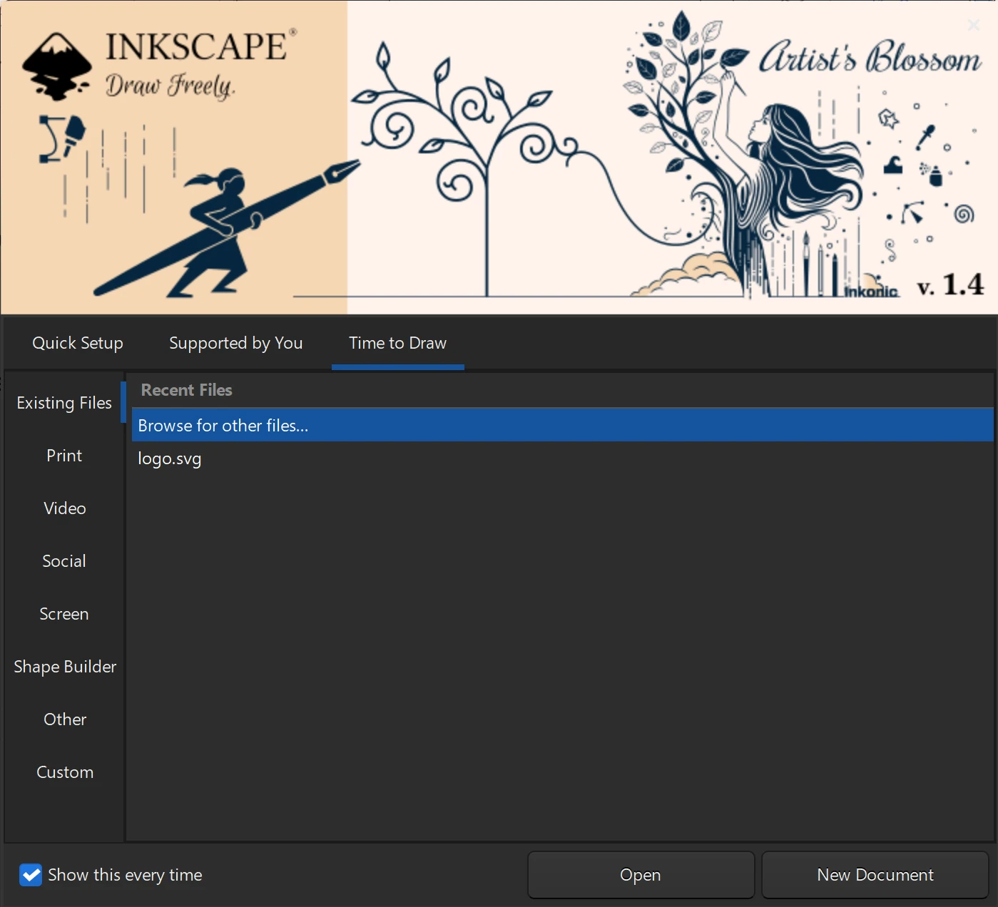
Welcome Screen
When you open Inkscape, the first thing you see is a welcome screen. Here, you have the option to open an existing file or create a new document.
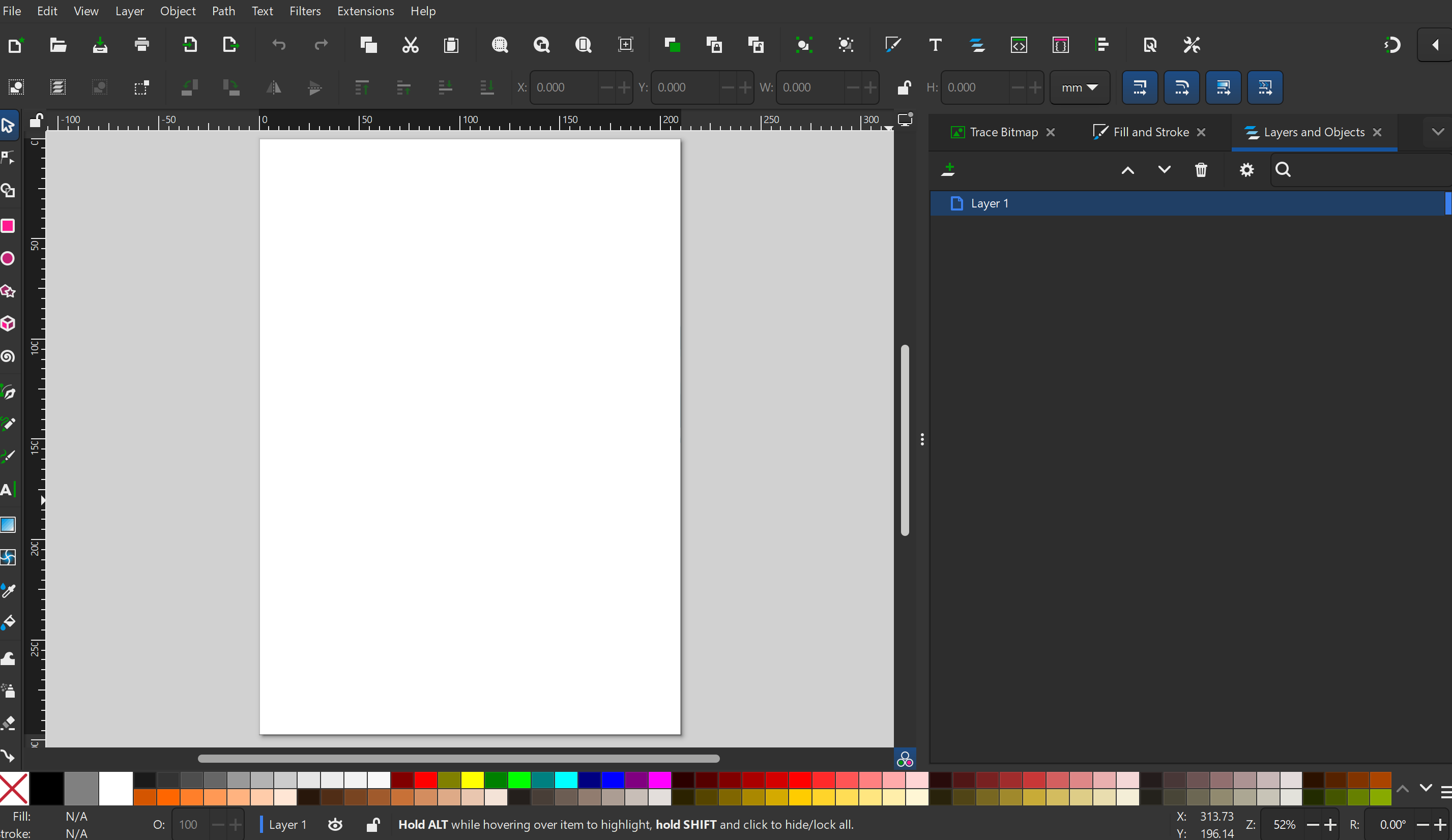
Main Workspace
Once you are in the main workspace, you will see the canvas in the center. The main tools and menus are located on the left and upper side, while the specific settings for the tool you are currently using will appear on the right panel.
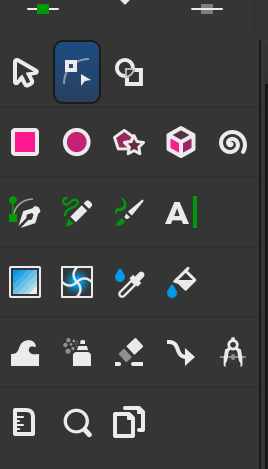
Tools
The Toolbox is located on the left side. Here, you can select the necessary tools to draw and edit your design.
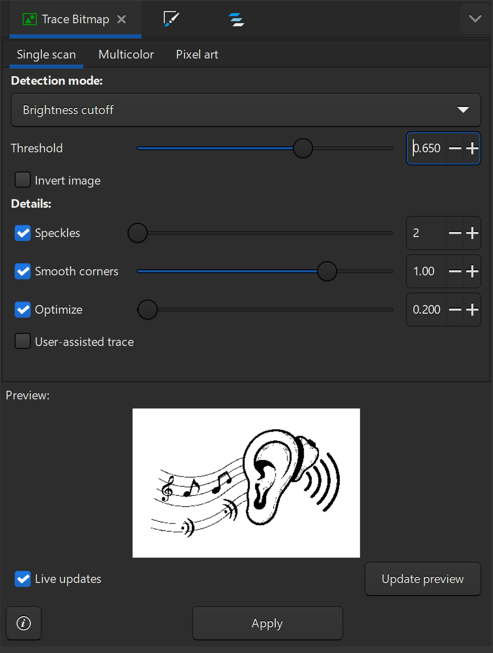
Trace Bitmap
Trace Bitmap is a feature in Inkscape that allows you to convert a raster image (like a JPG or PNG) into a vector image. This is useful for creating scalable graphics from existing images. Go to the Path menu and select Trace Bitmap.
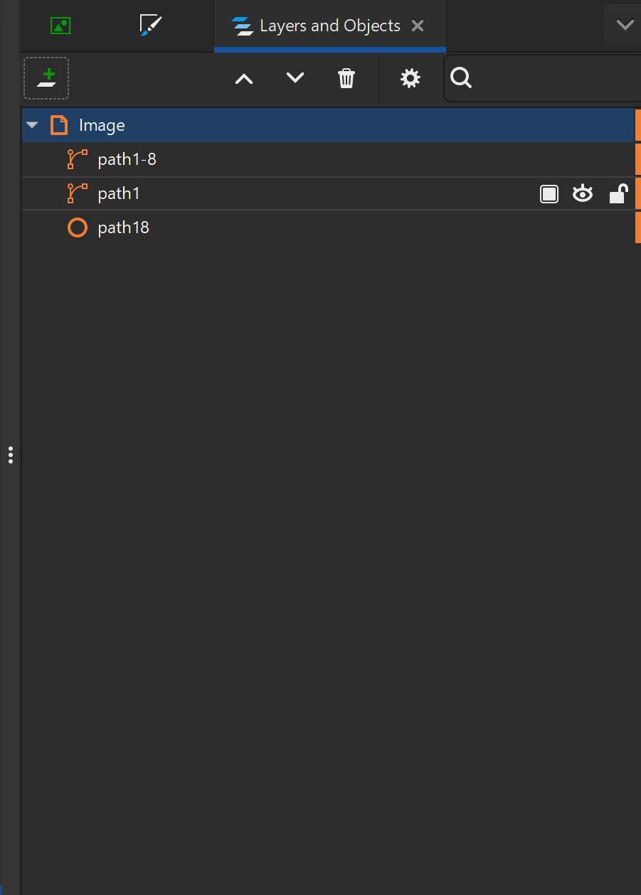
Layers and Objects
Layers are used to organize your design. You can add, delete, and reorder layers. Objects within each layer can be selected and edited independently.Go to the Layer menu and select Layers and Objects.
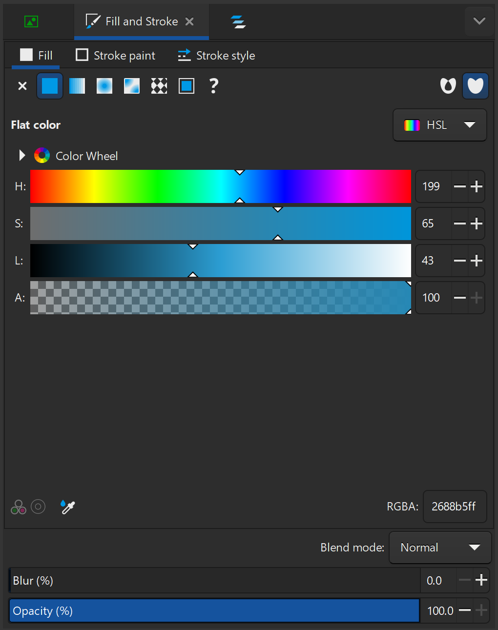
Fill and Stroke
Fill refers to the color or pattern inside an object, while Stroke refers to the outline of an object. You can customize both fill and stroke properties in the right panel. Go to the Object menu and select Fill and Stroke.
Using these tools, I designed and edited my logo. I used layers to organize the different shades and added a circle to give the design a more complete look.
Fig 3. My logo - Inkscape
Adobe Fundaments
Adobe Fresco
Adobe Fresco is a digital drawing and painting app built specifically for stylus and touch devices. It stands out for combining raster brushes (pixels), vector brushes (scalable lines), and Live Brushes that realistically simulate watercolor and oil painting behavior in a single workspace.
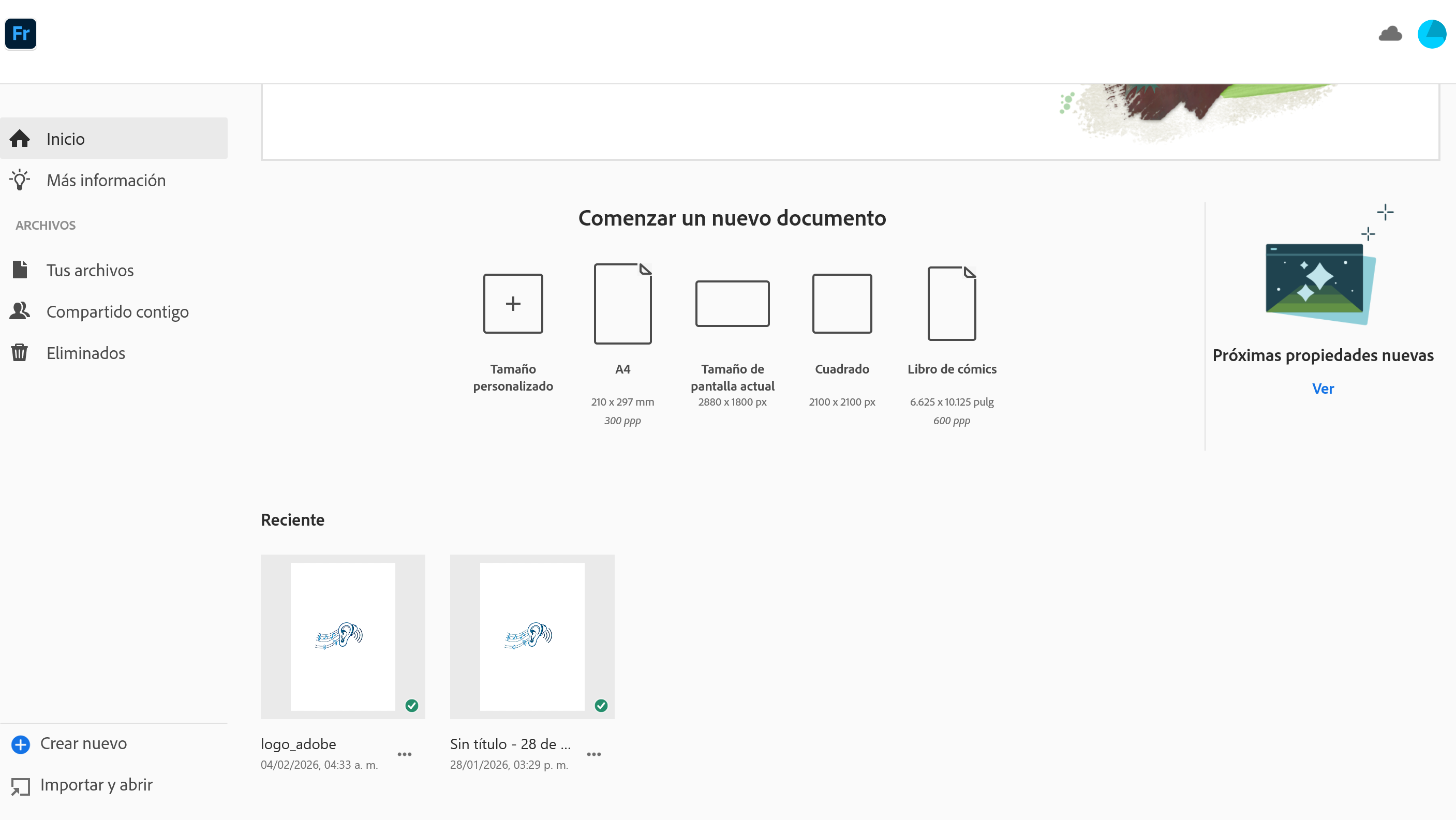
Home Page
The home screen allows you to either create a new canvas or import a file you have already saved.
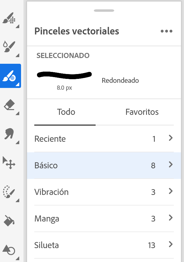
Tools Panel
The toolbar is located on the left side of the screen. This is where you select your brushes, eraser, and selection tools. The most unique feature of Fresco is that it offers three types of brushes: Pixel Brushes, Live Brushes, and Vector Brushes.
Vector Brushes
Vector brushes are scalable and maintain quality at any size. They are ideal for creating clean, crisp lines and shapes.
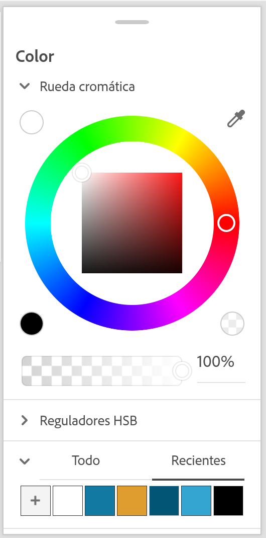
Color Panel
The color panel is located on the right side of the screen. It allows you to select and adjust colors for your drawing.
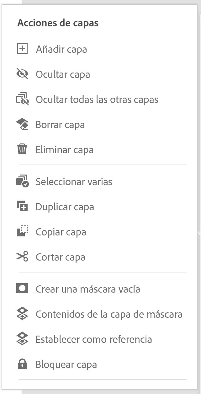
Layers Panel
The layers panel is located on the right side of the screen. It allows you to manage multiple layers in your drawing.
Applying these basic principles, I edited my logo. I used different color tones to give the design more depth.
Fig 4. My logo - Adobe Fresco
My opinion
I preferred using Inkscape to edit and design my logo. It was easier to customize the colors, and the final result feels more professional. The automatic vectorization feature was key, as I didn't need to trace the image line by line, resulting in a much cleaner finish.
For the 3D design section, I selected SolidWorks and Blender. To effectively compare both tools, I designed a prototype of the wearable headband I am developing for my final project.
Softwares used
SOLIDWORKS Fundaments
SOLIDWORKS
SOLIDWORKS is a parametric 3D CAD software widely used in mechanical engineering and product design. It allows users to create precise solid models, complex assemblies, and technical 2D drawings using a feature-based approach.
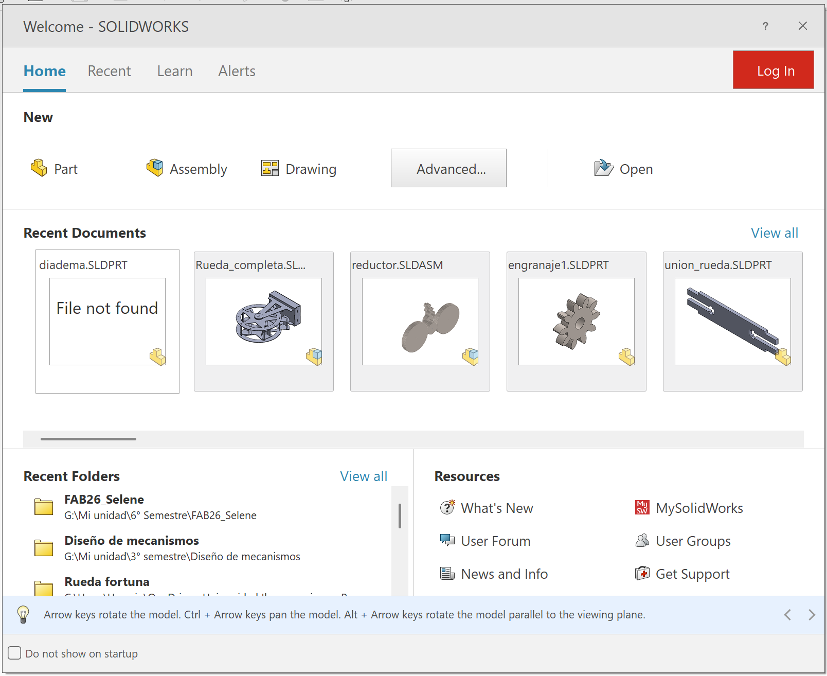
Home Page
Upon opening SolidWorks, the Welcome Screen appears. From here, you can create a new document (Part, Assembly, or Drawing) or open a recent file you have been working on.
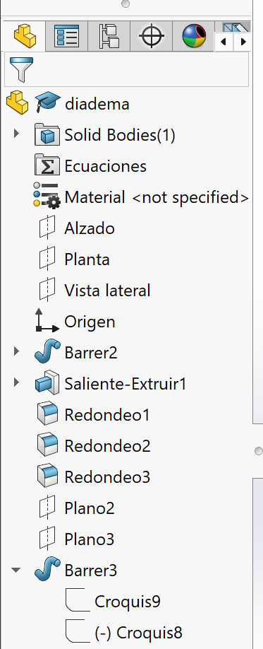
Feature Tree
The Feature Tree in SolidWorks displays all the features and operations that have been added to a part or assembly. It allows users to manage, edit, and reorder features in a hierarchical structure.
Tools
SolidWorks provides a wide range of tools for modeling, simulation, and documentation. These include sketching tools, feature tools, and assembly tools that help users build complex 3D models efficiently.
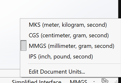
Units
You can modify the units in SolidWorks by clicking in the bottom right corner of the screen where the units are displayed. This opens a dialog box where you can select the desired unit system.
Using these tools , i was able to model a 3D version of my prototype in SolidWorks.
Fig 5. Prototype - SolidWorks
Blender Fundaments
Blender
Blender is a free and open-source 3D creation suite. It supports the entirety of the 3D pipeline—modeling, sculpting, animation, simulation, and rendering. It operates as a mesh-based modeler, making it excellent for creating organic shapes and complex artistic surfaces.
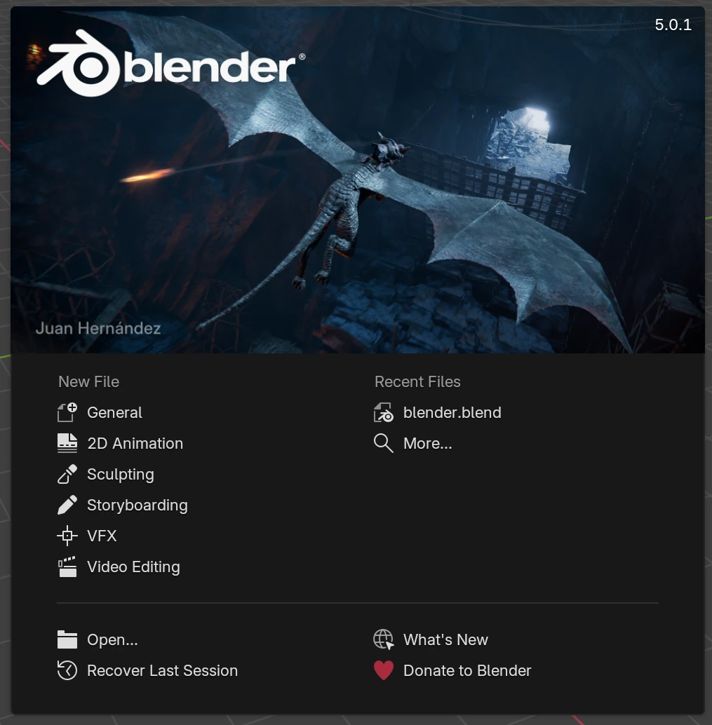
Welcome page
When you open Blender, the first thing you see is a welcome screen. Here, you have the option to open an existing file or create a new document.
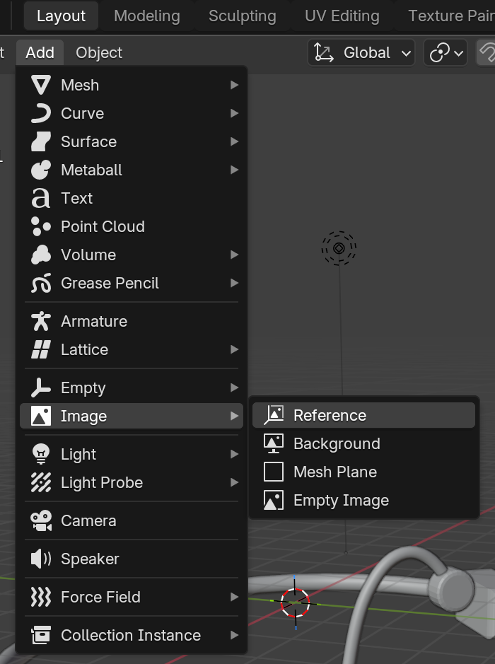
Reference
Blender allows you to import reference images to guide your modeling process. These can be added in the background of the 3D viewport.
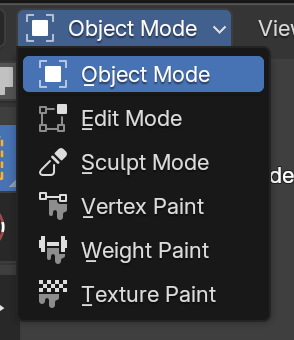
Modes
Blender has different modes for working with objects. The most common ones are Object Mode, Edit Mode, and Sculpt Mode.
Tools
Blender has a wide range of tools for modeling, sculpting, and rendering. These tools are organized in different panels and can be accessed through the menu on the right.
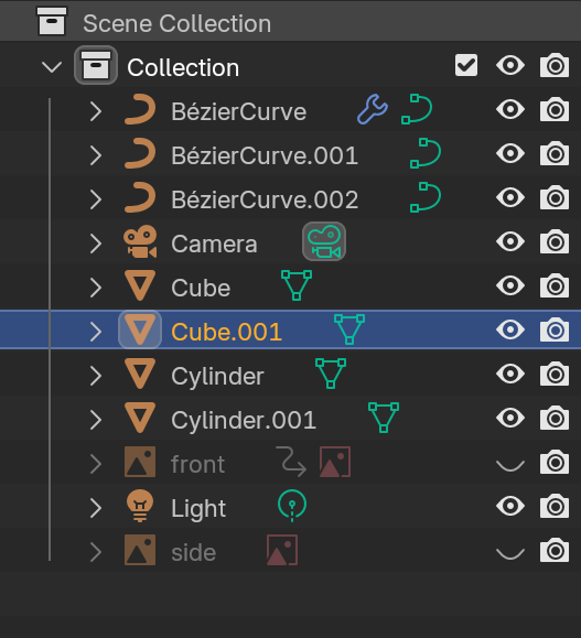
Scene Collection
Blender's scene panel allows you to manage and organize all the elements in your 3D workspace. It includes settings for lighting, camera, and rendering options.
Using these basic tools , i was able to model a 3D version of my prototype in Blender.
Fig 6. Prototype - Blender
My opinion
Although learning a new 3D software like Blender was a fun and interactive experience, I preferred using SolidWorks. I feel that the final finish is much cleaner and more precise. Additionally, achieving perfect symmetry and alignment was significantly easier thanks to its parametric tools.
SOLIDWORKS Render
To test the rendering tools in SolidWorks, I used a part that I had previously designed and saved.
Fig 7. Part
Rendering Process
Apply Appearances: Once your part is finished, go to the Appearances tab on the right task pane. Select your desired material (plastic, metal, glass, etc.) and drag it directly onto the model.
Fig 8. Appearance
Fig 9. Part with Appearance
Enable Visualize: Go to the SolidWorks Add-Ins tab at the top and enable SOLIDWORKS Visualize. After a moment, a new tab will appear in your CommandManager.
Fig 10. Add-Ins
Export: Open the new tab and select Export Simple. This will launch the standalone SolidWorks Visualize application with your model loaded.
Fig 11. SOLIDWORKS Visualize
Setup & Output: In the Visualize window, use the toolbar to adjust lighting, cameras, and the environment. To export the image, click the Output Tools icon (the silver camera) on the main toolbar.
Fig 12. Output Tools
Render Settings: In the pop-up menu, define the resolution, file format (JPG/PNG), and render quality (Passes). Finally, choose your destination folder and click Start Render.
Fig 13. Render Settings
Final Result
Here is the final rendered image
Fig 14. Final render
Compress videos
To compress the videos, I used FFmpeg, a free and open-source software suite capable of converting almost any audio and video format. This step is essential to keep the Git repository lightweight and ensure the website loads quickly for a better user experience.
How to install FFmpeg on Windows
Download: Get the latest 64-bit build (ZIP) from the builds page.
Extract: Unzip the folder and move it to a permanent location.
Environment Variables: Search for "Edit the system environment variables" in the Windows Start menu and open it.
Edit Path: Click the Environment Variables button. In the "System variables" section, find the variable named Path, select it, and click Edit.
Add Bin: Click New on the right side and paste the full path to the bin folder inside your FFmpeg directory.
I executed the following command in the terminal to compress the file.
 Fig 1. Sketch of the logo
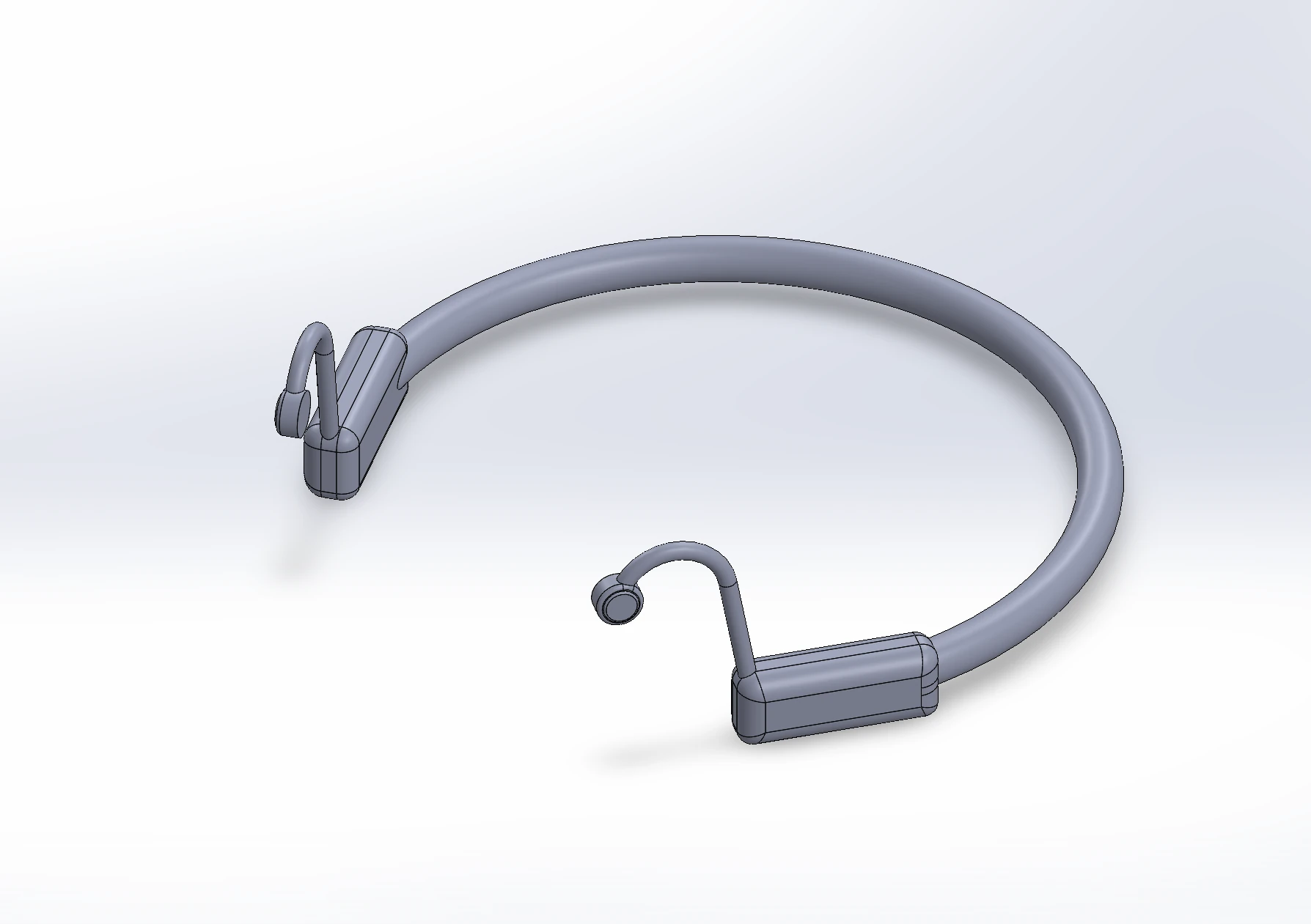 Fig 5. Prototype - SolidWorks
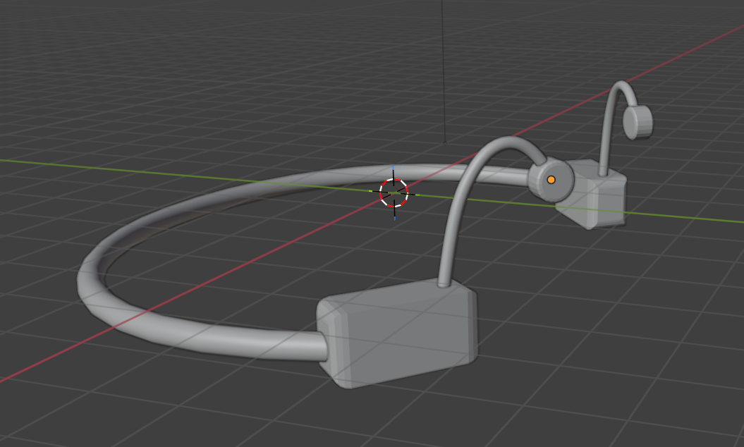 Fig 6. Prototype - Blender
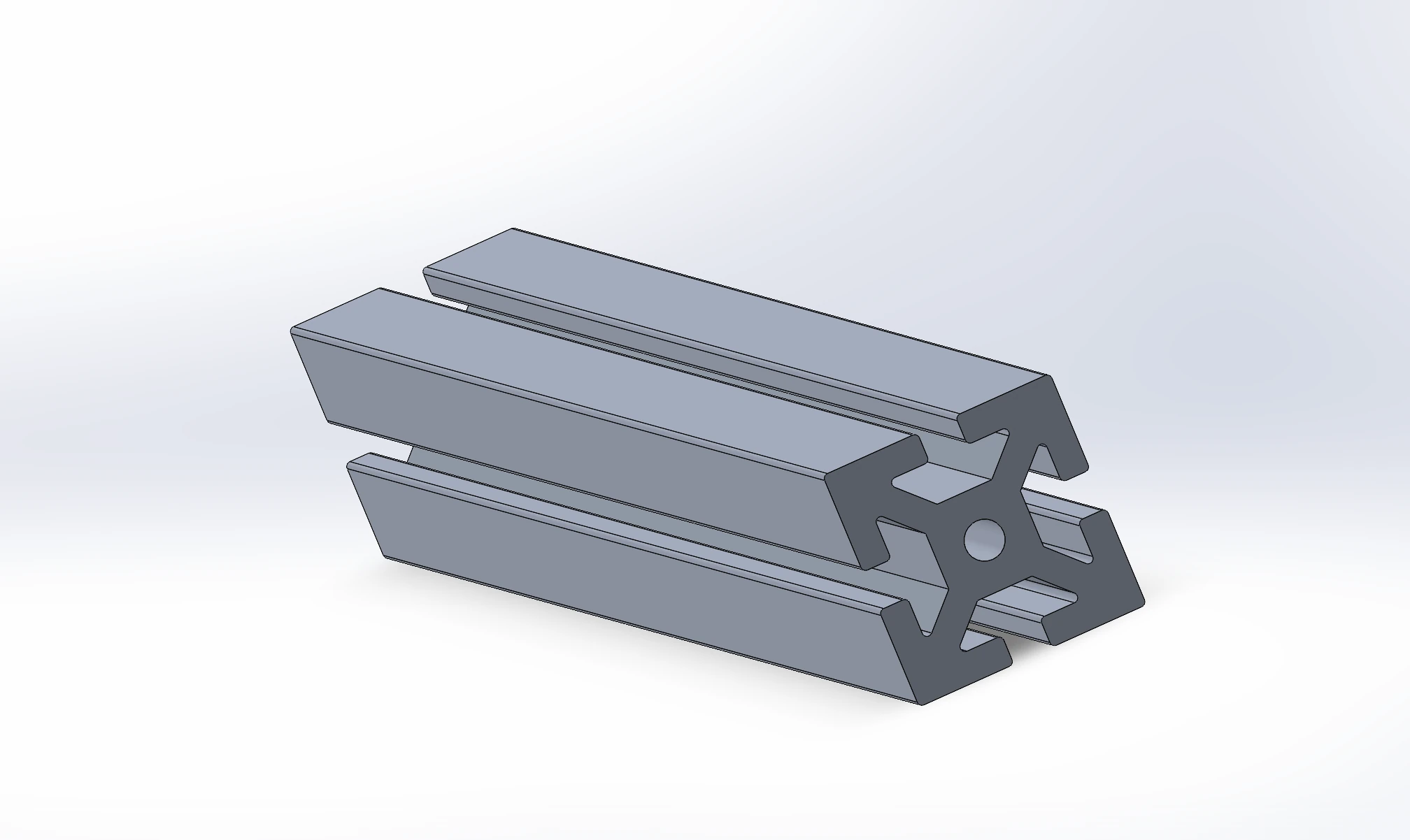 Fig 7. Part
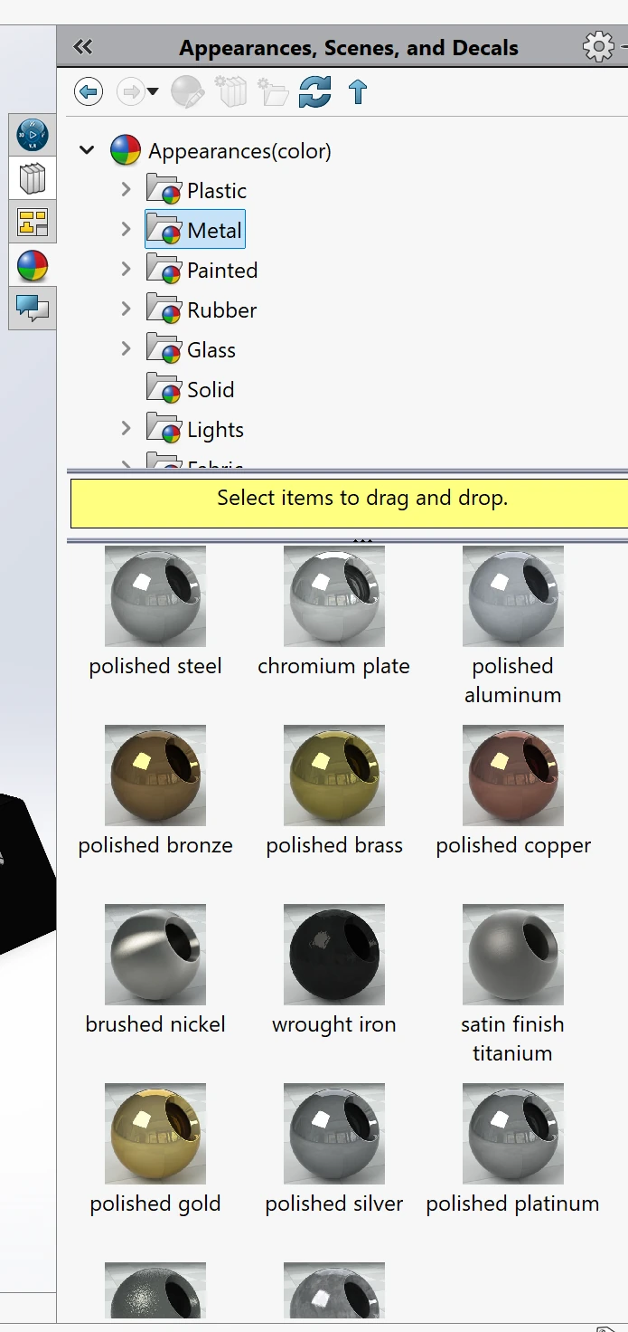 Fig 8. Appearance
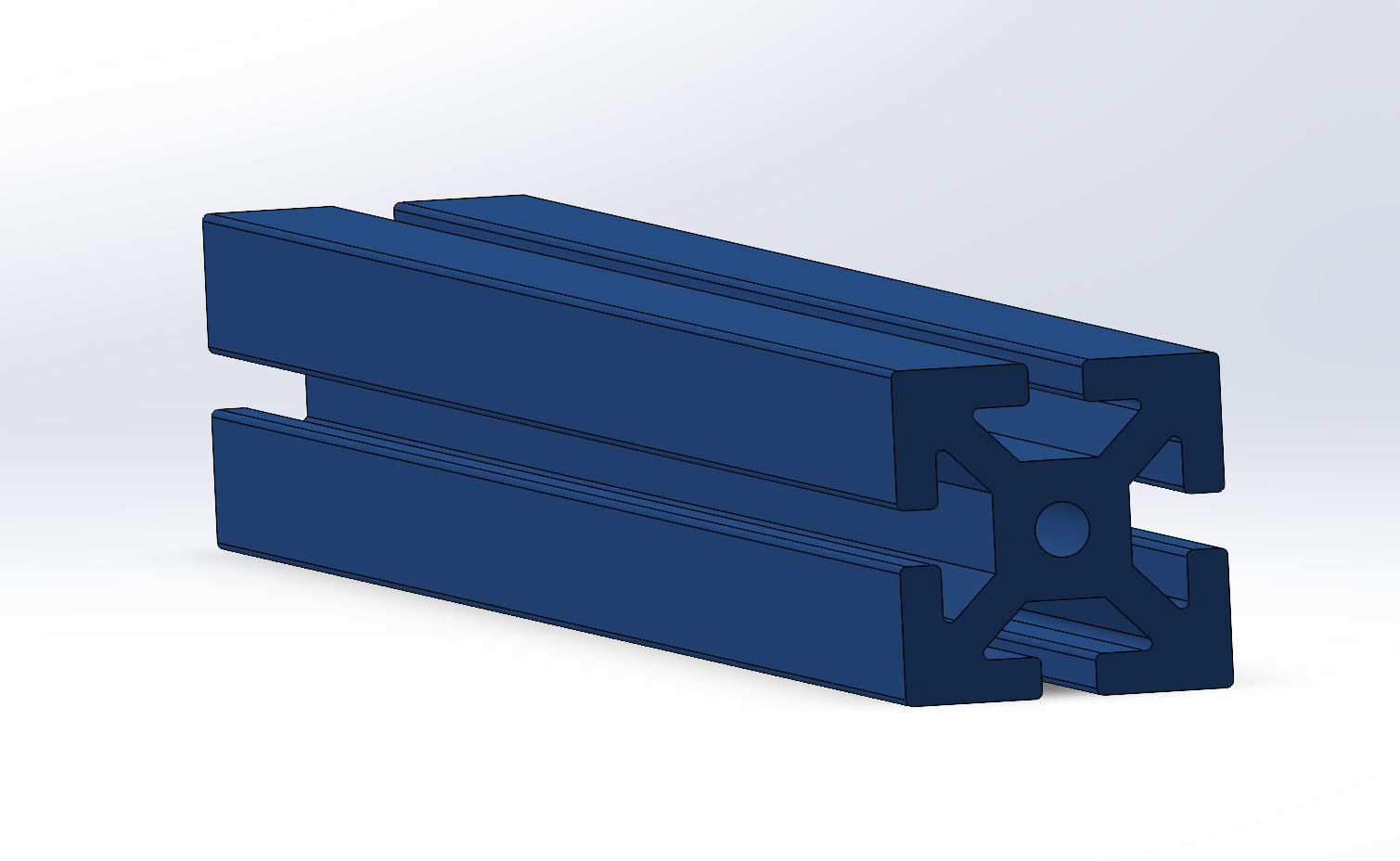 Fig 9. Part with Appearance
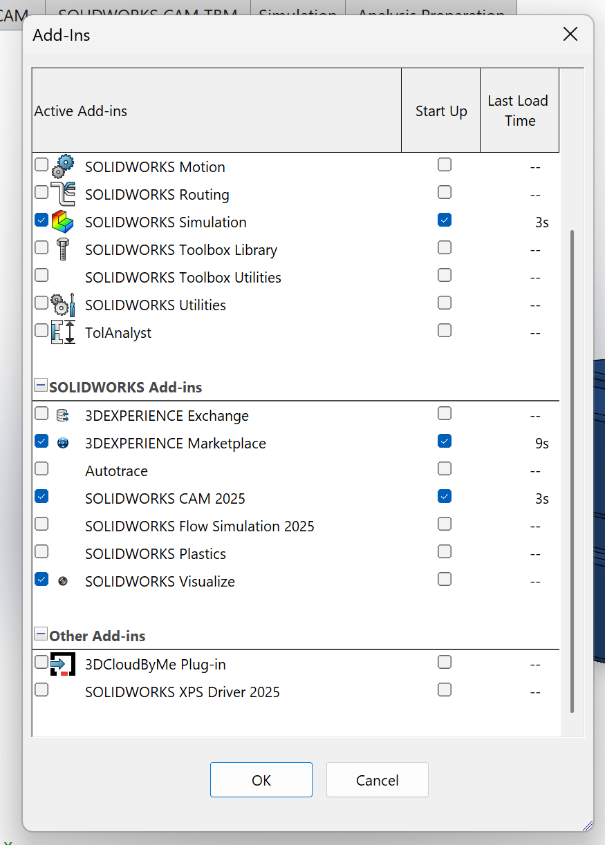 Fig 10. Add-Ins
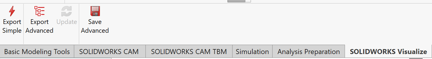 Fig 11. SOLIDWORKS Visualize
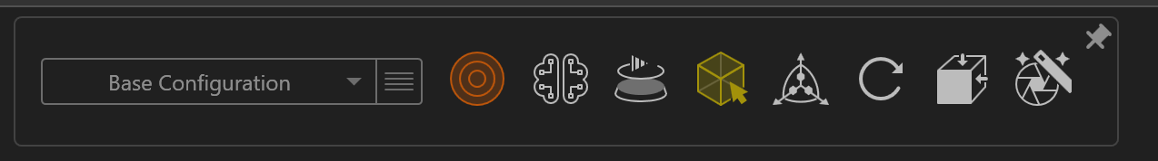 Fig 12. Output Tools
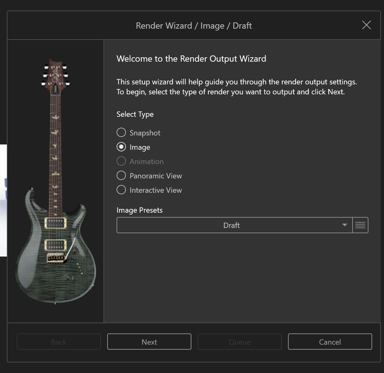 Fig 13. Render Settings
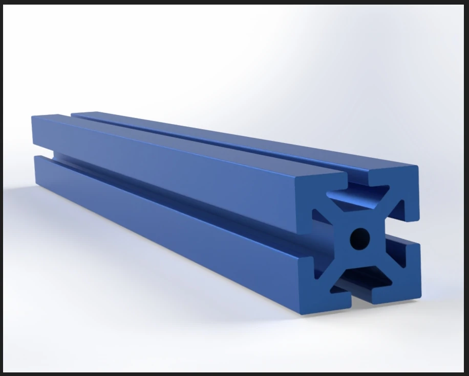 Fig 14. Final render
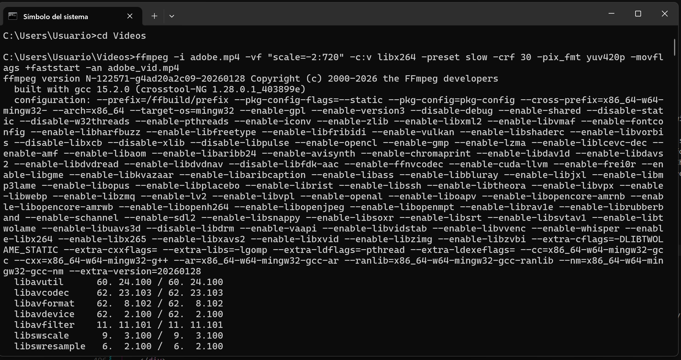 Fig 15. Comman in terminal
 Fig 4. Scale Image
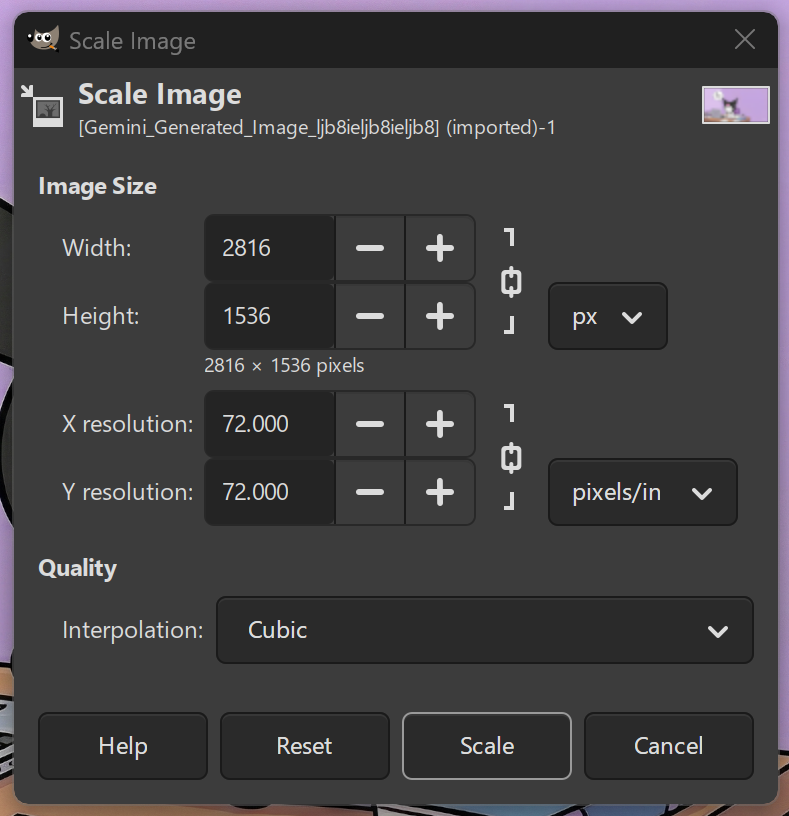 Fig 5. Image resolution