The objective of this week was to browse the datasheet for a microcontroller to understand its technical specifications and pinout. The assignment required writing and testing a program for a microcontroller to interact with local input and/or output devices and communicate through remote wired or wireless connections.
For this assignment, I worked with the Raspberry Pi Pico 2, taking advantage of its extensive GPIO flexibility. However, I am considering to use the XIAO ESP32-C3 for my final project. Its compact and practical form factor is perfect for my design's portability, and its integrated Wi-Fi and Bluetooth capabilities offer the specific connectivity features I intend to use for my final application.
To ensure the correct integration of the components and to understand the electrical limits of each board, I consulted the official technical documentation. Reviewing the Datasheets was essential to identify the pinout mapping, voltage tolerances, and the specific capabilities of the RP2350 and ESP32-C3 architectures.
Here are the datasheets I used:
| Feature | Raspberry Pi Pico 2 | XIAO ESP32-C3 |
|---|---|---|
| Microcontroller | RP2350 (Dual-core) | ESP32-C3 (Single-core) |
| Architecture | ARM Cortex-M33 / RISC-V | RISC-V |
| Clock Speed | 150 MHz | 160 MHz |
| SRAM Memory | 520 KB | 400 KB |
| Flash Memory | 4 MB | 4 MB |
| GPIO Pins | 26 multi-function pins | 11 digital pins |
| Analog Inputs | 4 channels (12-bit) | 4 channels (12-bit) |
| Communication | 2 × I2C, 2 × SPI, 2 × UART | 1 × I2C, 1 × SPI, 1 × UART |
| Wireless | None | Wi-Fi 2.4GHz & Bluetooth 5.0 |
| Languages | C/C++, MicroPython, CircuitPython | C/C++ (Arduino), MicroPython, ESP-IDF |
| Operating Voltage | 3.3V | 3.3V |
| Dimensions | 21 mm x 51 mm | 17.5 mm x 21 mm |
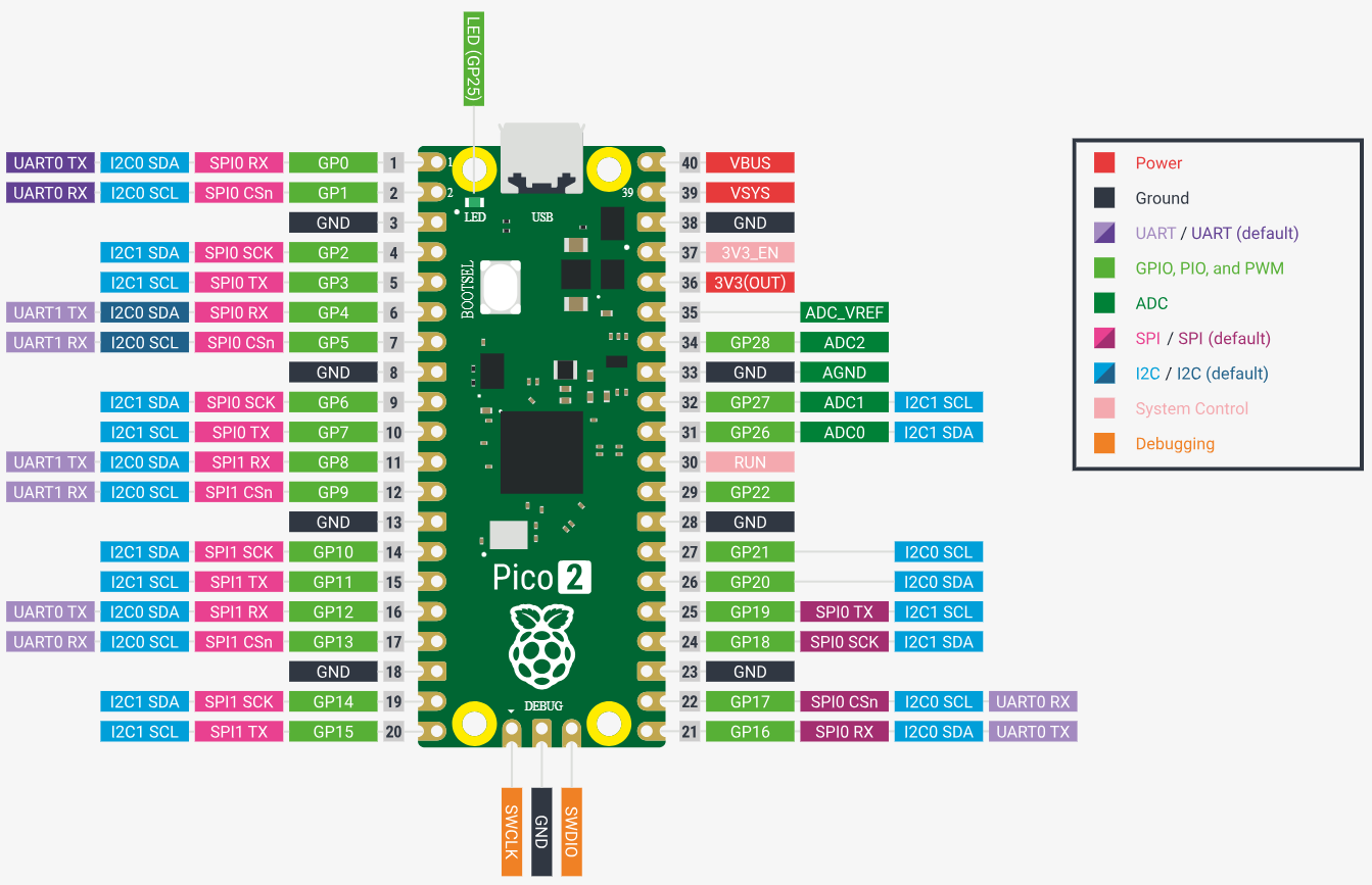 Fig 1. Raspberry Pi Pico 2 Pinout
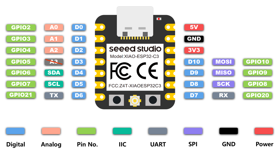 Fig 2. XIAO ESP32-C3 Pinout
GPIO (General Purpose Input/Output) are the physical pins on the microcontroller that can be programmed to either be an Input (reading data) or an Output (sending signals) to interact with external components.
The microcontroller supports multiple programming languages, including C/C++, MicroPython, and CircuitPython. These languages allow developers to write code that can be compiled or interpreted to control the microcontroller's behavior.
To program the Raspberry Pi Pico 2 , I used MicroPython. Below is a quick reference guide to the syntax and logic of MicroPython:
Comments are essential for documenting the workflow, and the print() function is used to display data in the Serial Monitor for debugging.
Variables are used to store information that the program can process later:
True or False.Basic operators used for calculations:
Conditionals allow the microcontroller to make decisions based on sensor inputs or states:
And (all conditions must be true) and Or (at least one condition must be true).Loops are used to repeat tasks, such as reading a sensor continuously:
while True: for the main program loop).To maintain clean and modular code, we use functions and external modules:
import time or import machine grants access to hardware-specific tools.Embedded systems can encounter unexpected hardware errors (e.g., a disconnected sensor). Error handling prevents the entire program from crashing:
To program the XIAO ESP32-C3, I used Arduino. Arduino is based on C++, which is a compiled language that requires specific structures and data types. Below is a reference guide to the fundamental concepts:
Every Arduino program (sketch) must have two main functions:
void setup() { }: Runs once when the board starts. Used for initialization (pin modes, serial start).void loop() { }: Runs repeatedly. This is where the main logic of the controller happens.Unlike Python, C++ is very strict about punctuation:
//: Single-line comments./* */: Multi-line comments.In Arduino, you must declare the type of data a variable will hold:
int: Integers (e.g., int ledPin = 10;).float: Decimal numbers (e.g., 3.14).bool: Boolean (true or false).char: Single characters.String: Text sequences.Decisions are made using if-statements with parentheses:
== (equal to), != (not equal), > (greater), < (less).&& (AND), || (OR), ! (NOT).Used to repeat actions within the code:
for (int i=0; i < 5; i++) { }: Repeats code a fixed number of times.while (condition) { }: Repeats code as long as a condition is true.Arduino provides specific commands to interact with the GPIOs:
pinMode(pin, mode): Configures a pin as INPUT or OUTPUT.digitalWrite(pin, value): Sends a HIGH (3.3V) or LOW (0V) signal.analogRead(pin): Reads voltage from an analog pin (0-4095 on ESP32-C3).Serial.print(): Sends data to the computer for debugging.External code can be included to add functionality:
#include <Wire.h>: Used for I2C communication.#include <WiFi.h>: Used for the wireless capabilities of the ESP32-C3.To test the code without needing the physical hardware, I used the online simulator Wokwi. This platform allows you to create virtual circuits and write code to see how it would behave in real life. It was a great tool for debugging and understanding the logic of my programs before uploading them to the actual microcontroller. I used it to simulate the same circuit on both the Raspberry Pi Pico 2 and the XIAO ESP32-C3, in the languages MicroPython and Arduino.
For my final project, I plan to use two vibration motors and two electret microphones. Since these specific components are not available in the simulator, I substituted the microphones with linear potentiometers to simulate variable sound levels, and the vibration motors with buzzers to test the response logic. I also added two LEDs for better visual feedback. The system is designed so that when one "microphone" receives a stronger signal, the corresponding "vibration motor" on that side activates, allowing me to verify my directional detection logic.
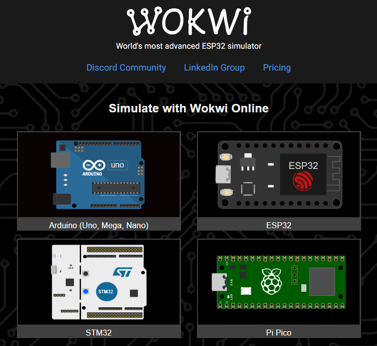 Fig 3. Selecting the microcontroller
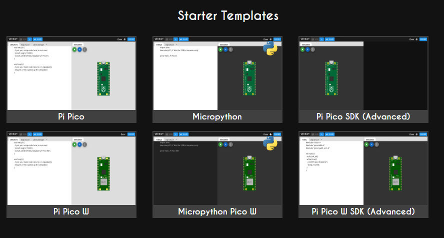 Fig 4. Selecting the programming language
 Fig 5. Selecting a template
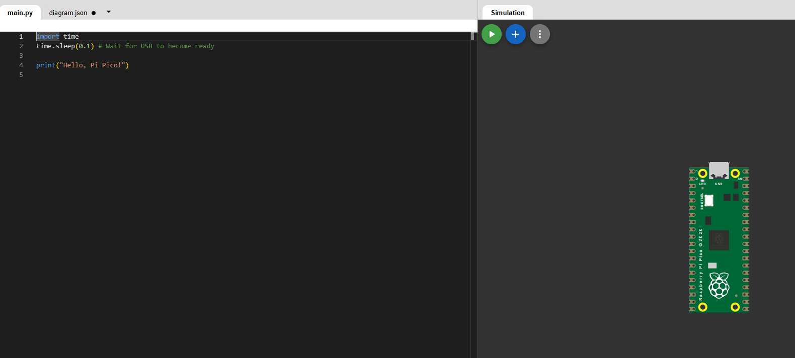 Fig 6. Main editor window
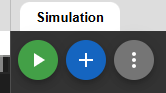 Fig 7. Simulation menu buttons
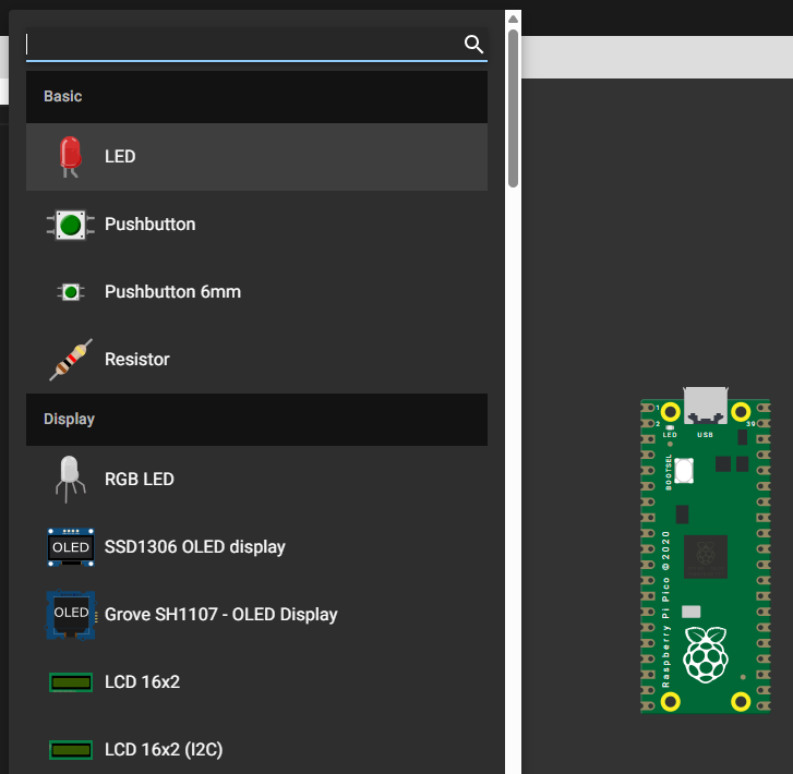 Fig 8. Components gallery
 Fig 9. Wiring components
Here are the simulations I created for both microcontrollers. The first one is the simulation for the Raspberry Pi Pico 2 programmed in MicroPython, and the second one is the simulation for the XIAO ESP32-C3 programmed in Arduino.
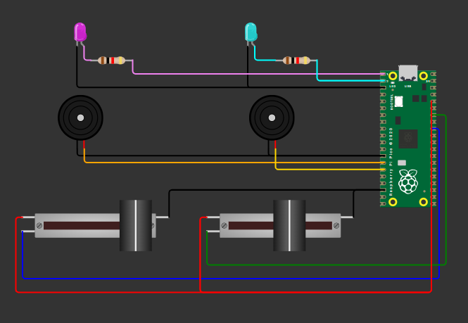 Fig 10. Raspberry Pi Pico 2 circuit
                # Import hardware control libraries
                from machine import Pin, ADC, PWM
                import time

                # Initialize ADC for the potentiometers on GPIO 27 and 28
                pot1 = ADC(Pin(27))
                pot2 = ADC(Pin(28))

                # Initialize Digital Output pins for the LEDs on GPIO 0 and 1
                led1 = Pin(0, Pin.OUT)
                led2 = Pin(1, Pin.OUT)

                # Initialize PWM for buzzers on GPIO 10 and 11 to control sound
                buzzer1 = PWM(Pin(10))
                buzzer2 = PWM(Pin(11))

                # Function to turn off all outputs (LEDs and sound)
                def silence():
                    led1.value(0)          # Turn off LED 1
                    led2.value(0)          # Turn off LED 2
                    buzzer1.duty_u16(0)    # Set buzzer 1 volume to 0
                    buzzer2.duty_u16(0)    # Set buzzer 2 volume to 0

                # Main execution loop
                while True:
                    # Read analog values from potentiometers (range 0-65535)
                    val1 = pot1.read_u16()
                    val2 = pot2.read_u16()

                    # Print values to the Serial Monitor
                    print(f"Pot1: {val1} | Pot2: {val2}")

                    # Condition 1: If both potentiometers are below a certain threshold, stay silent
                    if val1 < 20000 and val2 < 20000:
                        silence()

                    # Condition 2: If Pot 1 is significantly higher than Pot 2
                    elif val1 > (val2 + 1000):
                        led1.value(1)           # Turn on LED 1
                        led2.value(0)           # Turn off LED 2
                        buzzer1.freq(1000)      # Set buzzer 1 frequency to 1000Hz
                        buzzer1.duty_u16(32768) # Play sound
                        buzzer2.duty_u16(0)     # Mute buzzer 2

                    # Condition 3: If Pot 2 is significantly higher than Pot 1
                    elif val2 > (val1 + 1000):
                        led1.value(0)           # Turn off LED 1
                        led2.value(1)           # Turn on LED 2
                        buzzer2.freq(1500)      # Set buzzer 2 frequency to 1500Hz
                        buzzer2.duty_u16(32768) # Play sound
                        buzzer1.duty_u16(0)     # Mute buzzer 1

                    # If values are too close, turn everything off
                    else:
                        silence()

                    time.sleep(0.1)
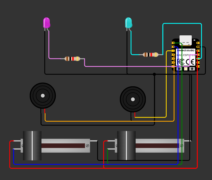 Fig 11. XIAO ESP32-C3 circuit
            #include

            const int pot1Pin = 3;  // Analog input from Potentiometer 1
            const int pot2Pin = 2;  // Analog input from Potentiometer 2
            const int led1 = 10;    // Digital output for LED 1
            const int led2 = 9;     // Digital output for LED 2
            const int buzzer1 = 5;  // PWM output for Buzzer 1
            const int buzzer2 = 4;  // PWM output for Buzzer 2

            // Thresholds adjusted for 12-bit resolution
            const int threshold = 500; // Minimum value to trigger activation
            const int margin = 200;    // Difference required to detect a clear "dominant" side

            // Function to reset all outputs to an idle state
            void silence() {
            digitalWrite(led1, LOW);
            digitalWrite(led2, LOW);
            noTone(buzzer1);
            noTone(buzzer2);
            }

            void setup() {
            Serial.begin(115200); // Initialize serial communication at 115200 baud

            // Configure pin modes
            pinMode(led1, OUTPUT);
            pinMode(led2, OUTPUT);
            pinMode(buzzer1, OUTPUT);
            pinMode(buzzer2, OUTPUT);

            analogReadResolution(12);

            }

            void loop() {
            // Read raw analog values from the sensors
            int val1 = analogRead(pot1Pin);
            int val2 = analogRead(pot2Pin);

            // Print values to the Serial Monitor for real-time debugging
            Serial.print("Pot1: "); Serial.print(val1);
            Serial.print(" | Pot2: "); Serial.println(val2);

            // Case 1: If both inputs are below the threshold, keep outputs OFF
            if (val1 < threshold && val2 < threshold) {
                silence();
            }
            // Case 2: If Pot 1 is higher than Pot 2 by at least the margin
            else if (val1 > (val2 + margin)) {
                digitalWrite(led1, HIGH);
                digitalWrite(led2, LOW);
                tone(buzzer1, 1000);
                noTone(buzzer2);     // Ensure the other buzzer is silent
            }
            // Case 3: If Pot 2 is higher than Pot 1 by at least the margin
            else if (val2 > (val1 + margin)) {
                digitalWrite(led1, LOW);
                digitalWrite(led2, HIGH);
                tone(buzzer2, 1500);
                noTone(buzzer1);     // Ensure the other buzzer is silent
            }
            // If values are too balanced, enter silence mode
            else {
                silence();
            }

            delay(50);
            }
To test the code on the physical microcontroller, I built the same circuit using the components I have available. To program the Raspberry Pi Pico 2, I used Visual Studio Code.
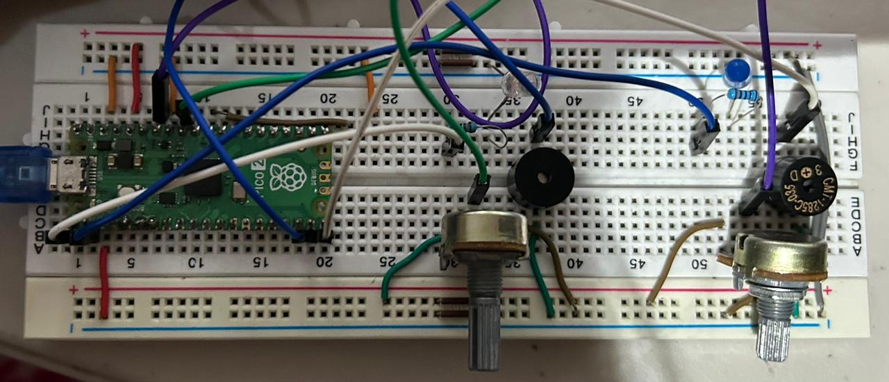 Fig 12. Physical circuit