This week we explored 3D scanning and printing techniques. The assignments included design and 3D print an object that could not be made subtractively (like CNC milling where material is removed) , and 3D scan an object and optionally print it. We could used different 3D printing technologies such as SLA, DLP and FDM , and experimented with various materials. The 3D scanning process involved using a structured light scanner to capture the geometry of an object, which was then processed and prepared for printing.
Group Assignment
Check here the group assignment of this week for more information about design rules test and characteristics about our printers.
3D Printing
What is 3D Printing?
3D printing, or Additive Manufacturing, is a process of creating three-dimensional solid objects from a digital file. Unlike subtractive manufacturing (like CNC milling), which cuts away material, 3D printing builds the object layer by layer from the bottom up.
To start, you need three things:
3D Model: A digital design created in CAD software (like Blender, SOLIDWORKS or Fusion 360)
Slicer Software: A program that converts the 3D model into G-code instructions for the printer
3D Printer and Material: The machine that physically builds the object layer by layer and the specific material used for printing (like PLA, ABS, or resin)
Common 3D Printing Technologies
FDM (Fused Deposition Modeling): This is the most common and accessible technology. It works by melting a plastic filament (PLA, ABS or PETG) and extruding it through a heated nozzle, which moves to "draw" each layer.
SLA (Stereolithography): SLA is a resin-based technology. It uses a UV laser to selectively cure (harden) liquid photopolymer resin in a vat, layer by layer. It produces high-resolution, smooth surfaces and is ideal for detailed and precise parts.
DLP (Digital Light Processing): DLP is very similar to SLA but uses a digital light projector screen instead of a laser. It flashes an image of the entire layer at once, making it significantly faster than SLA for certain objects.
SLS (Selective Laser Sintering): This is an industrial technology that uses a high-power laser to fuse small particles of plastic powder (usually Nylon) into a solid structure.
3D Model
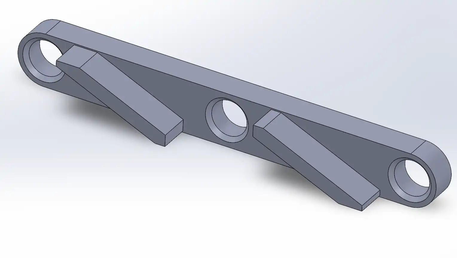
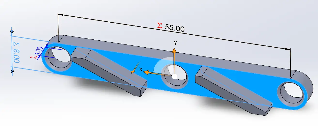
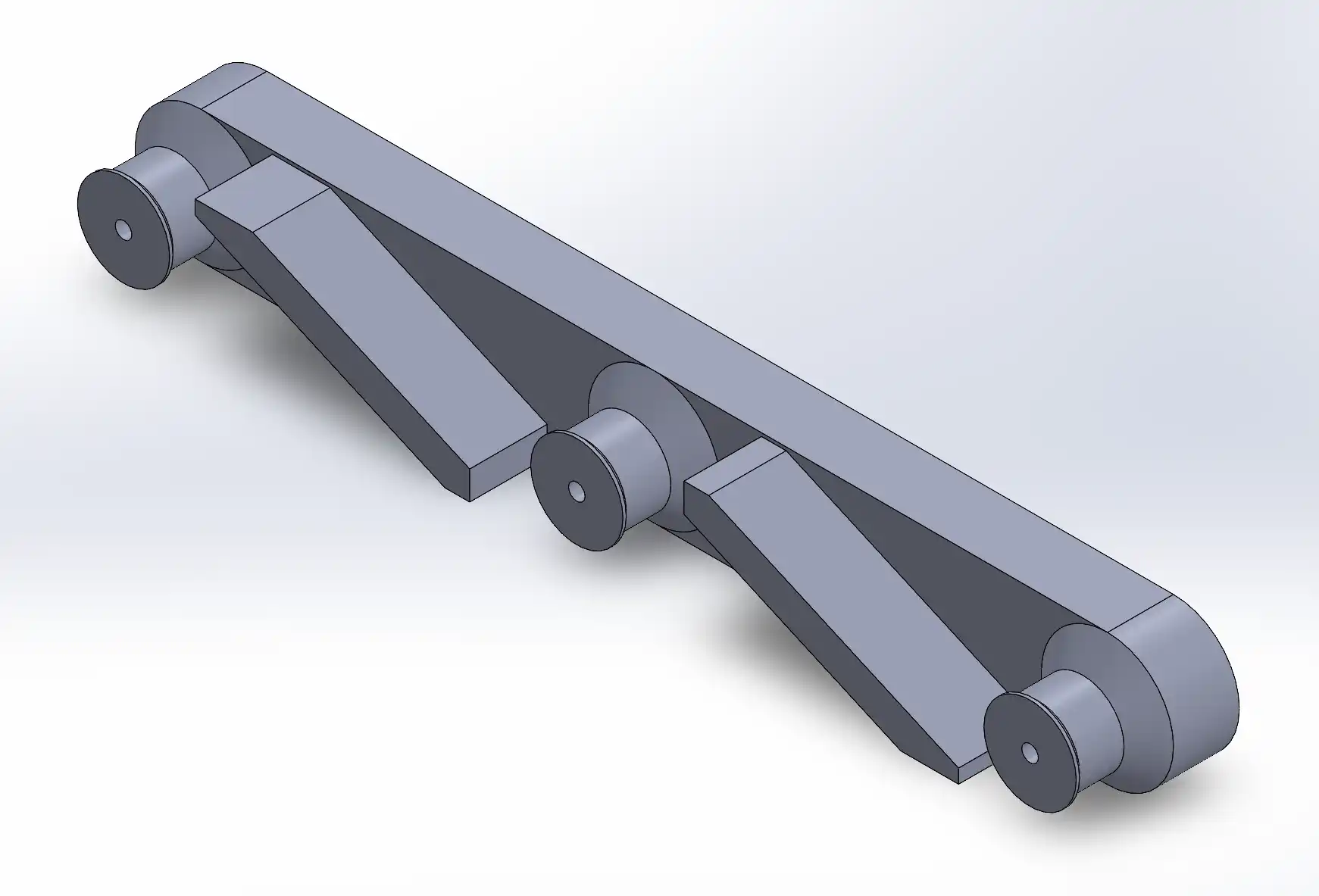
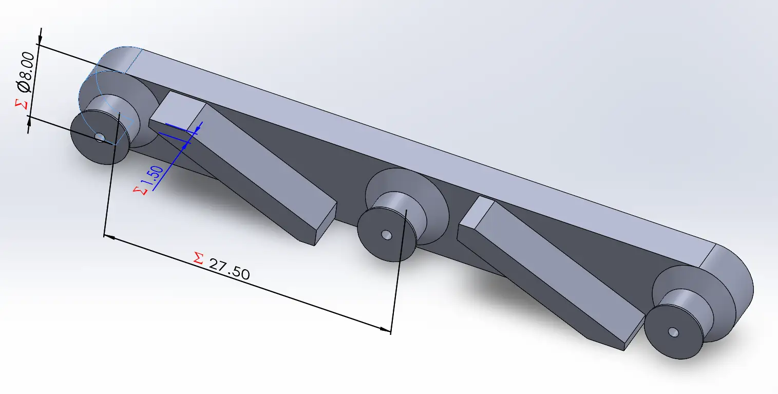
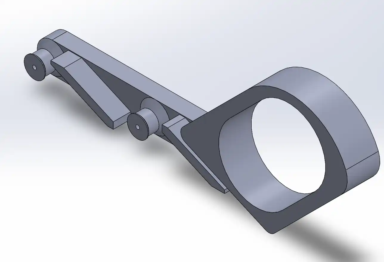
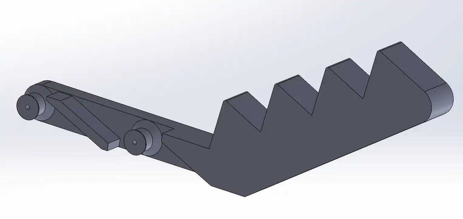
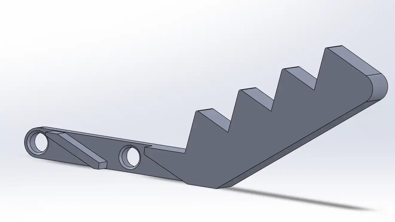
For this assignment, I designed a pair of extending tongs inspired by a mechanism found on MakerWorld. This object is a prime example of a design that cannot be manufactured subtractively (such as with CNC milling) for the following reasons:
Interlocking Joints: The mechanism consists of multiple interconnected pivot points and linkages. In a subtractive process, a CNC tool head would be unable to reach the tight internal gaps between these moving parts to remove material without damaging the surrounding structure.
Print-in-Place Geometry: The design relies on specific clearances between the joints to allow for mobility. 3D printing allows these pieces to be fabricated simultaneously in their final assembled positions. A milling machine, however, is limited by the "line of sight" of the cutting bit, making it impossible to carve out the internal spaces required for the tongs to extend and retract.
By using an additive approach, I was able to create a functional, moving mechanism in a single print that would otherwise require complex assembly or be impossible to carve from a solid block.
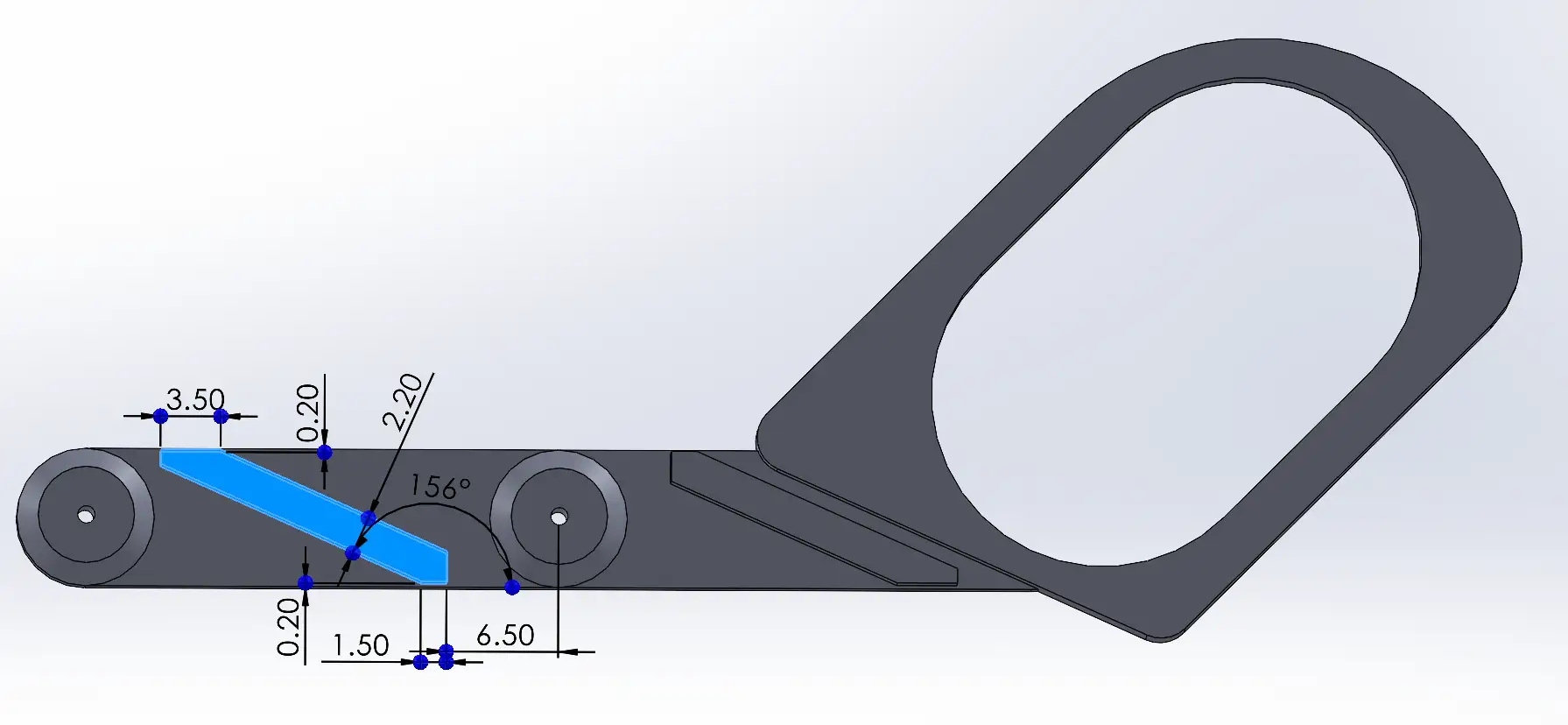
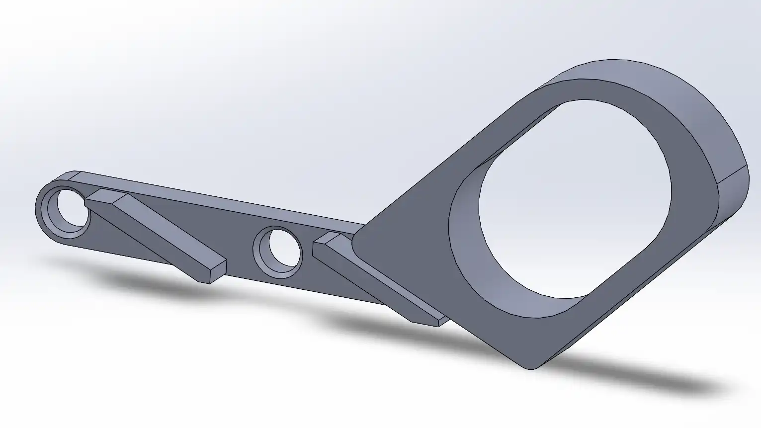
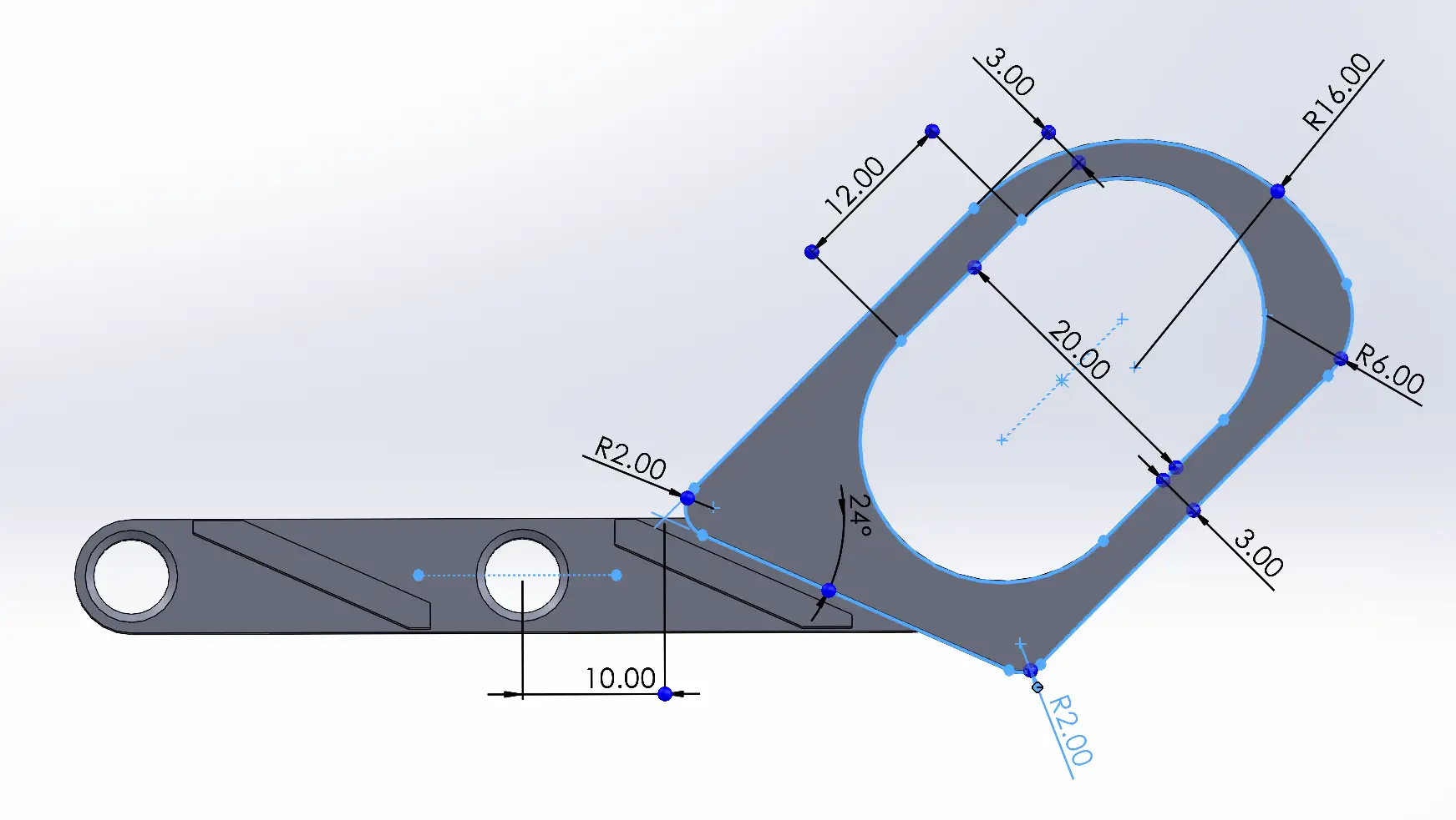
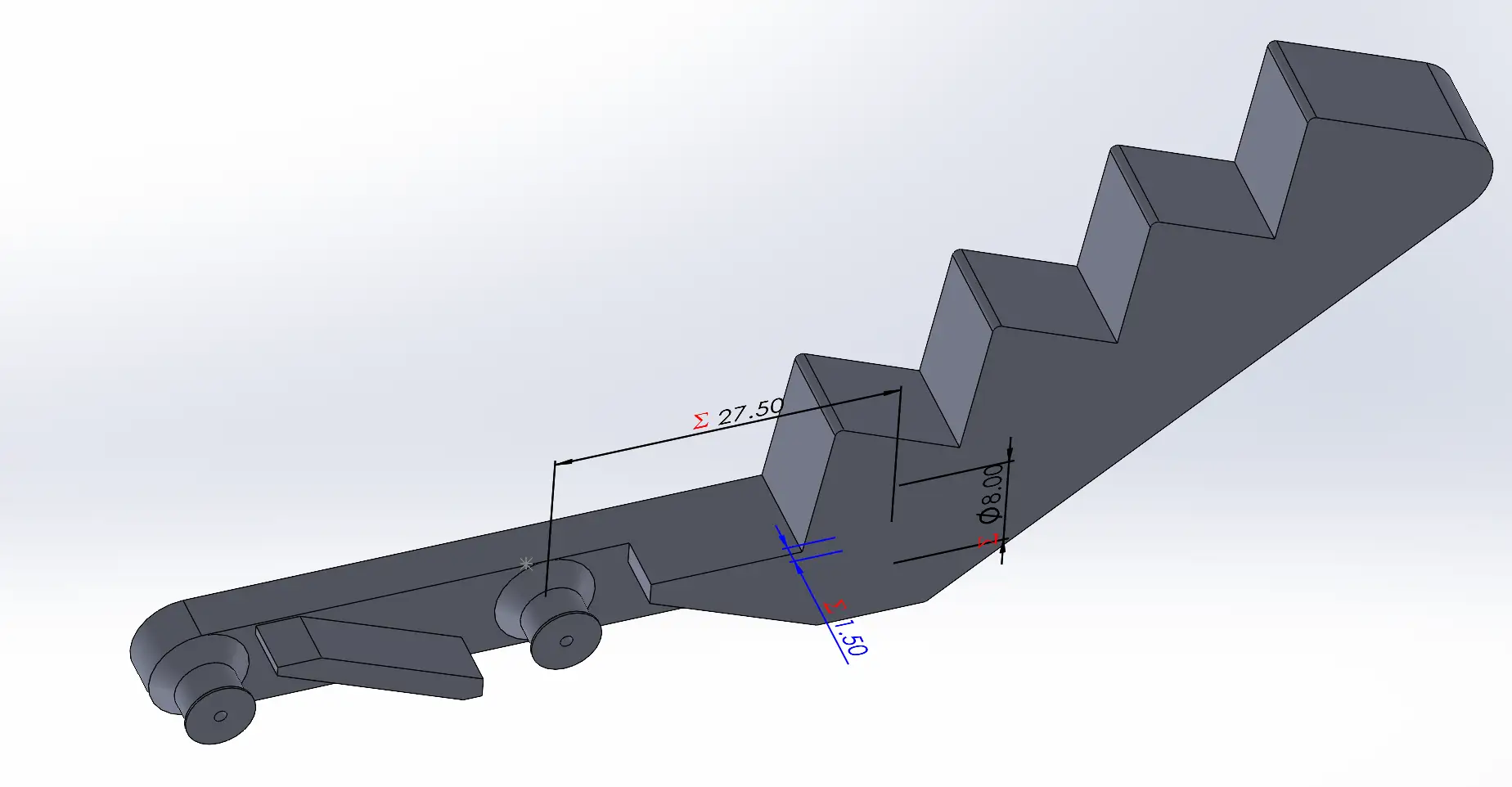
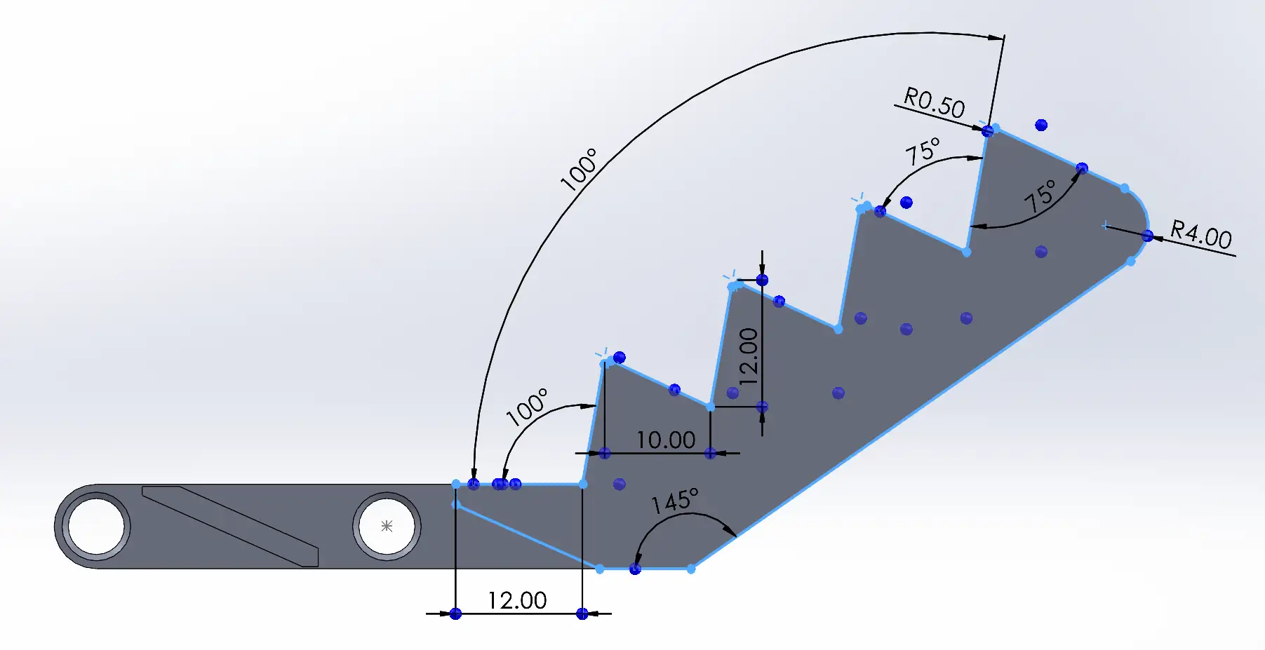
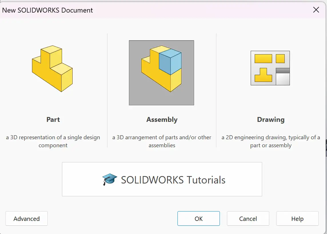
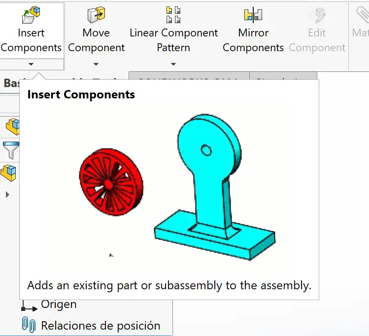
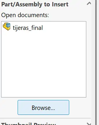
First, I created all the parts in SOLIDWORKS, ensuring that the dimensions and clearances were appropriate for 3D printing.
Extruder: Nextruder with a high-flow nozzle system
Key Feature: Automatic first-layer calibration via Load Cell sensor
Nozzle: 0.4 mm High-Flow
Slicer Software
PrusaSlicer
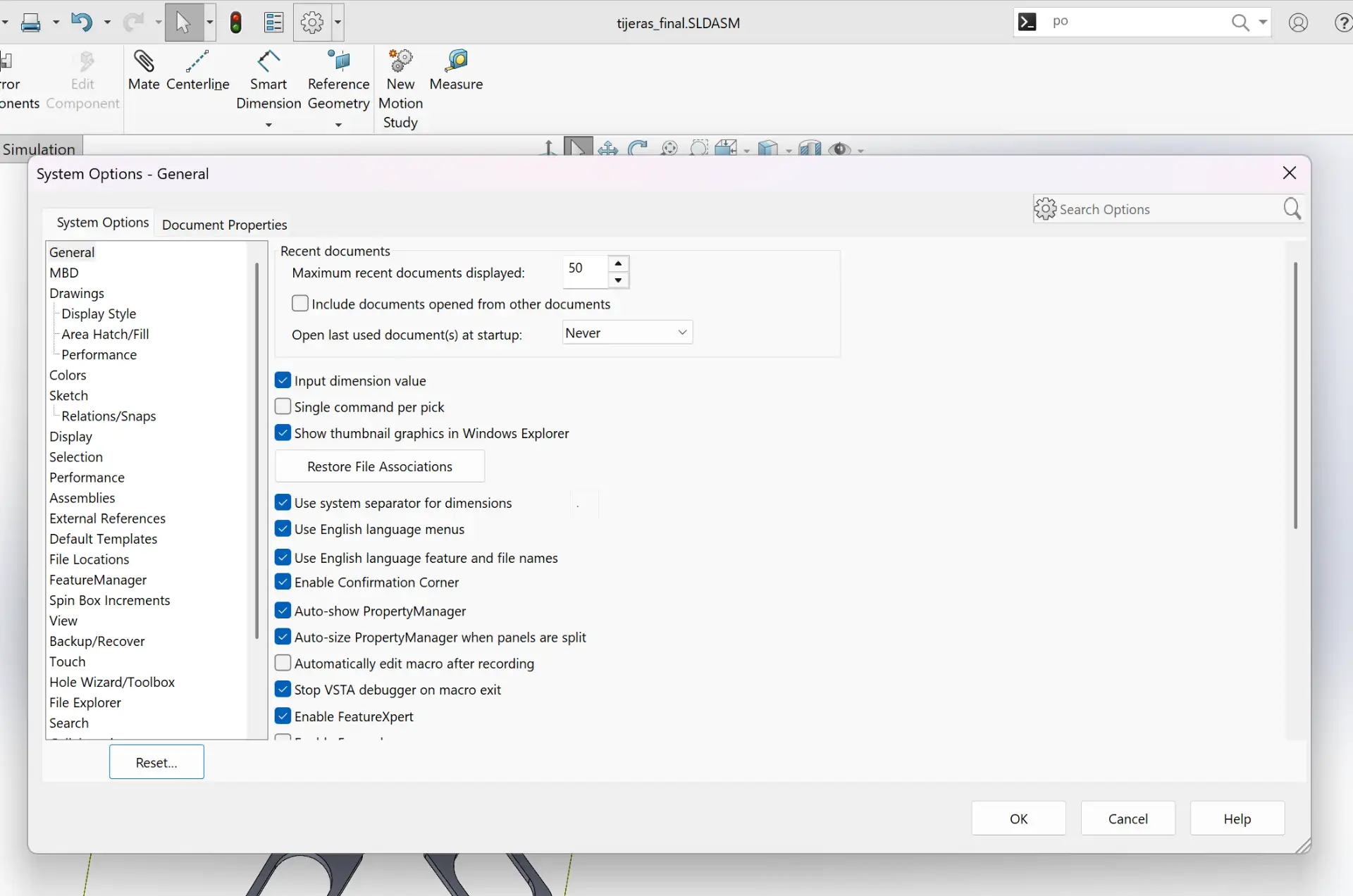
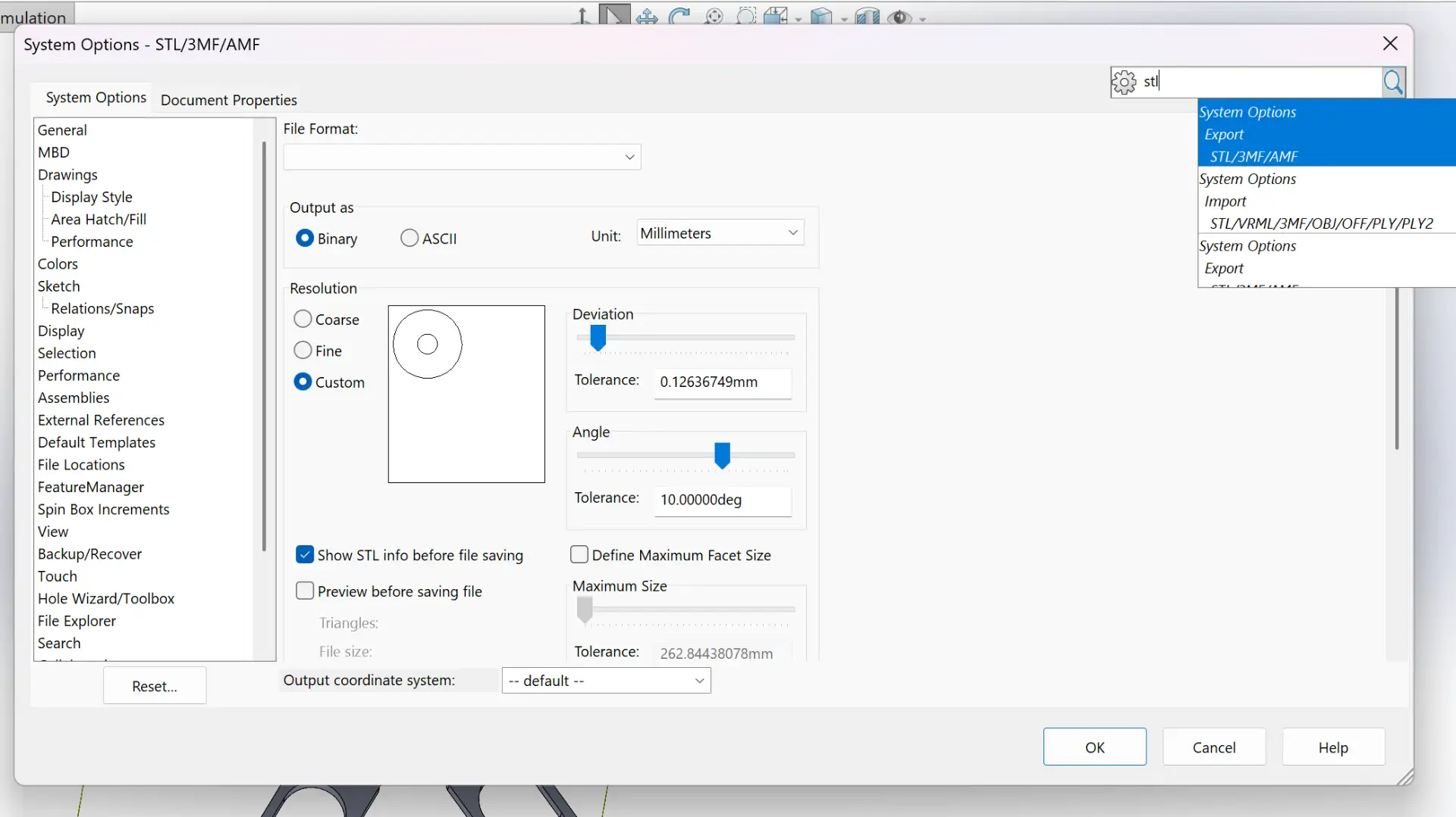
I used the PrusaSlicer to slice the STL file and generate G-code for 3D printing.
Printer
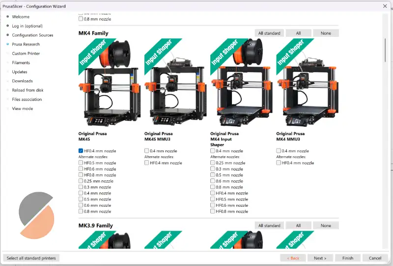
To choose the printer in PrusaSlicer, go to the "Configuration" > "Configuration Wizard" and go to Prusa Research to select your printer model.
I chose the model available in my FAB LAB: Original Prusa MK4S HF0.4 mm nozzle
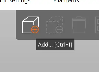
Add STL File
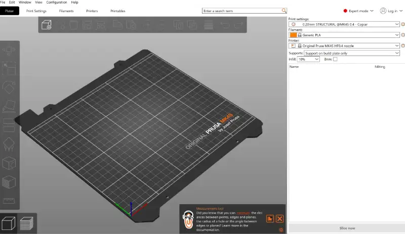
To add the STL file into PrusaSlicer, click on the cube icon in the top left corner of the interface.
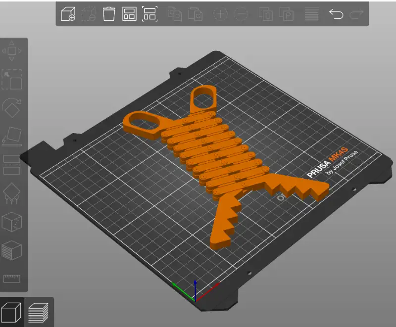
Plater
Once the STL file is added, it appears in the Plater section.
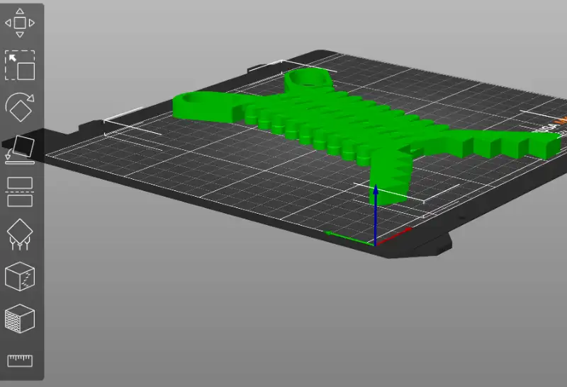
Tools
In the Tools section at the left, you can find many useful tools like scaling, rotating, position, measuring, and more.
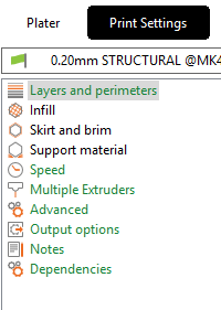
Print Settings
You can adjust print settings like layers, speed, infill density, support structures and more in the Print Settings section.
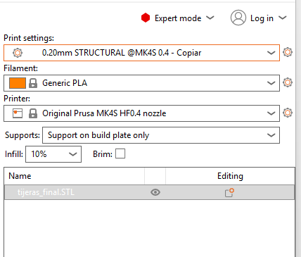
Right Panel Settings
The right panel contains fast settings like the type of filament, supports placement, infill, and other quick adjustments.
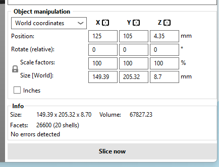
Slice
Once you have set all the necessary parameters, click on the "Slice now" button to generate the G-code for your 3D printer. Also in this section you can view the size and position of the model on the plater.
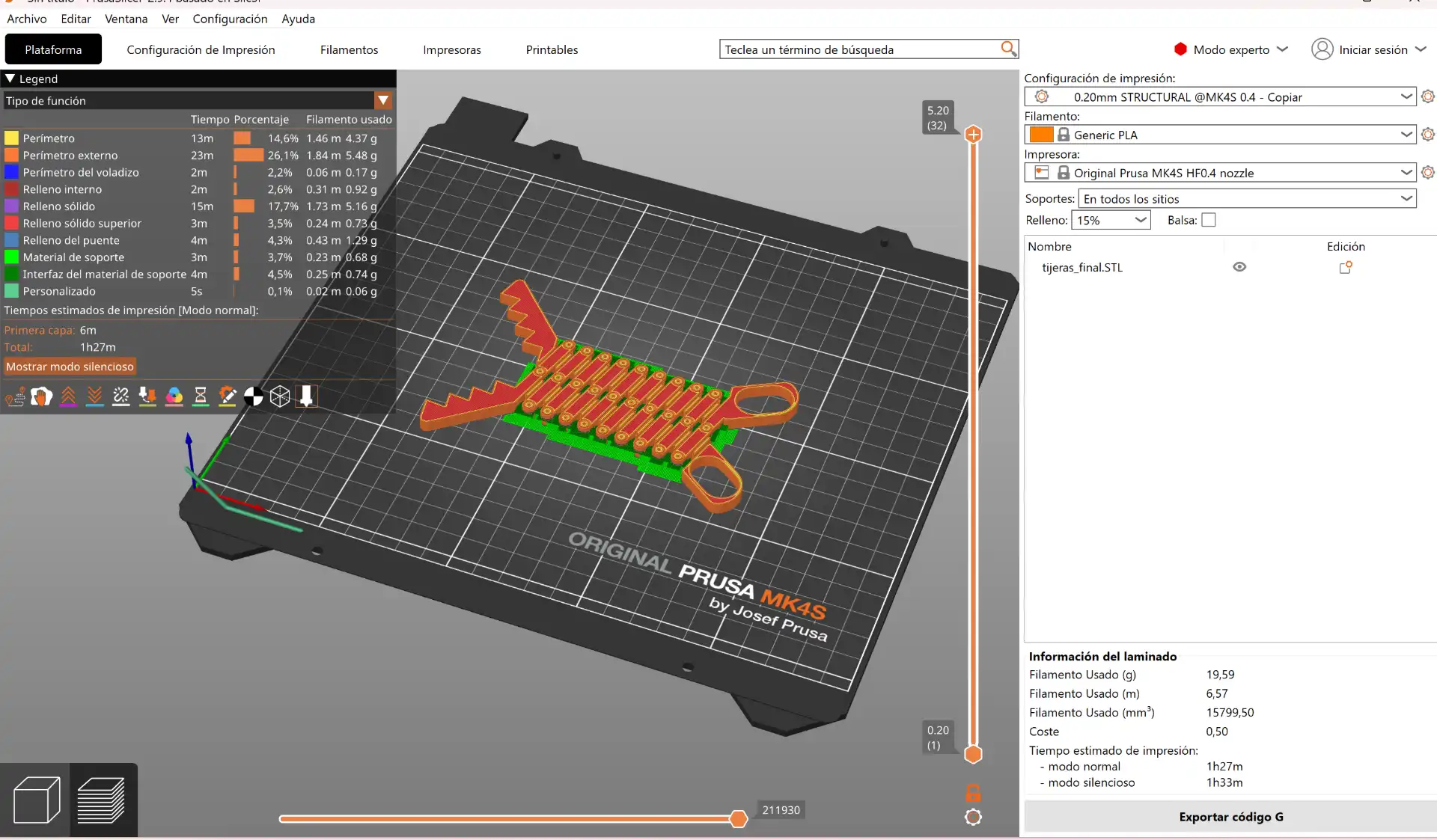
Final Result
After slicing, you can view the final look of your 3D model and the calculated print time and material usage.
After slicing the model, I transferred the G-code to the printer via USB, the most recent file will appear immediately on the screen, and started the printing process.
Fig 2. Print file
Fig 3. Final extending tongs
3D Scanning
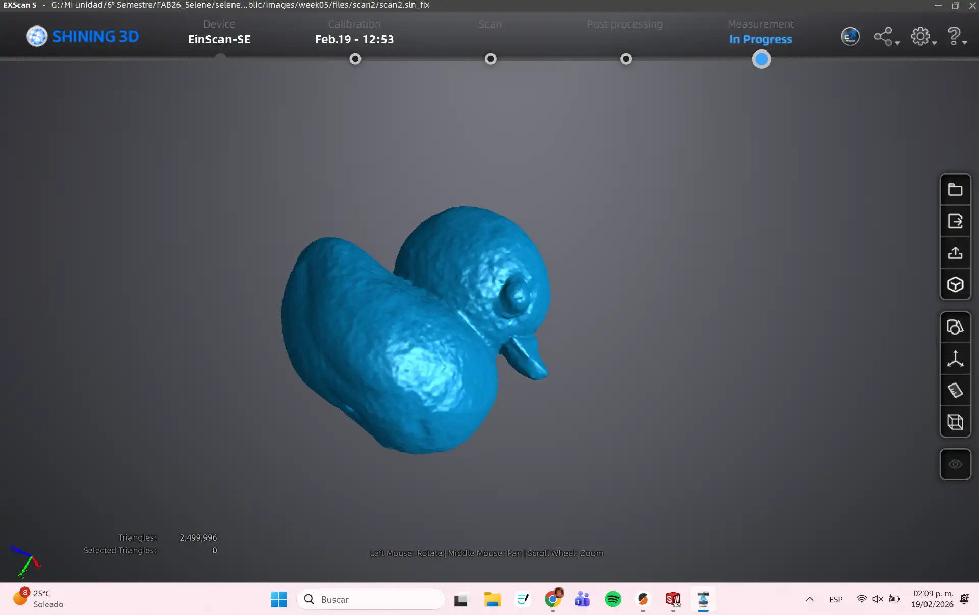
For this assignment, I used a structured light scanner to capture the geometry of a small duck. The scanning process involved projecting a series of light patterns onto the object and capturing the distortions with a camera. The resulting point cloud was then processed using software to create a 3D mesh, which was cleaned up and prepared for printing.
What is 3D Scanning?
3D scanning is the process of capturing the shape and appearance of a physical object and converting it into a digital 3D model. By using specialized sensors or cameras, the scanner collects data about the object's surface to create a "point cloud," which is then processed into a digital mesh.
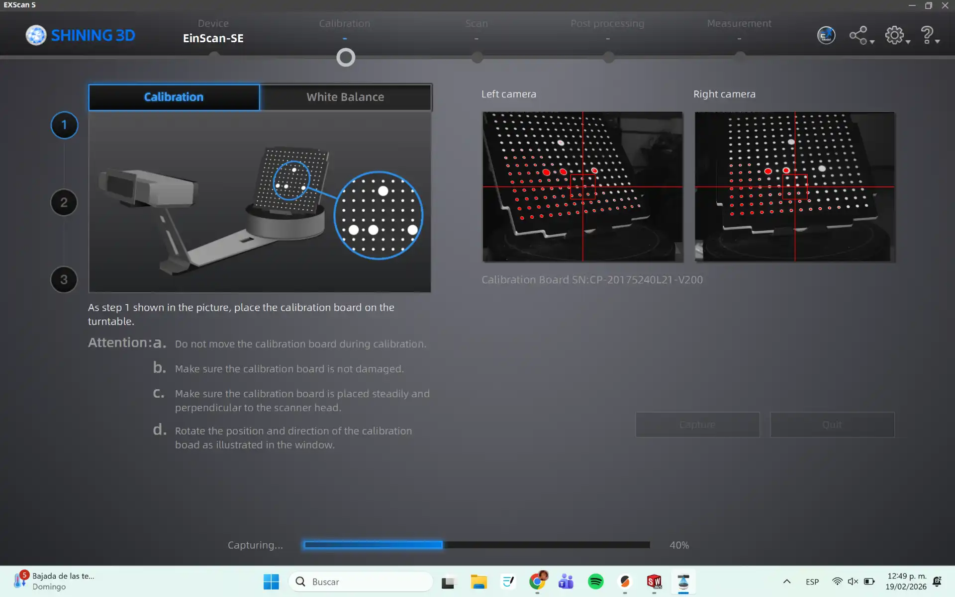
First, I calibrated the scanner using the calibration target provided with the EinScan SE. This step ensures accurate scanning results by aligning the scanner's coordinate system with the physical world.
Calibration Process
This is the calibration process, you need to follow the steps shown in the program until the calibration is complete.
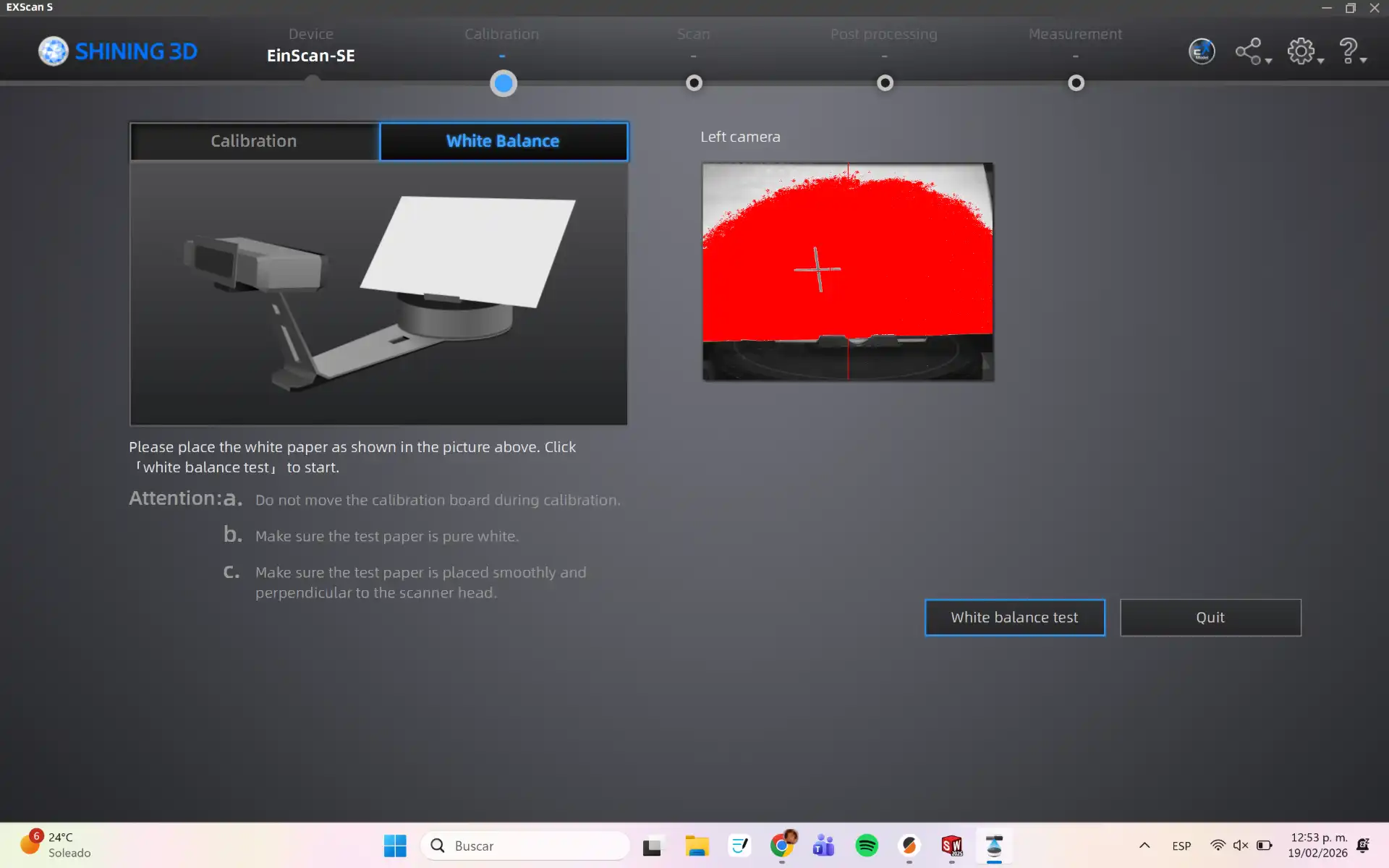
White Balance calibration
After calibration, the scanner needs to be white balanced. This step ensures that the scanner captures accurate colors and brightness levels.
White Balance Calibration Process
This is the white balance calibration process, you need to follow the steps shown in the program until the calibration is complete.
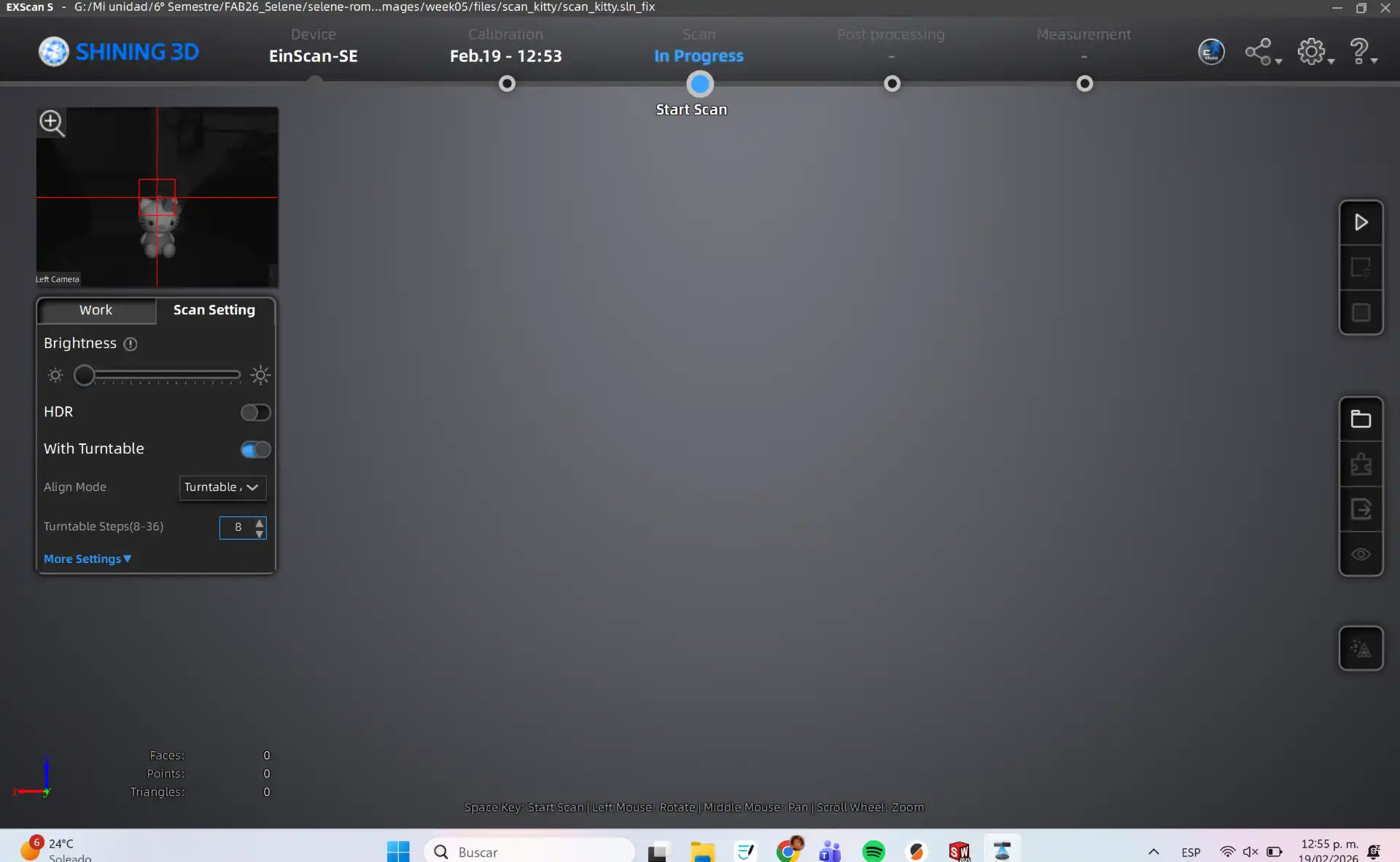
Main
After calibration you need to start a new project, select Non-Texture Scan. This is the main interface of the scanner software, where you can manage your scanning projects and access various tools.
Process
In the menu on the left you can adjust the brightness and the number of Turntable Steps. To start you need to push the Play Button.
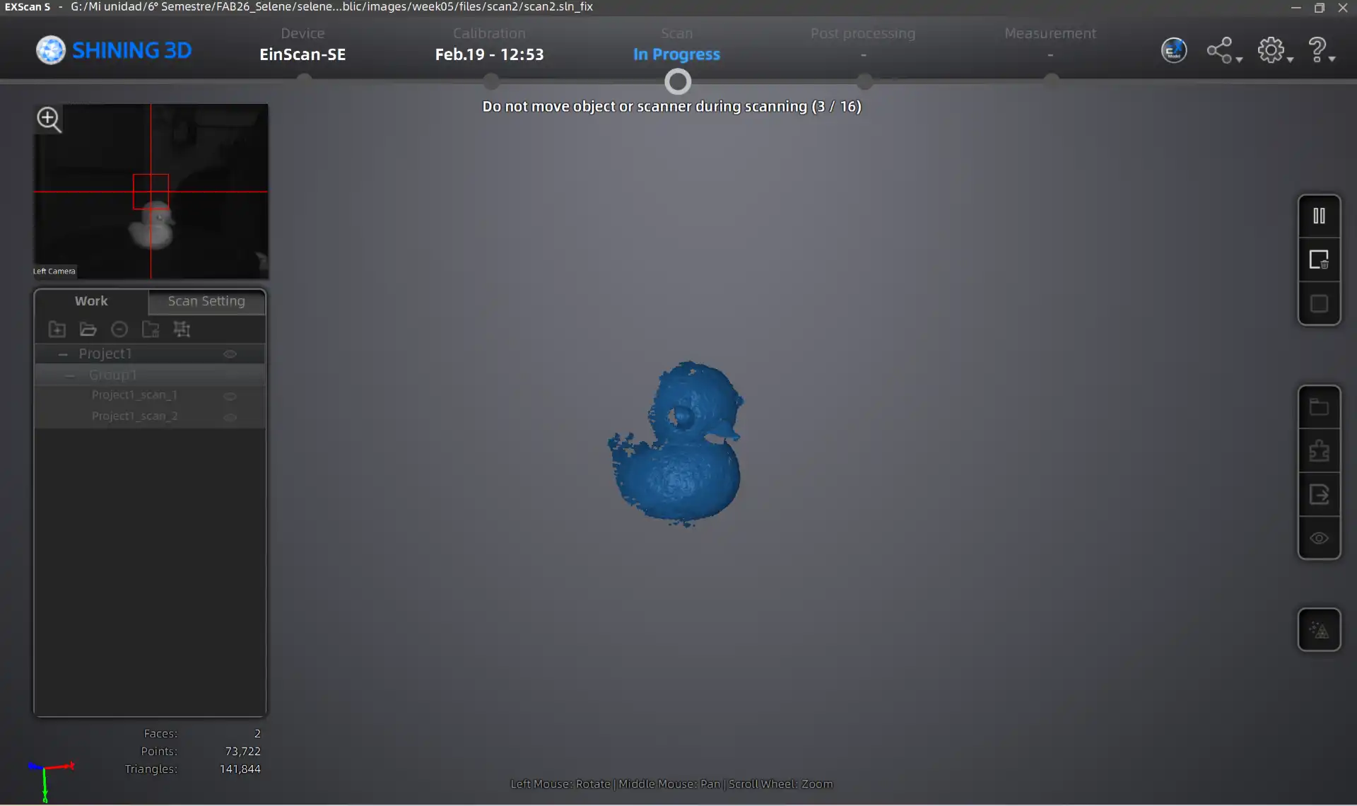
Final Scan Result
Once the turntable cycle is complete, you can perform additional scanning passes until the model is fully reconstructed.
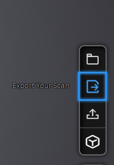
Export STL
After finalizing the scan, use the right-hand menu to refine the mesh with smoothing tools. Then, generate the STL output for your 3D printer's slicing software.
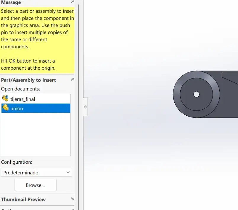
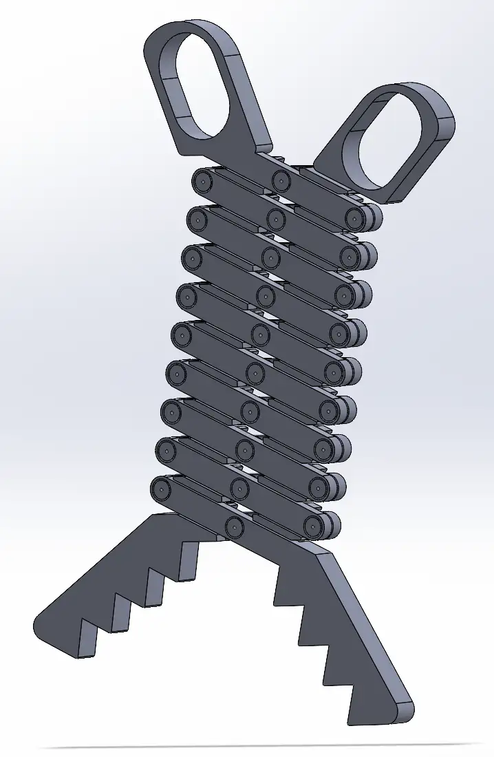 Fig 1. Final Assembly
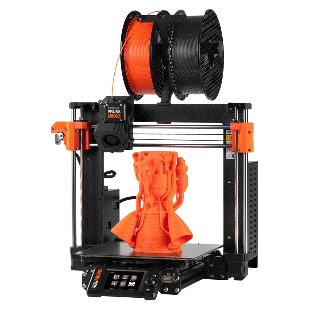
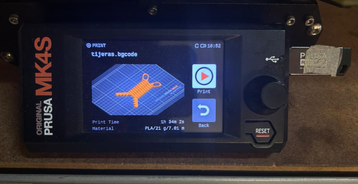 Fig 2. Print file
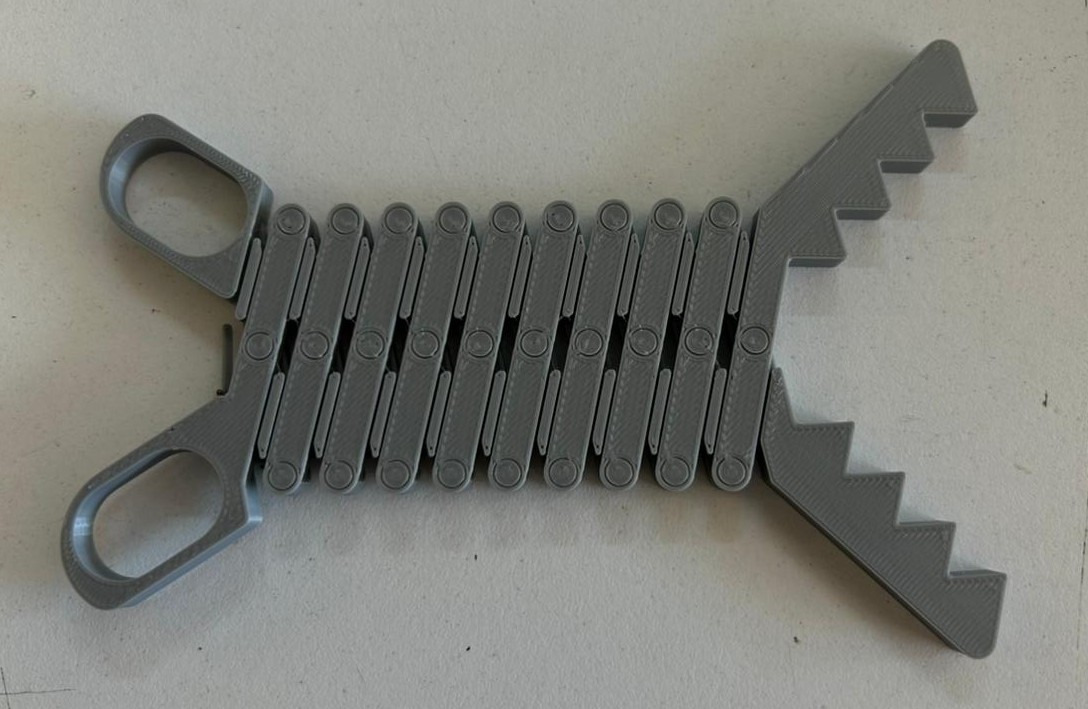 Fig 3. Final extending tongs
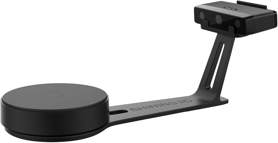
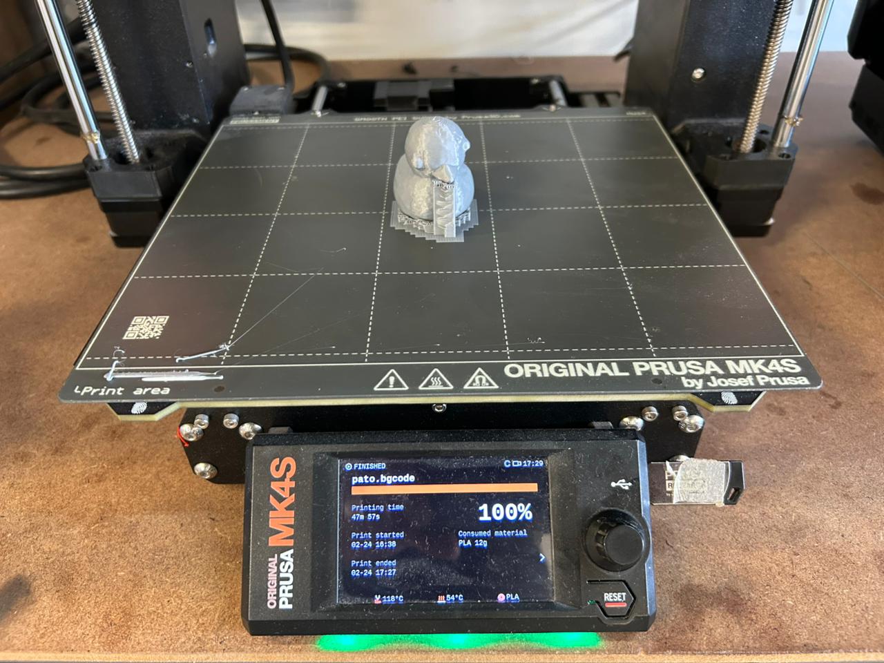 Fig 4. Final Print
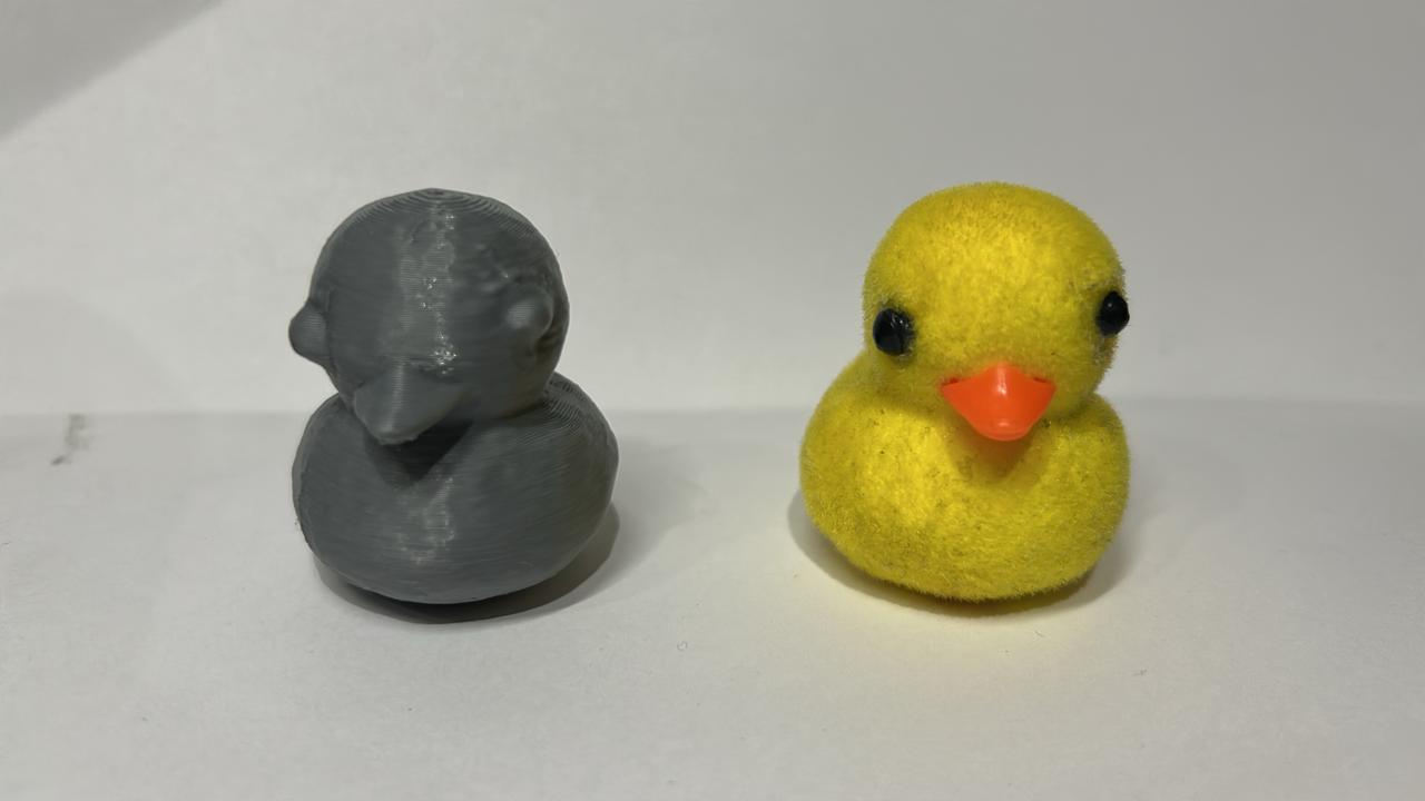 Fig 5. Final Duck