This week's directive is to "Make Something Big" using the CNC Router. I decided to design and build a custom wooden house for my dog. The challenge? It must be assembled entirely using press-fit joints, meaning no glue, no nails, and no screws allowed!
01. GROUP ASSIGNMENT
MISSION LOG: CNC MACHINE TESTING
Before cutting our final projects, the team tested the CNC router's runout, alignment, speeds, feeds, and toolpaths. We determined the exact tolerances needed for our press-fit joints in the plywood we are using.
Before jumping into CAD, I needed a concept. I wanted to design a dog house that wasn't just a boring traditional box, I wanted it to have personality and style. After sketching some ideas, I settled on a basic, geometric design without a door (My dog is a little fat jajajaja) so I could focus on the interlocking joints and the overall structure. I also wanted to make it modular, so I designed it in separate panels that could be easily cut and assembled.
PARAMETRIC MODELING & TOLERANCES
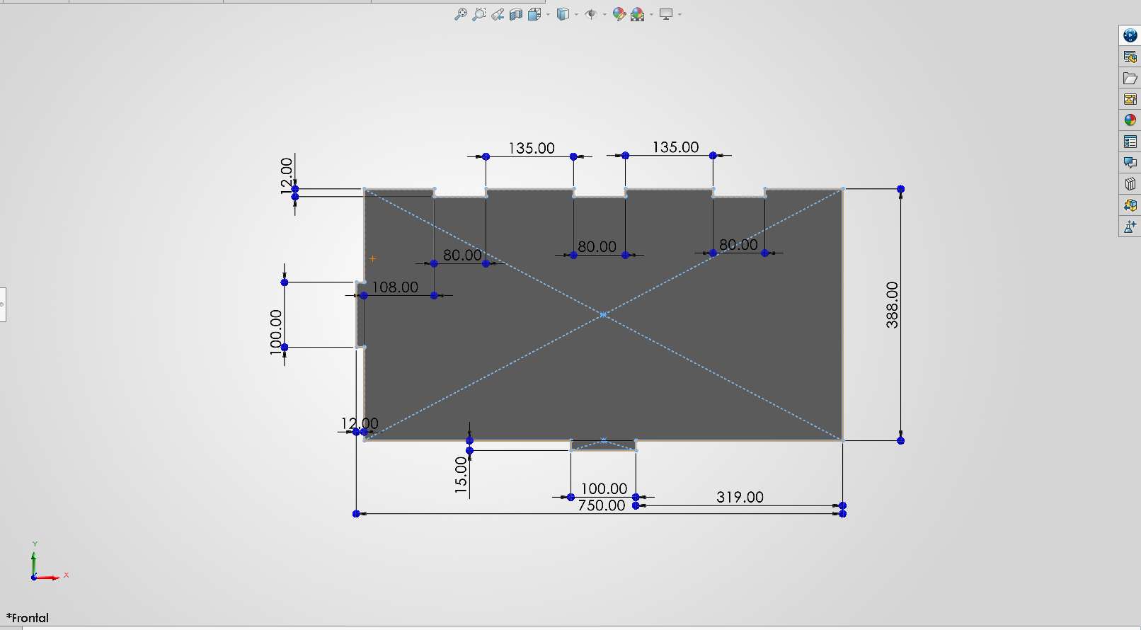
To ensure the house is structurally sound and easy to assemble, I modeled every piece parametrically in SolidWorks. Based on our group assignment, I set my material thickness parameter to 12mm. To compensate for the machine's runout and the material, we determined a tolerance/clearance of 0.2 mm was needed in the slots. This ensures a tight press-fit joint without splitting the wood.
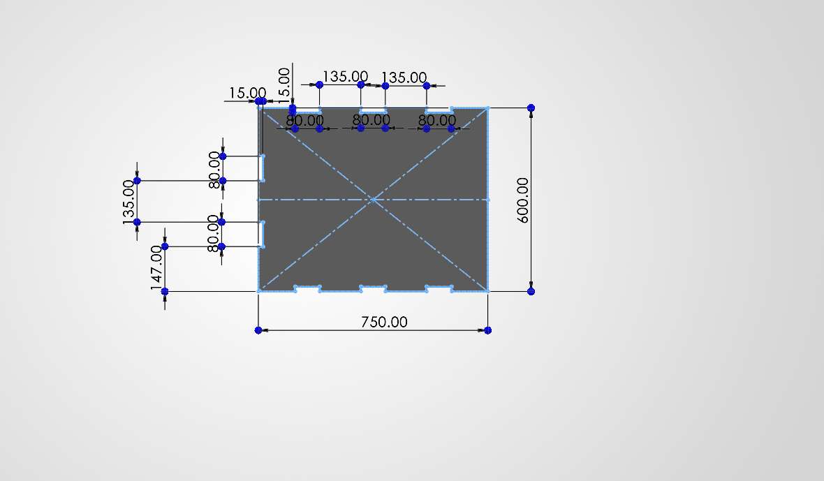
01. Starting the parametric sketches. designing the floor.
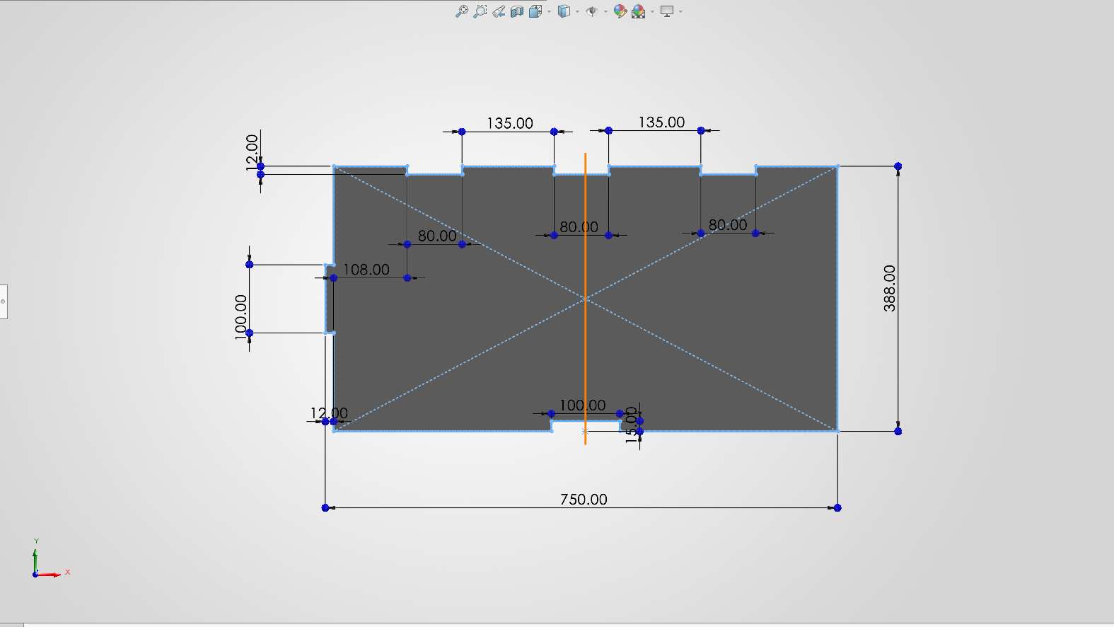
02. Extruding the main walls.
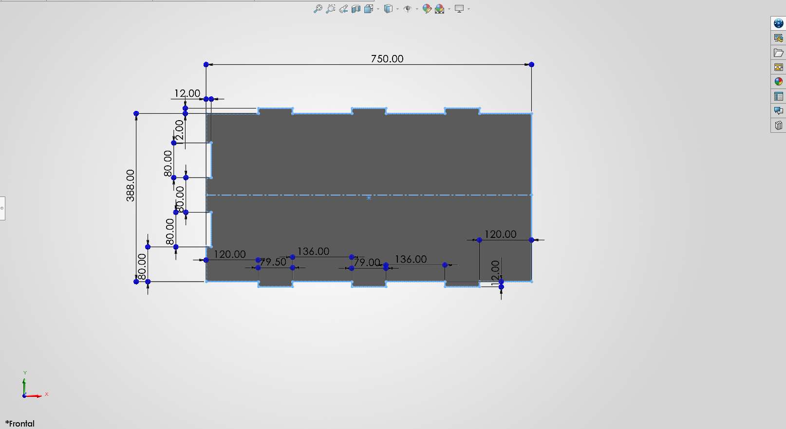
03. Designing the back wall with press-fit joints.
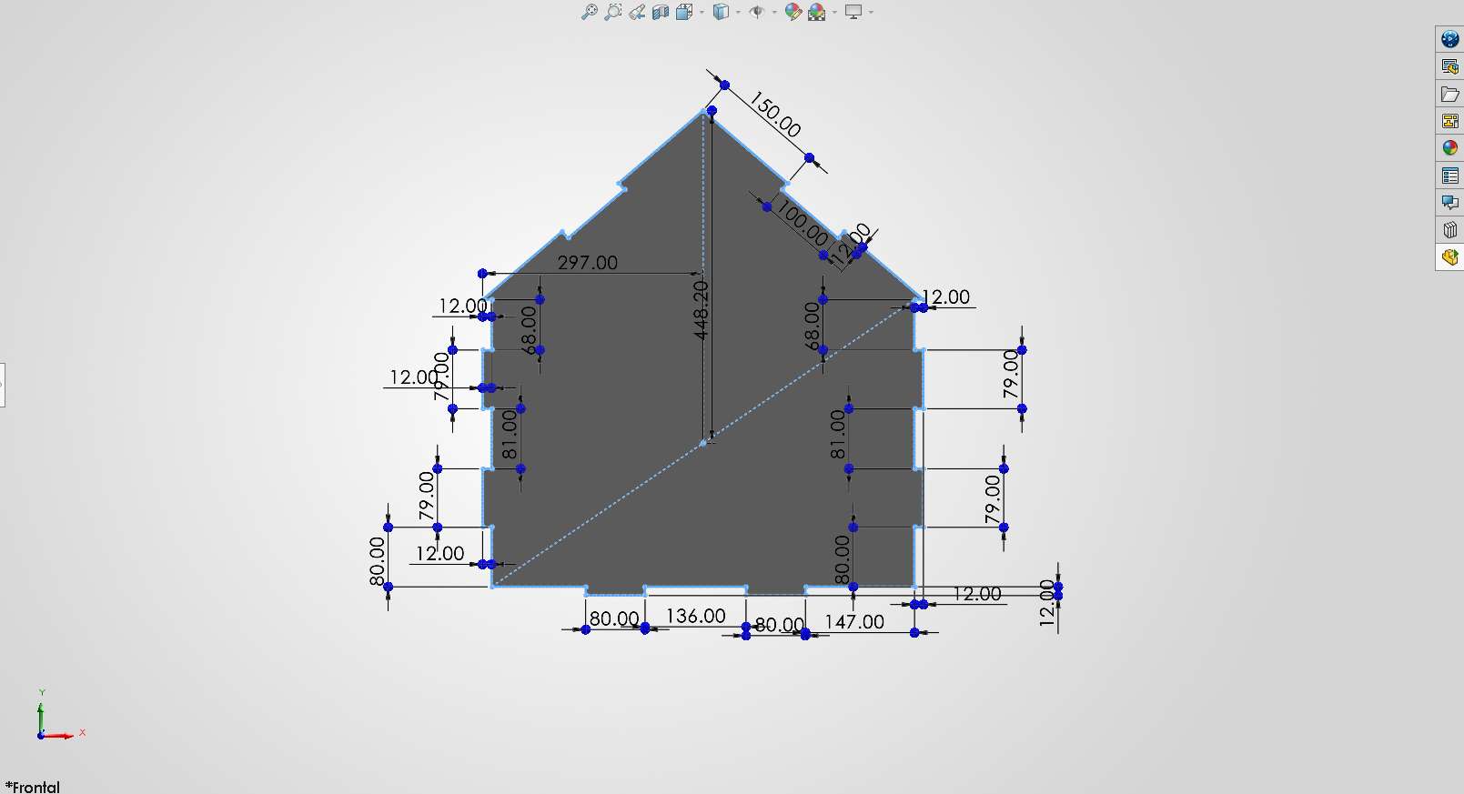
04. First roof panel.
05. Second roof panel.
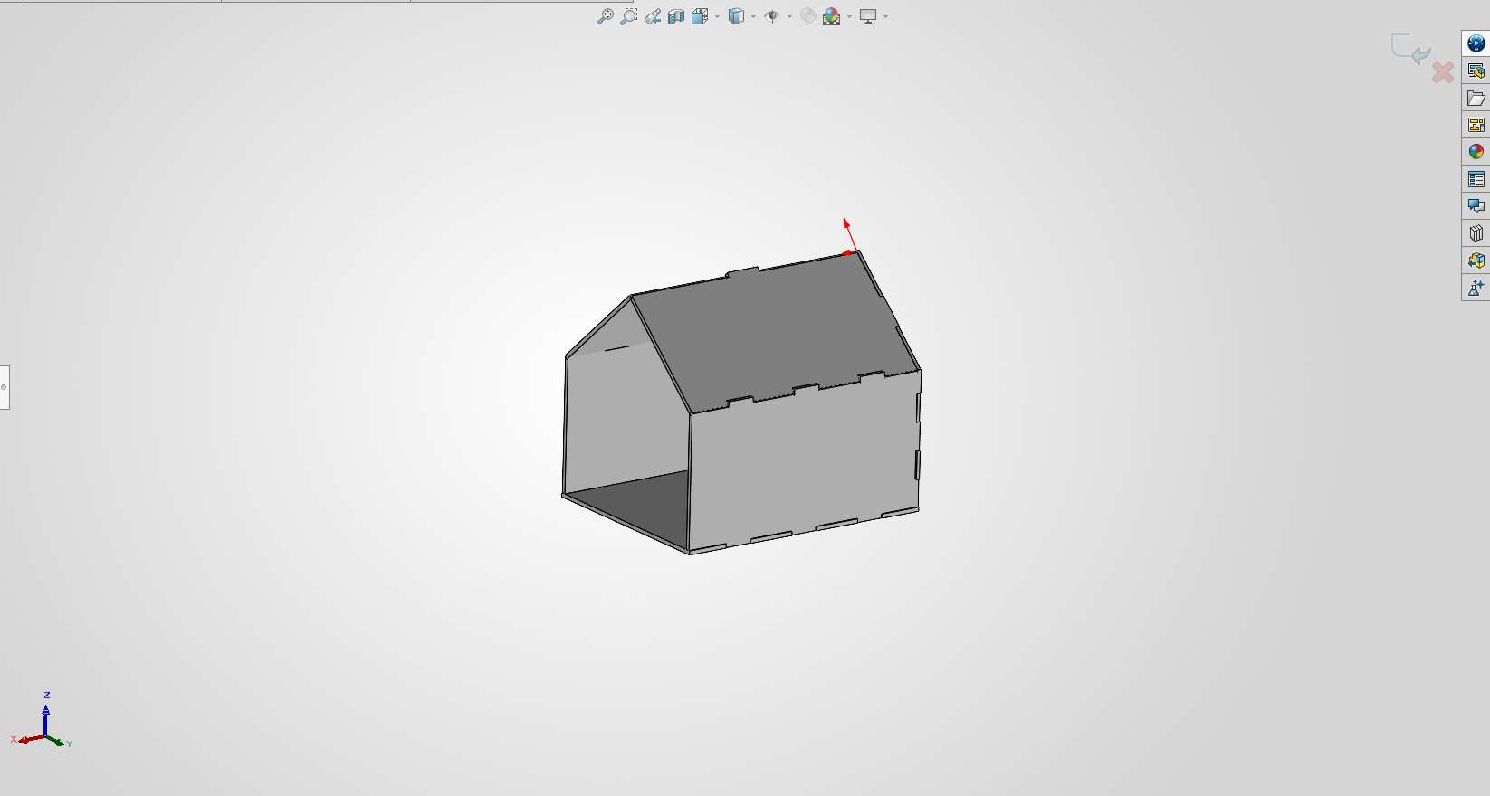
06. The complete 3D assembly in SolidWorks before exporting to DXF.
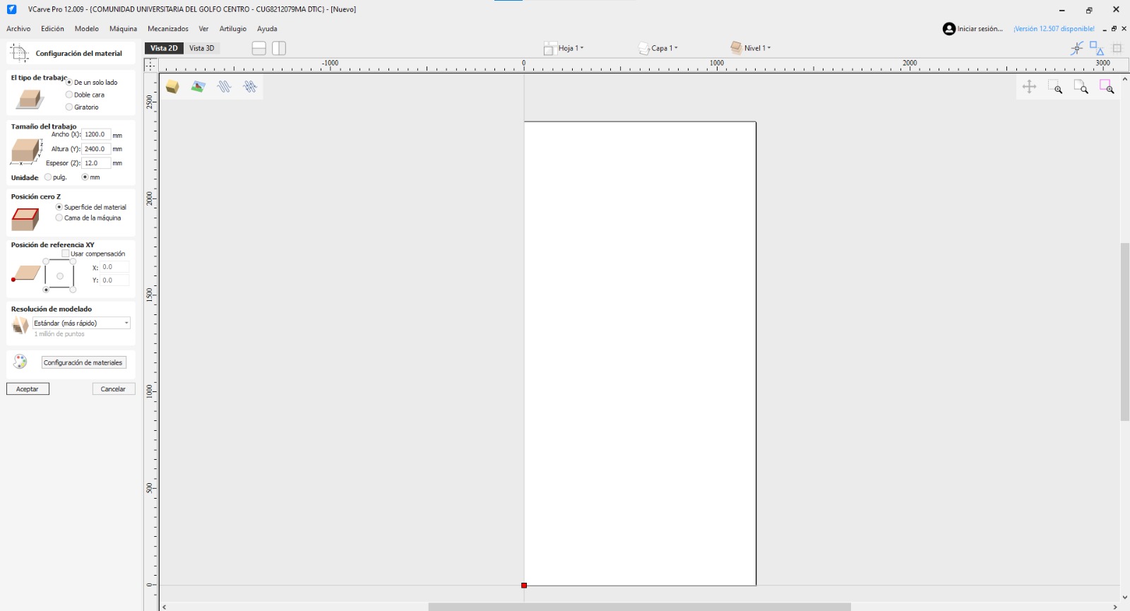
This is VCarve, the software used for this week.
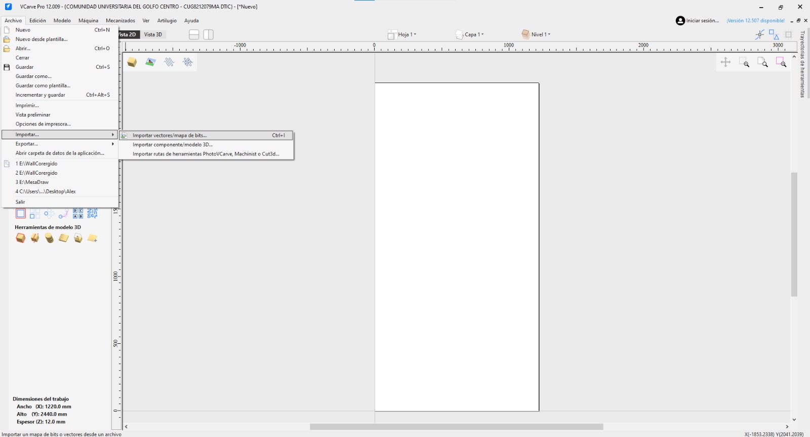
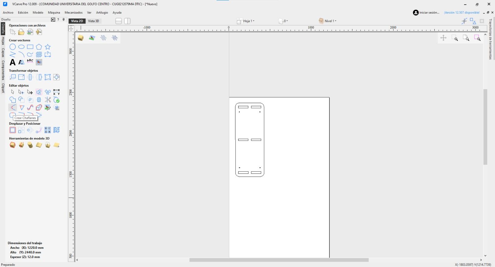
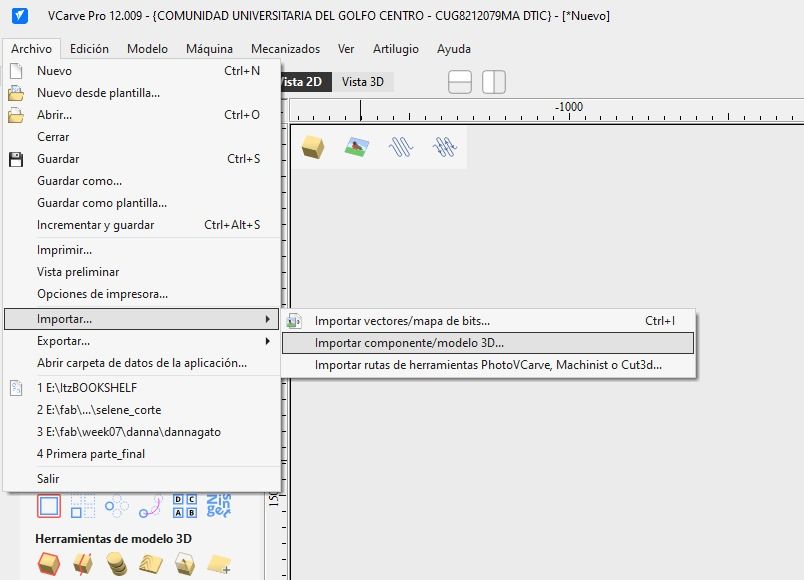
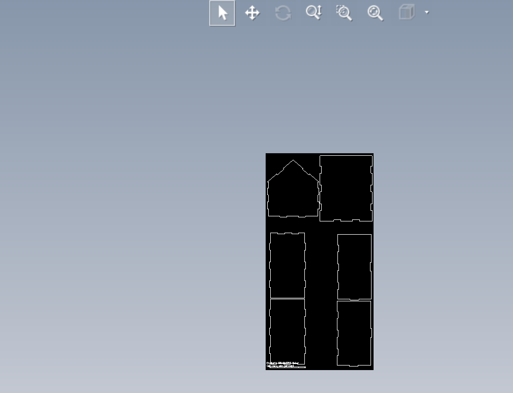
Importing the DXF files into VCarve.
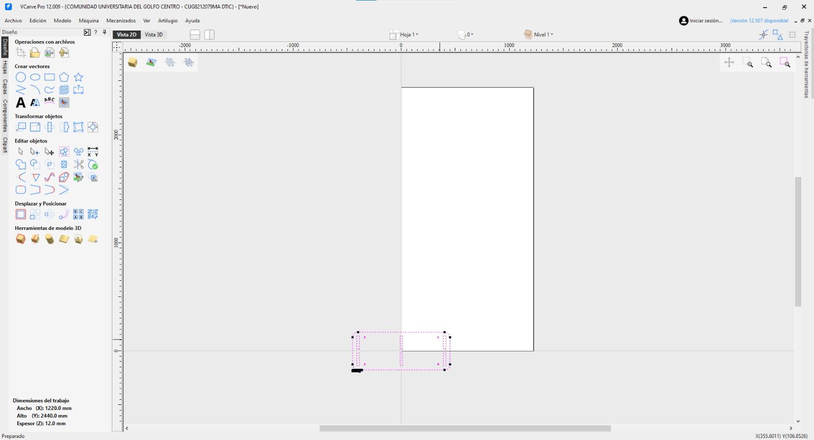
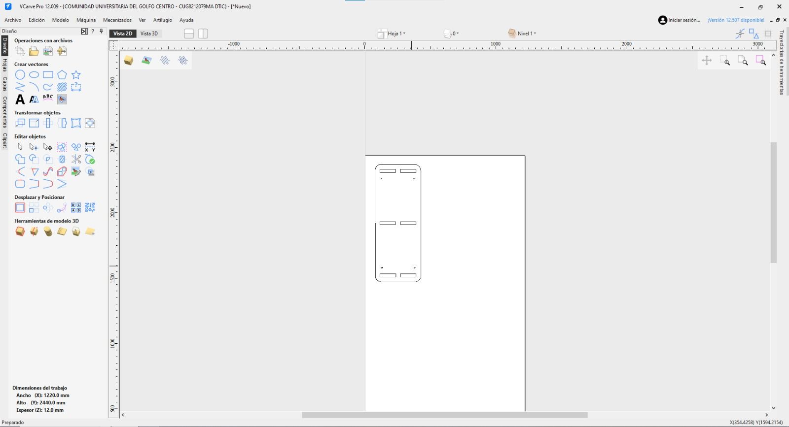
Placing the shapes in the VCarve workspace.
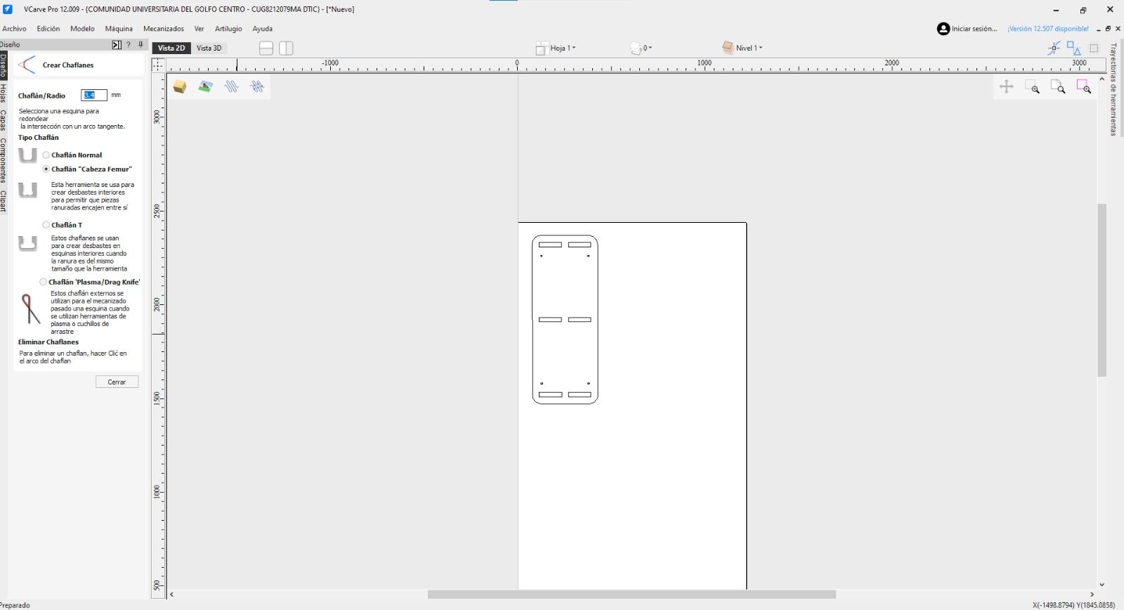
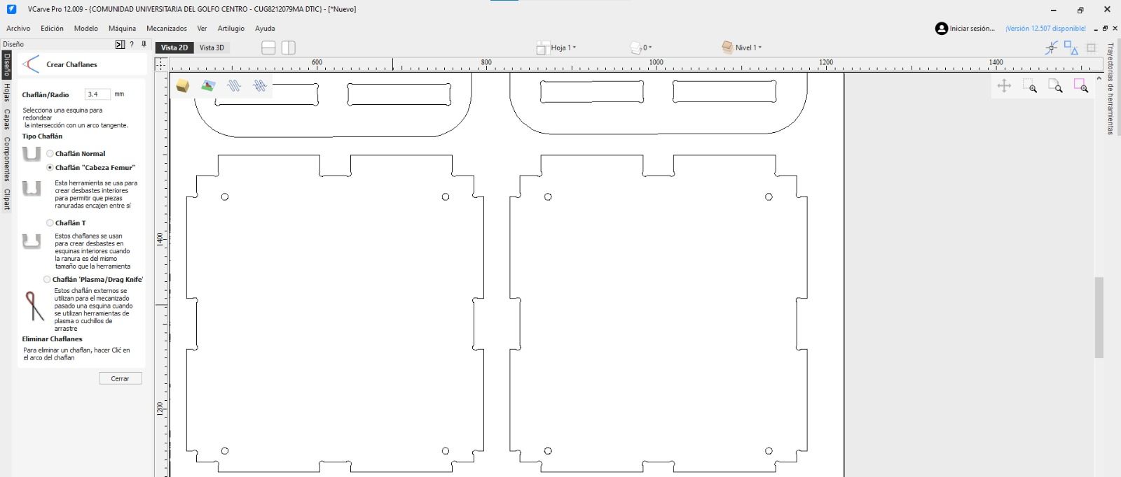
THE SECRET WEAPON: DOG-BONES
Because a round CNC bit cannot cut a perfectly sharp 90-degree internal corner, I applied a "dog-bone" technique on the inner corners. Using a 1/4 inch endmill, I created fillets with a radius slightly larger than 3.175mm. This ensures the interlocking pieces fit perfectly flush without manual filing.
1 / 3
01. Sketching the Dog-bone fillets at the corners of the joint.
02. Applying the dog-bone technique cut to the 3D model.
03. The joints are fully prepped for machining. No hand-filing needed later!
03. CAM & TOOLPATHS (VCARVE SETUP)
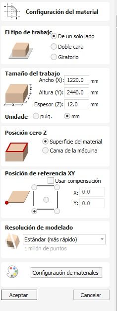
STOCK SETUP & MEASUREMENT
The first critical step in VCarve is the Stock Setup. I measured my plywood sheet with digital calipers in multiple spots to confirm the true thickness. I set my X/Y Origin to the bottom-left corner and the Z-Zero to the top of the material surface.
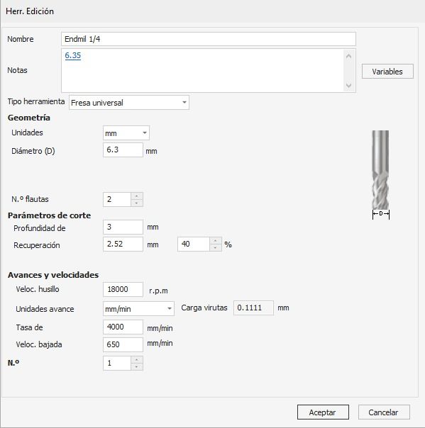
TOOL SELECTION & MACHINING PARAMETERS
I selected a 1/4 inch Flat Endmill. Based on our group assignment tests, I applied the following cutting data to avoid burning the wood or breaking the bit:
Spindle Speed: 18,000 RPM
Feed Rate: 2,500 mm/min (100 inches/min)
Plunge Rate: 750 mm/min (30 inches/min)
Pass Depth: 3.8 mm per pass
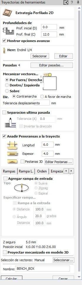
TOOLPATH STRATEGY
I divided the job into specific toolpaths:
Inside Cuts: Used for the windows and doors. The bit cuts inside the vector line so the hole is the exact right size.
Outside Cuts: Used for the perimeter of the pieces. The bit cuts outside the line so the final piece keeps its true dimensions.
Tabs (Fixing): Crucial! I added 3D tabs of 3mm length and 3mm thickness to the outside cuts. This keeps the pieces attached to the main board so they don't fly out and hit the router bit.
1 / 7
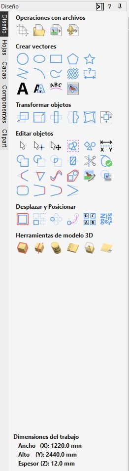
01. Starting a new file in VCarve and defining the material dimensions.
02. Importing the DXF files generated from SolidWorks.
03. The imported vectors placed on the digital canvas.
04. Opening the Toolpaths menu on the right side.
05. Selecting the correct endmill (router bit) from the tool database.
06. Setting the cutting parameters: depth, passes, feeds, and speeds.
07. Calculating the toolpaths before moving to the 3D simulation.
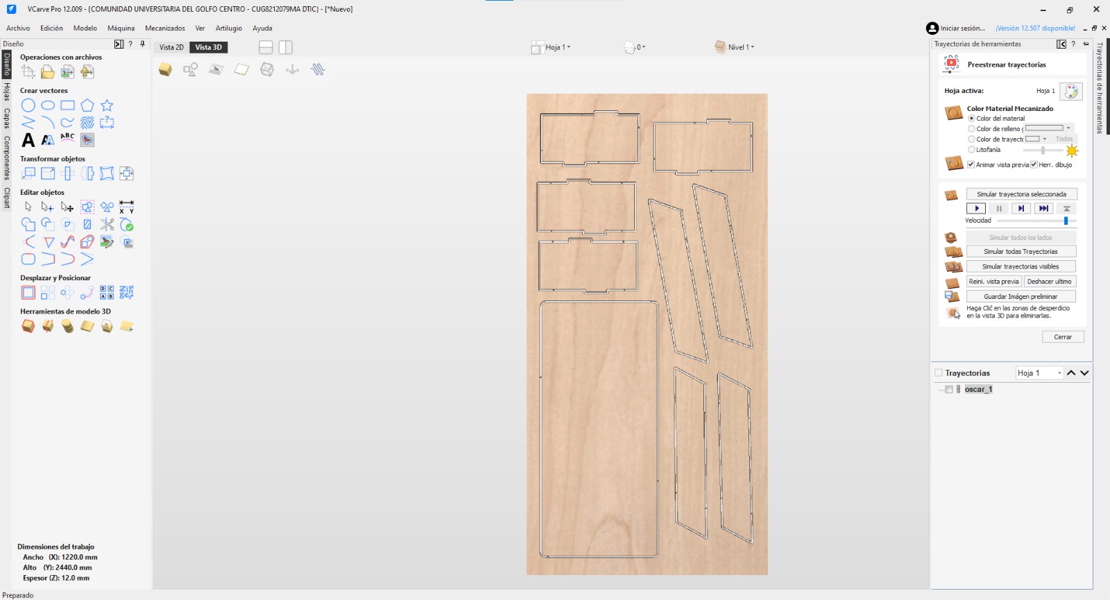
Simulating the toolpaths before cutting, I used example files.
This is how it is supposed to look.
04. MACHINING & CALIBRATION
Time for the heavy machinery! Before running any code, the stock must be completely rigid. We secured the large plywood board to the sacrificial CNC bed using wood screws around the outer edges and in the empty spaces between the pieces. I double-checked the toolpath simulation to make absolutely sure the router bit would never crash into a metal screw.
SETTING XYZ ZEROS
Operating the CNC requires a strict calibration protocol:
X & Y Axis: Using the control interface, I manually jogged the spindle to the bottom-left corner of my stock and zeroed the X and Y coordinates to match my VCarve setup.
Z Axis: I jogged the machine to the center of the board. To get an accurate Z-zero, we used the "paper trick". I lowered the spinning bit step-by-step until it just barely grabbed a piece of paper placed on the wood. I set Z to zero there.
Finally, we turned on the dust collector, loaded the G-Code, hit start, and stayed close to the emergency stop button!
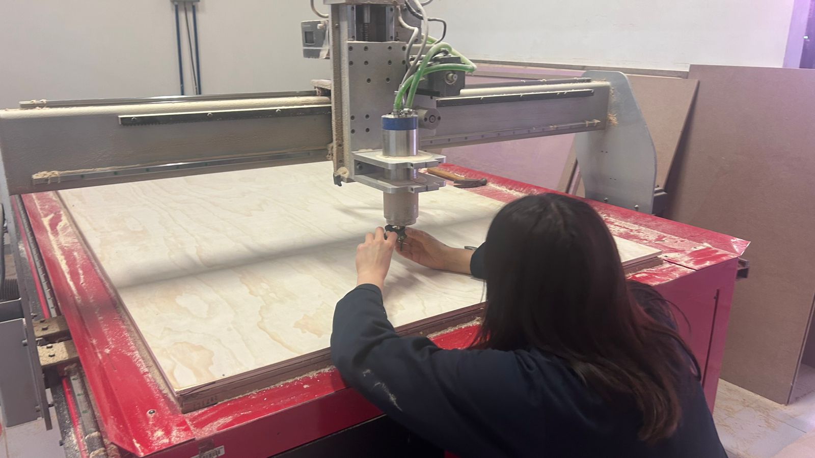
01. First of all we had to change the tool.
1 / 2
02. Calibrating the X and Y axes to set our starting origin point.
03. Carefully touching off the endmill to calibrate the Z axis (height).
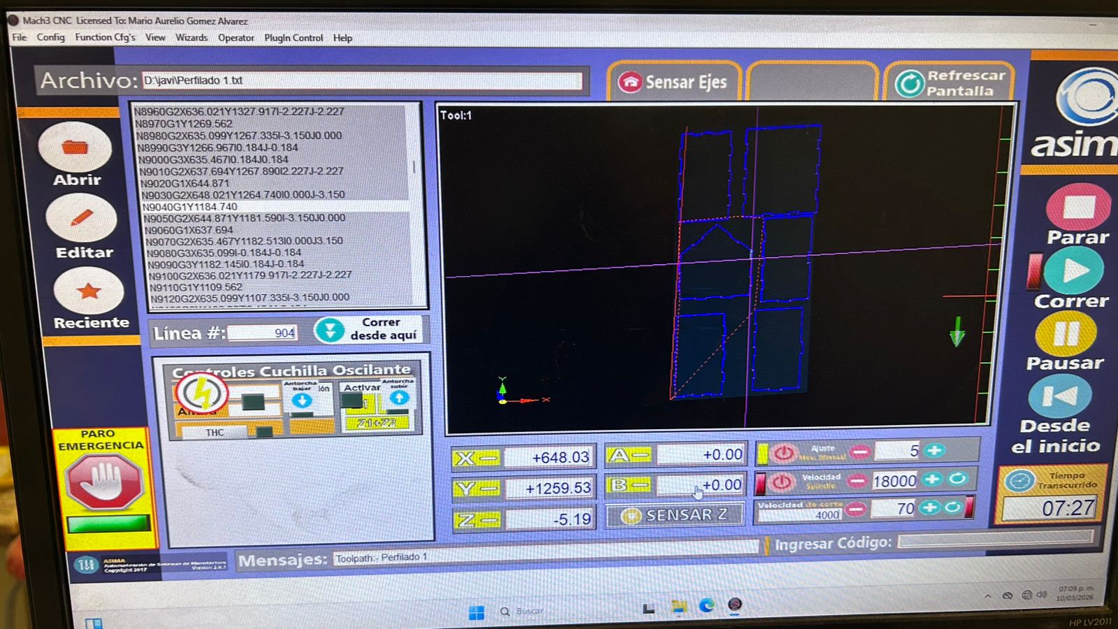
04. This is how I ordered the pieces in the control software.
05. Video: CNC Router executing the final cuts.
05. SANDING, ASSEMBLY & VARNISHING
After the CNC finished, the manual labor started. Removing tabs, sanding every edge to prevent splinters, assembling the press-fit structure, and applying varnish to protect the dog fortress from the weather. Here is the full process compiled:
01. Video: Sanding the edges.
02. Full process: testing press-fit tolerances, assembling with a rubber mallet, and varnishing the wood.
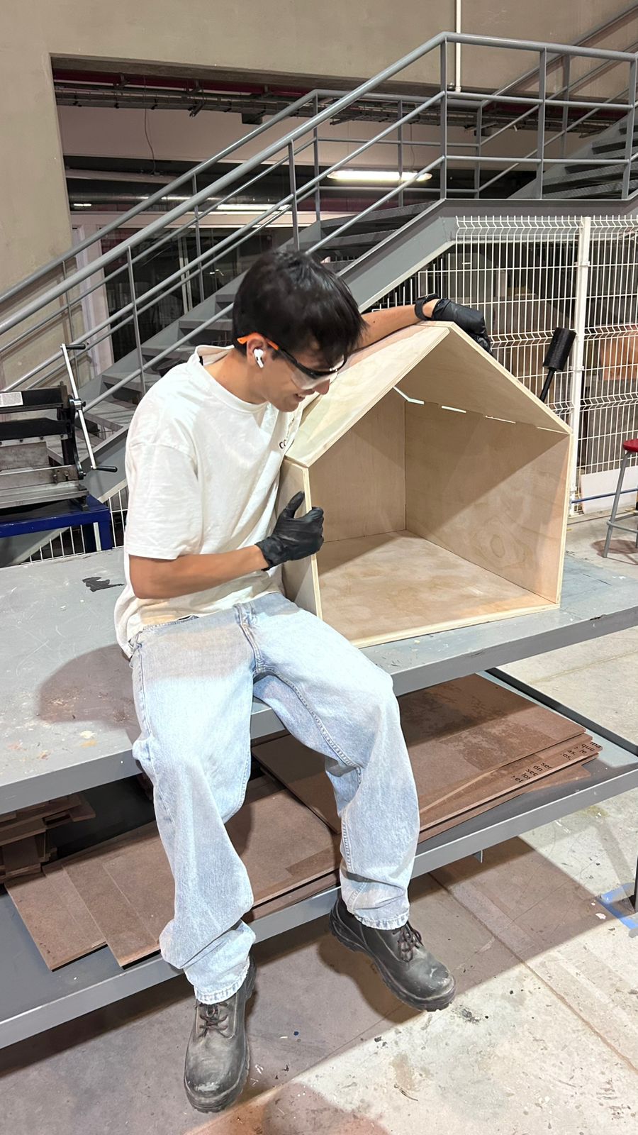
03. Sitting next to the fully assembled structure to show the real scale of the project!
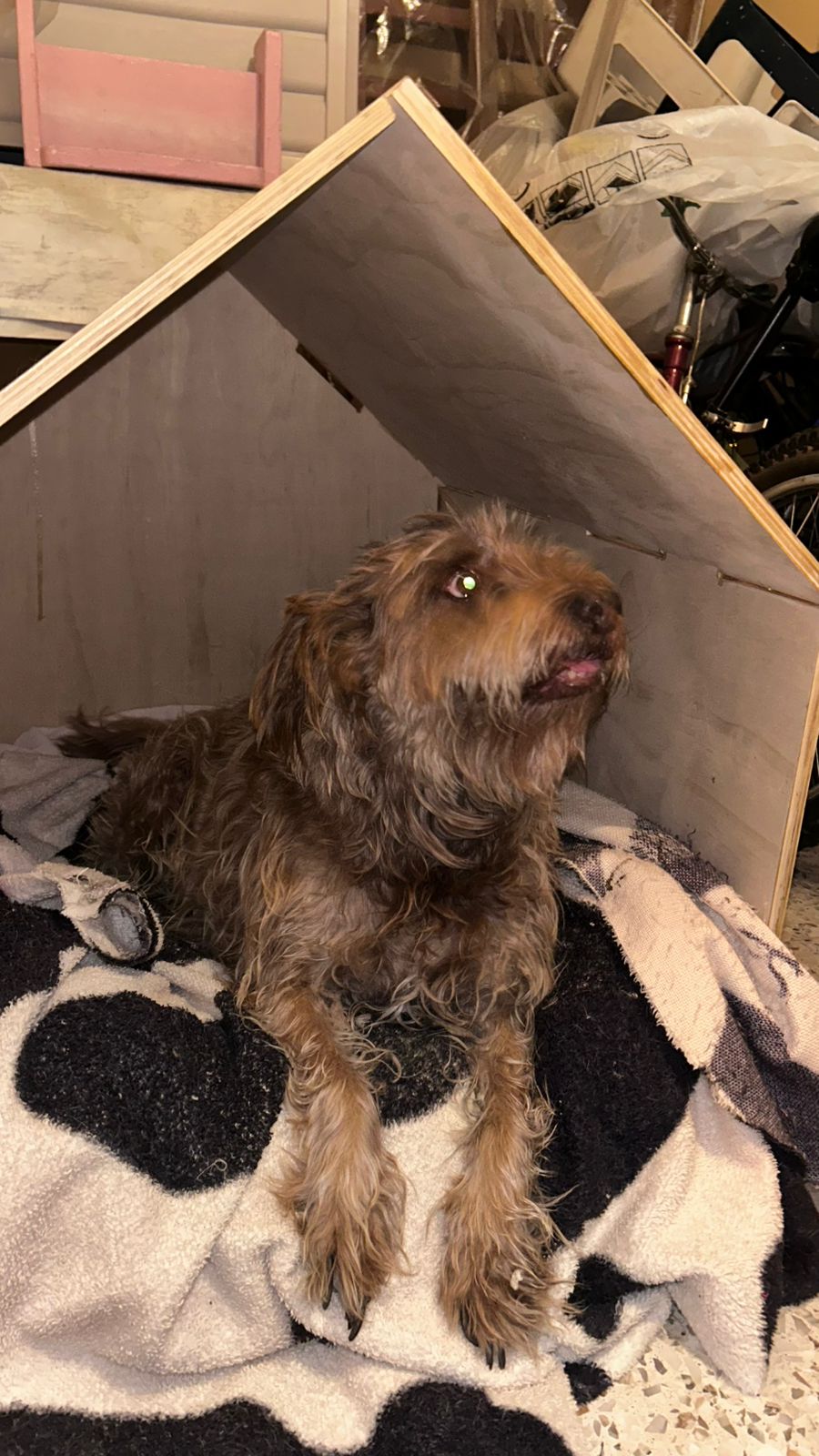
06. THE FINAL HERO PIECE
The dog fortress is complete! The structure is incredibly rigid thanks to the tight tolerances of the press-fit joints, and most importantly, the client approves of the final result.
The completed CNC Dog House. Mission Accomplished!