Group assignment
Objective
-
Send a message between two projects Document your work to the group work page and reflect on your individual page what you learned
Here I share the link to my group assignment.
Indivual assignment
- design, build and connect wired or wireless node(s) with network or bus addresses and a local input and/or output device(s).
What I know
I have previously worked with Arduino boards, but I have never worked with the communication aspect, such as connecting two boards to interact with each other so that one can trigger an action on the other. This will be my first experience.
In Week 08, I manufactured a PCB board that I will be using this week. Additionally, in Week 09, I worked with an input device, specifically a flex sensor. In that week, it can be observed that I used the board fabricated in Week 08. During Week 10, I worked with an output device, in this case, a DC motor. I am summarizing all the work I have done because these weeks are connected. All these devices are part of the development and testing process for my final project. Therefore, for networking and communication, I will use the board fabricated in Week 08, the input device from Week 09, and the output device from Week 10.
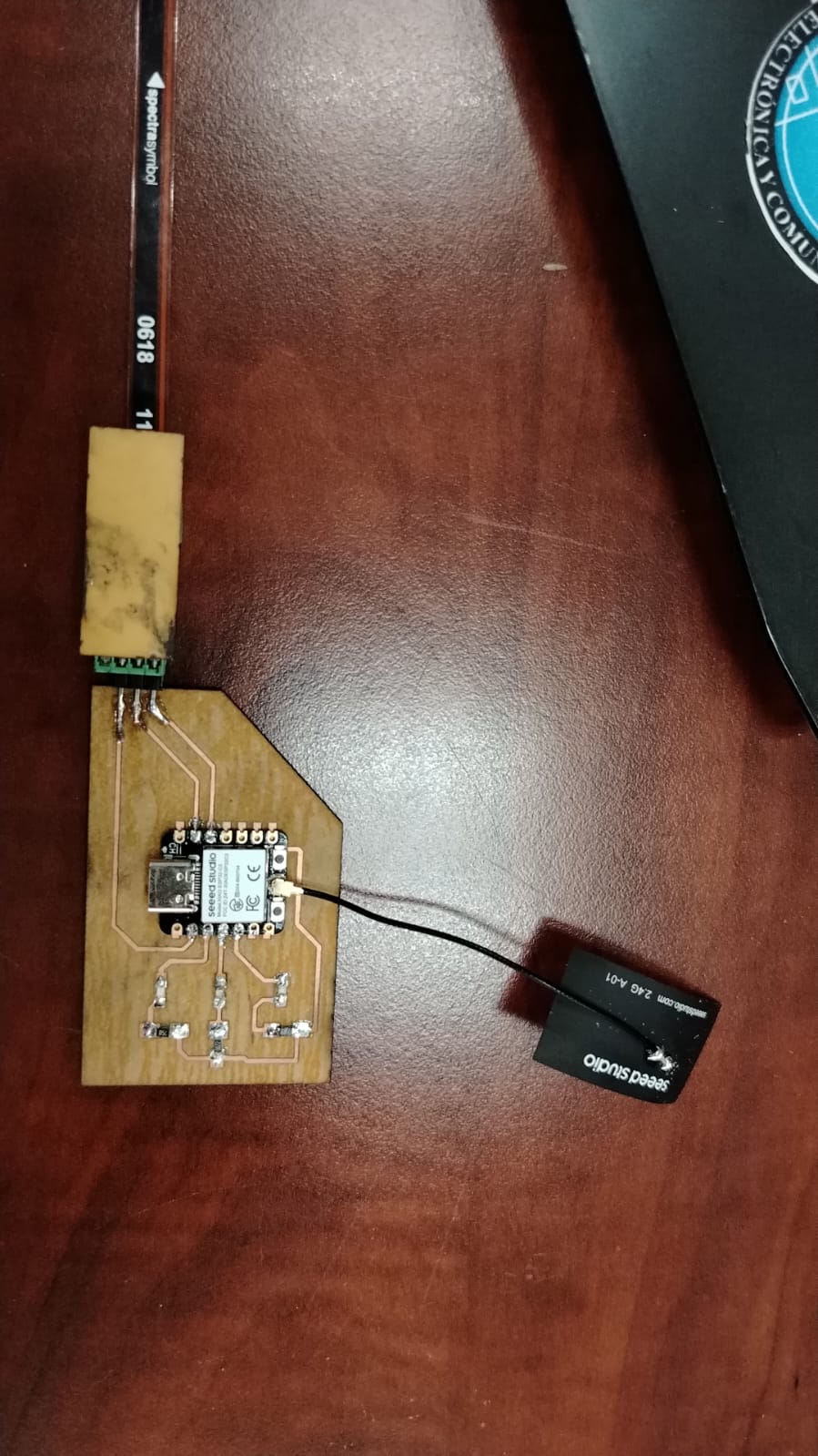
Board 1: Flex Sensor (input device)
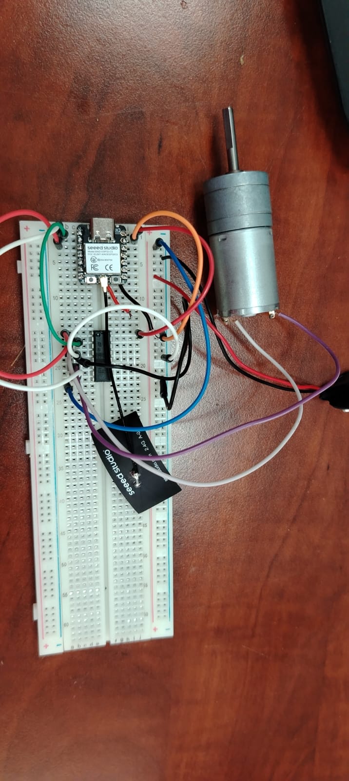
Board 2: DC Motor (output device)
For simplicity, the board with the flex sensor will be referred to as Board 1, and the board with the connected DC motor will be referred to as Board 2.
As shown in the image, the XIAO ESP32-C3 boards include an FPC (sticker-type) antenna that connects to a UFL connector. This allows wireless communication via Bluetooth or WiFi between two XIAO ESP32-C3 boards.
Board 2, which has the DC motor connected, is assembled on a breadboard. Since I ran out of copper boards to manufacture another PCB, and the new ones I ordered have not yet arrived, I had to build the connections for Board 2 using a breadboard.
The components used to assemble the circuit for Board 2 are:
XIAO ESP32C3 microcontroller board
L293D driver to control motor speed and rotation direction
-
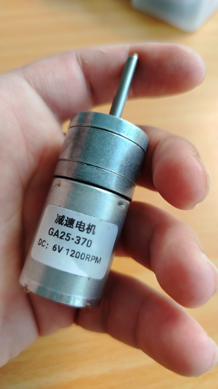
GA25-370 DC motor (6V, 1200 rpm)
- breadboard
- jumper wires
Once the circuit is connected and both boards are working correctly, as shown in Week 10 and Week 09, we can begin programming to establish communication between both boards.
The main idea is to enable communication between both boards: Board 1 (with the flex sensor) and Board 2 (with the DC motor). Data will be sent from Board 1 to Board 2, and the motor will execute an action based on the readings from the flex sensor. For this purpose, I used a communication protocol known as WiFi.
WiFi Connections
To communicate two boards such as the XIAO ESP32-C3 via WiFi, one board must act as a server and the other as a client. The client sends requests, and the server responds. In this case, Board 2 (with the motor) acts as the server, and Board 1 acts as the client. The operation is straightforward: both boards are connected, and one triggers an action based on the other. Specifically, Board 1 (with the flex sensor) sends data to Board 2 (with the DC motor). As the flex sensor bends and the board reads this change, the data is transmitted via WiFi to Board 2, where the motor responds accordingly based on the received information.
Below is the explanation of the code for Board 1, which has the flex sensor connected. This board is responsible for sending information to Board 2.
Programming Board 1 Client Sensor Flex:
First, we declare some libraries that we will use. The <WiFi.h> library allows us to connect to a WiFi network using its built-in functions. The <HTTPClient.h> library allows us to send HTTP requests using the functions it provides.
We also define global variables such as const char* WIFI_SSID = "CIDETE_VERAGUAS"; and const char* WIFI_PASSWORD = "cidetecruvj7n";, which store the WiFi credentials.
Additionally, we declare the variable const char* SERVER_IP = "10.20.6.48";, which stores the IP address of Board 2 (the one with the motor connected).
Finally, we declare const int flexPin = A1;, which is responsible for storing the value read by the XIAO ESP32C3 from the flex sensor.
#include <Arduino.h>
#include <WiFi.h>
#include <HTTPClient.h>

const char* WIFI_SSID = "CIDETE_VERAGUAS";
const char* WIFI_PASSWORD = "cidetecruvj7n";

// Replace this with the IP address printed by Board A.
const char* SERVER_IP = "10.20.6.48";

const int flexPin = A1;

/* ESP32C3 CLIENT - FLEX SENSOR */
// Calibration - adjust these values
int valorRecto = 1800;    // Straight sensor (0°)
int valorDoblado = 2500;  // Bent sensor (90°)
In the following code block, we analyze the void setup() function.
In this section, we initialize serial communication and establish a connection to our local WiFi network.
The system checks every 500 milliseconds whether the connection has been successfully established.
The connection process is performed using the following instructions:
    WiFi.begin(ssid, password);
    while (WiFi.status() != WL_CONNECTED) {
        delay(500);
        Serial.print(".");
    }
As long as the board is not connected, this loop will continue executing until a successful connection is achieved.
void setup() {
  Serial.begin(115200);
  delay(1000);
  analogReadResolution(12);
  analogSetAttenuation(ADC_11db);

  Serial.println("Iniciando...");

  //conectando al WIFI_LOCAL
  WiFi.begin(WIFI_SSID, WIFI_PASSWORD);
  Serial.print("Connecting to Wi-Fi");

  while (WiFi.status() != WL_CONNECTED) {
    delay(500);
    Serial.print(".");
  }

  Serial.println();
  Serial.println("Board B connected to Wi-Fi");
  Serial.print("Board B IP address: ");
  Serial.println(WiFi.localIP());//Imprime direccion ip de la placa

}
Inside the void loop() function, we continuously read the values from the flex sensor using the following line:
int valorADC = analogRead(flexPin);.
Then, we convert this value into an angle using:
float angulo = map(valorADC, valorRecto, valorDoblado, 0, 90);.
This function takes five parameters:
the raw sensor value (valorADC), the calibrated minimum value (valorRecto),
the calibrated maximum value (valorDoblado), and the new desired range (from 0 to 90 degrees).
To ensure the angle remains within valid limits, we use:
angulo = constrain(angulo, 0, 90);,
which prevents values below 0 or above 90 degrees.
Next, we verify that the board is still connected to the WiFi network. If the connection is active,
we build a URL using the following instruction:
String url = "http://" + String(SERVER_IP) + "/motor?val=" + String((int)angulo);.
This URL contains the IP address of the server board (Board 2, where the DC motor is connected), followed by the route /motor?val= and the parameter value, which corresponds to the angle obtained from the flex sensor. This value is sent as an integer and will be processed by the server.
Finally, we initialize and send the HTTP request using:
http.begin(url); and int code = http.GET();.
If the request is successful, the server responds with status code 200, indicating that everything is working correctly.
void loop() {
  int valorADC = analogRead(flexPin);

  // Convert to angle
  float angulo = map(valorADC, valorRecto, valorDoblado, 0, 90);
  angulo = constrain(angulo, 0, 90);

  if(WiFi.status() == WL_CONNECTED){ // check WiFi connection
    HTTPClient http;
    String url = "http://" + String(SERVER_IP) + "/motor?val=" + String((int)angulo);
    Serial.println("Sending: " + url);
    http.begin(url);
    int code = http.GET();
    Serial.println("Response: " + String(code));
    http.end();
  }

  delay(50);
}
Programming the Server Board for DC Motor Control
The following code corresponds to Board 2, which acts as the server and controls the DC motor based on the data received from Board 1.
First, we include the required libraries: <WiFi.h> to establish the WiFi connection and <WebServer.h> to create a local web server on the ESP32C3.
We then define the WiFi credentials using the variables ssid and password, which allow the board to connect to the same network as the client.
The line WebServer server(80); creates a web server that listens on port 80, which is the default port for HTTP communication.
Next, we define the motor control pins:
EN is used to control the motor speed using PWM,
while IN1 and IN2 control the rotation direction of the motor.
#include <WiFi.h>
#include <WebServer.h>

const char* ssid     = "CIDETE_VERAGUAS";
const char* password = "cidetecruvj7n";

WebServer server(80);

const int EN  = D2;  // Enable (PWM speed)
const int IN1 = D1;  // Direction 1
const int IN2 = D0;  // Direction 2
The function handleMotor() is executed when the server receives a request at the route /motor.
It checks if the request contains a parameter named val, which represents the angle sent from Board 1.
If the parameter exists, it is converted into an integer value using toInt().
Then, a condition is applied:
if the value is less than 75, the motor rotates forward; otherwise, the motor stops.
The motor control is achieved by setting the states of IN1 and IN2,
and adjusting the speed using analogWrite(EN, value).
Finally, the server sends a response with status code 200 and a simple "OK" message to confirm that the request was processed correctly.
void handleMotor() {
  if (server.hasArg("val")) {
    int val = server.arg("val").toInt();

    if (val < 75) {
      // Flex bent → motor forward
      digitalWrite(IN1, HIGH);
      digitalWrite(IN2, LOW);
      analogWrite(EN, 200);
    } else {
      // Stop motor
      digitalWrite(IN1, LOW);
      digitalWrite(IN2, LOW);
      analogWrite(EN, 0);
    }

    server.send(200, "text/plain", "OK");
  }
}
In the setup() function, we initialize serial communication and configure the motor control pins as outputs.
Then, the board connects to the WiFi network using the provided credentials.
Once connected, the board prints its local IP address to the serial monitor. This IP address is important because it will be used by the client (Board 1) to send HTTP requests.
The line server.on("/motor", HTTP_GET, handleMotor); defines the route that will trigger the handleMotor() function.
Finally, server.begin(); starts the web server.
void setup() {
  Serial.begin(115200);
  pinMode(EN,  OUTPUT);
  pinMode(IN1, OUTPUT);
  pinMode(IN2, OUTPUT);

  WiFi.begin(ssid, password);
  while (WiFi.status() != WL_CONNECTED) {
    delay(500);
    Serial.print(".");
  }
  Serial.println("IP: " + WiFi.localIP().toString());

  server.on("/motor", HTTP_GET, handleMotor);
  server.begin();
}
In the loop() function, the server continuously listens for incoming client requests.
This is done using server.handleClient();, which ensures that any request sent by Board 1 is processed in real time.
void loop() {
  server.handleClient();
}
In summary, this board acts as a server that receives data from the client (Board 1) via WiFi and controls the DC motor accordingly based on the received angle value.
una vez tengo ya la programacion he cargado el codigo a las placas para alimentar las placa1 y placa2 he usado los puertos USB de mi laptop
result de conexion de dos placas XIAO ESP32-C3 mediante WiFi
As shown, every time the flex sensor is bent, an action is triggered on Board 2, which starts the motor moving forward. When the flex sensor on Board 1 is released, the motor stops. This demonstrates a simple interaction: Board 1 (Node 1 – client) sends a request, and Board 2 (Node 2 – server) executes the corresponding action. Both boards must be connected to the same WiFi network for this system to work correctly.
ESP-NOW Connection
Next, I will test the ESP-NOW connection. This communication protocol is specifically designed for ESP32 boards developed by Espressif. It allows two or more ESP32 devices to communicate directly using their MAC addresses.
Although the <WiFi.h> library is used, ESP-NOW does not require WiFi credentials or connection to a local network.
Instead, communication is established directly between devices, making it faster, with lower latency and reduced power consumption compared to standard WiFi communication.
In this setup, we define two nodes: a transmitter and a receiver. The board connected to the flex sensor will act as the data transmitter, while the board connected to the DC motor will act as the data receiver.
The receiver board executes actions (such as starting the motor) based on the data sent by the transmitter board. In the following section, I will explain the code for the data transmitter.
The following code corresponds to the ESP-NOW transmitter (Board 1), which reads data from the flex sensor and sends it wirelessly to the receiver board (Board 2) using the ESP-NOW protocol.
First, we include the required libraries: <WiFi.h> and <esp_now.h>.
The WiFi library is required to configure the ESP32 in station mode, while the ESP-NOW library enables direct communication between ESP32 devices.
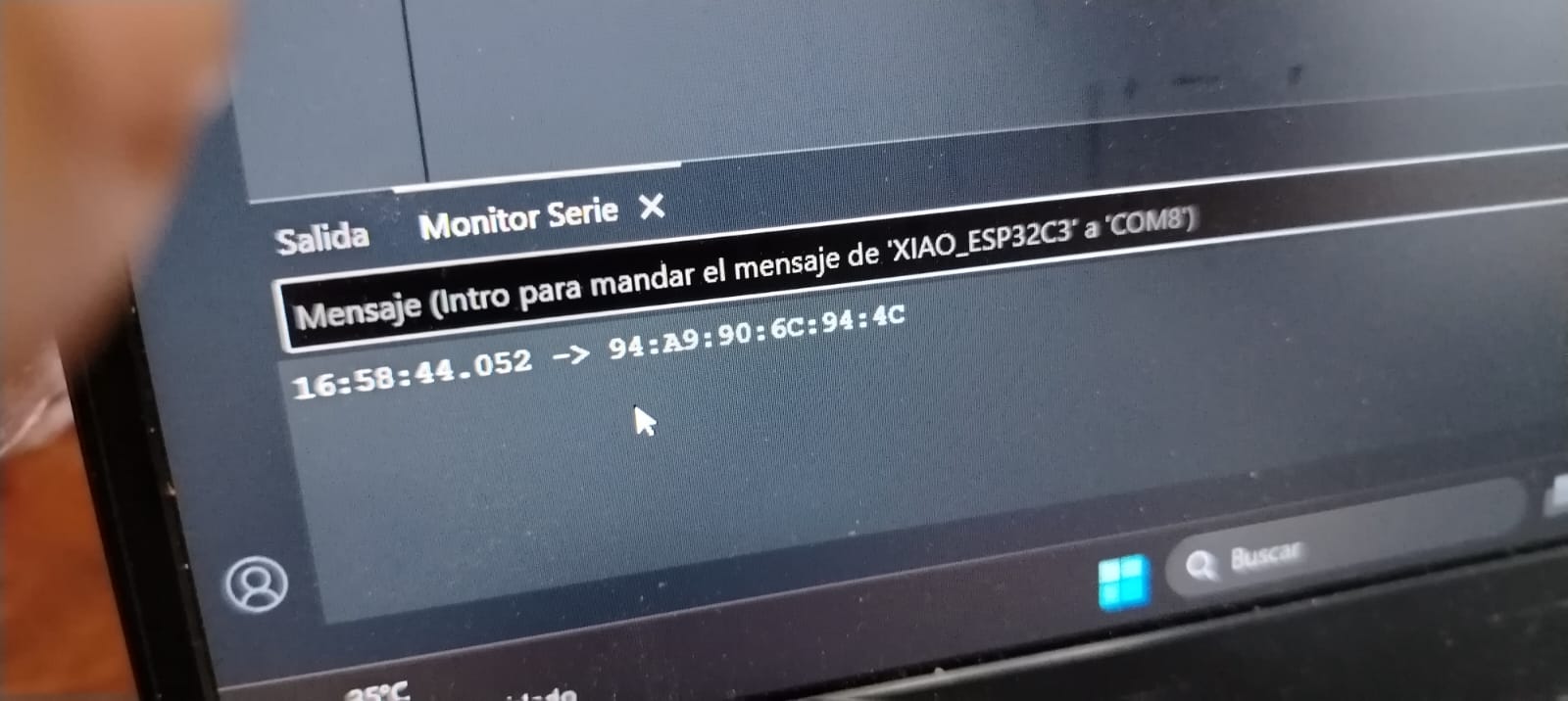
The variable macServidor stores the MAC address of the receiver board.
This address is essential because ESP-NOW uses MAC addresses instead of IP addresses to identify devices.
To obtain the MAC address of the receiver board, I used the following code and uploaded it to the receiver device.
#include <WiFi.h>

void setup() {
  Serial.begin(115200);
  WiFi.mode(WIFI_STA);
  Serial.println(WiFi.macAddress());
}

void loop() {}
This code prints the MAC address of the board in the serial monitor. The obtained MAC address is then used in the transmitter program to establish communication using the ESP-NOW protocol.
Next, we define the flex sensor pin FLEX_PIN and calibration values valorRecto and valorDoblado,
which represent the sensor readings when it is straight and fully bent.
We then define a structure using typedef struct, called Mensaje.
This structure allows us to package the data (in this case, the angle value) into a format that can be sent using ESP-NOW.
#include <WiFi.h>
#include <esp_now.h>

// MAC address of the receiver (server)
uint8_t macServidor[] = {0x94, 0xA9, 0x90, 0x6C, 0x94, 0x4C};

const int FLEX_PIN = A1;
int valorRecto   = 1800;
int valorDoblado = 2500;

typedef struct {
  int valor;
} Mensaje;

Mensaje dato;
esp_now_peer_info_t peer;
In the setup() function, we initialize serial communication and configure the ADC resolution for more precise readings.
The function analogReadResolution(12) sets a 12-bit resolution, and analogSetAttenuation(ADC_11db) adjusts the input range.
Then, the ESP32 is configured in station mode using WiFi.mode(WIFI_STA);, which is required for ESP-NOW.
After that, esp_now_init(); initializes the ESP-NOW protocol.
The receiver board is registered as a peer using its MAC address.
This is done by copying the address into the peer structure and adding it with esp_now_add_peer(&peer);.
void setup() {
  Serial.begin(115200);
  analogReadResolution(12);
  analogSetAttenuation(ADC_11db);

  WiFi.mode(WIFI_STA);
  esp_now_init();

  // Register receiver as peer
  memcpy(peer.peer_addr, macServidor, 6);
  peer.channel = 0;
  peer.encrypt = false;
  esp_now_add_peer(&peer);
}
In the loop() function, the system continuously reads the analog value from the flex sensor using analogRead(FLEX_PIN);.
This value is then converted into an angle using the map() function and constrained between 0 and 90 degrees using constrain().
The measured values are printed to the serial monitor for debugging purposes.
Then, the angle is assigned to the structure dato.valor, which will be sent to the receiver.
Finally, the data is transmitted using esp_now_send(), which sends the structure to the specified MAC address.
This process repeats continuously with a short delay of 40 milliseconds.
void loop() {
  int valorADC = analogRead(FLEX_PIN);
  int angulo = map(valorADC, valorRecto, valorDoblado, 0, 90);
  angulo = constrain(angulo, 0, 90);

  Serial.print("ADC: ");
  Serial.print(valorADC);
  Serial.print(" | Angle: ");
  Serial.println(angulo);

  dato.valor = angulo;
  esp_now_send(macServidor, (uint8_t*)&dato, sizeof(dato));

  delay(40);
}
In summary, this board acts as a transmitter that reads the flex sensor, converts the data into an angle, and sends it directly to the receiver board using ESP-NOW, enabling fast and efficient wireless communication without the need for a WiFi network.
Next, we will program the receiver board, which executes an action based on the values received from the transmitter board. In this case, it controls the DC motor according to the incoming data.
The following code corresponds to the ESP-NOW receiver (Board 2), which receives data from the transmitter board (Board 1) and controls the DC motor based on the received values.
First, we include the required libraries: <WiFi.h> and <esp_now.h>.
These libraries allow the ESP32 to operate in station mode and enable ESP-NOW communication.
Next, we define the motor control pins:
EN is used for PWM speed control,
while IN1 and IN2 determine the direction of the motor.
We define a structure called Mensaje, which is used to receive the data sent by the transmitter.
This structure must match exactly the one defined in the sender code.
#include <WiFi.h>
#include <esp_now.h>

const int EN  = D2;
const int IN1 = D1;
const int IN2 = D0;

// Data structure to receive
typedef struct {
  int valor;
} Mensaje;

Mensaje dato;
The function onDataRecv() is a callback function that is automatically executed whenever data is received via ESP-NOW.
Inside this function, we use memcpy() to copy the incoming data into the dato structure.
Then, we print the received value to the serial monitor for debugging purposes.
A condition is applied based on the received value: if the value is less than 75, the motor rotates forward; otherwise, the motor stops.
The motor is controlled by setting the states of IN1 and IN2,
and adjusting the speed using analogWrite(EN, value).
// Executed when data is received
void onDataRecv(const esp_now_recv_info* info, const uint8_t* data, int len) {
  memcpy(&dato, data, sizeof(dato));
  Serial.print("Received value: ");
  Serial.println(dato.valor);

  if (dato.valor < 75) {
    digitalWrite(IN1, HIGH);
    digitalWrite(IN2, LOW);
    analogWrite(EN, 200);
  } else {
    digitalWrite(IN1, LOW);
    digitalWrite(IN2, LOW);
    analogWrite(EN, 0);
  }
}
In the setup() function, we initialize serial communication and configure the motor control pins as outputs.
Then, the ESP32 is set to station mode using WiFi.mode(WIFI_STA);, which is required for ESP-NOW operation.
The protocol is initialized with esp_now_init();.
The line esp_now_register_recv_cb(onDataRecv); registers the callback function,
meaning that every time data is received, the onDataRecv() function will be executed automatically.
void setup() {
  Serial.begin(115200);
  pinMode(EN,  OUTPUT);
  pinMode(IN1, OUTPUT);
  pinMode(IN2, OUTPUT);

  WiFi.mode(WIFI_STA);
  esp_now_init();
  esp_now_register_recv_cb(onDataRecv);
}
The loop() function is empty because all the logic is handled through the callback function.
The system reacts automatically whenever new data is received.
void loop() {}
In summary, this board acts as a receiver that listens for incoming ESP-NOW messages, processes the received data, and controls the DC motor in real time based on the transmitted angle value.
Below, we can observe in the serial monitor how the receiver board gets the values from the transmitter board.
Below, we can observe the results using the ESP-NOW connection protocol.
What I Learned
This week I learned how to communicate two XIAO ESP32-C3 boards with each other, allowing one to execute actions based on the other. I also learned how to connect both boards using WiFi and the ESP-NOW protocol. Both use the 2.4 GHz communication frequency. Additionally, I learned that the ESP-NOW protocol is faster, has lower latency compared to WiFi connection, and consumes less power. I also learned that ESP-NOW is only available for ESP32 chips. Personally, I preferred ESP-NOW because its programming is easier to understand.
Dowload File
Mission accomplished! 😊