Group assignment
Objective
-
Measure the power consumption of an output device. Document your work on the group work page and reflect on your individual page what you learned.
Here I share the link to my group assignment.
Indivual assignment
- Add an output device to a microcontroller board you’ve designed and program it to do something.
What I know
This week's assignment is to add an output device to a board that we had already designed. However, I decided to create a new board to control an output device, since last week (Week 9) I added an input device, which was a flex sensor. For this week, I will design a new PCB to connect and control a DC motor, as it is an output device that I may use in my final project.
For this purpose, I designed the circuit using KiCad.
The components I will use are:
XIAO ESP32C3 microcontroller board
L293D driver to control the motor speed and rotation direction
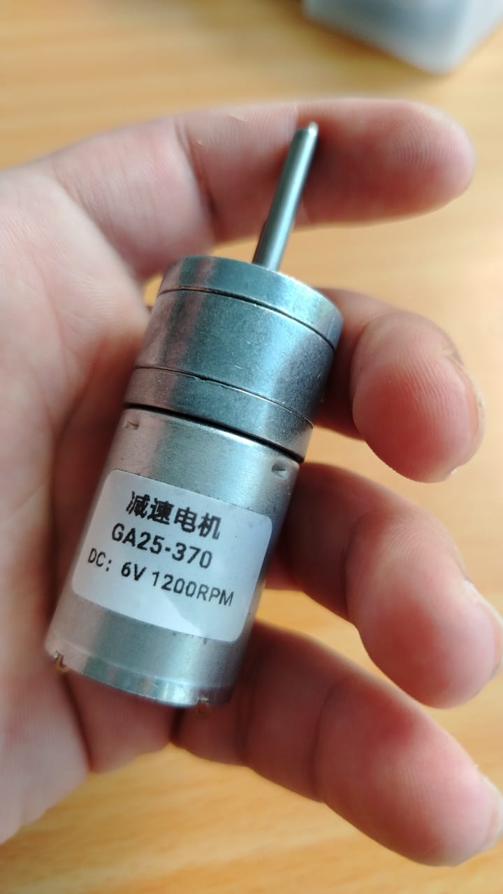
GA25-370 DC motor (6V, 1200 rpm)
78M05 voltage regulator (5V output)
3 electrolytic capacitors (100uF), which are the ones I currently have available
SS14 diode for protection when connecting the battery to the XIAO ESP32C3
Switch to control power on/off
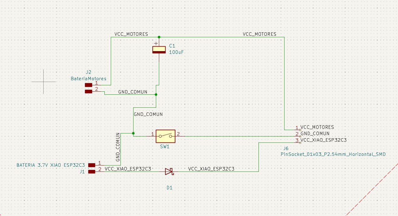
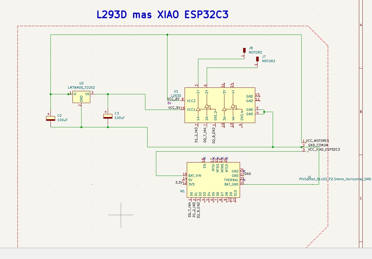
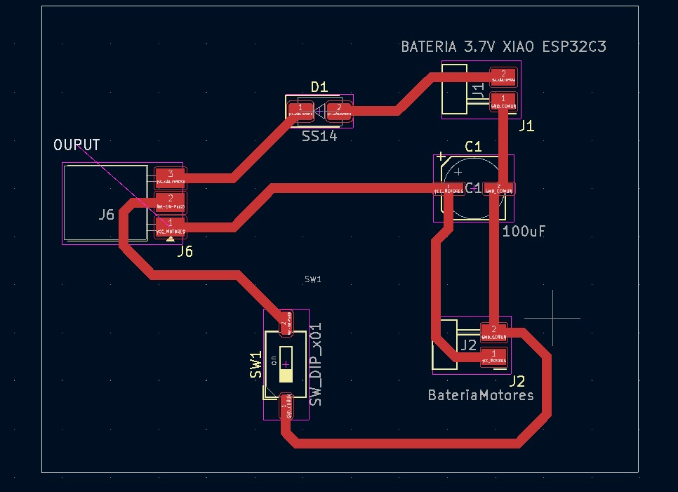
Below, I show the general schematic of my PCB:
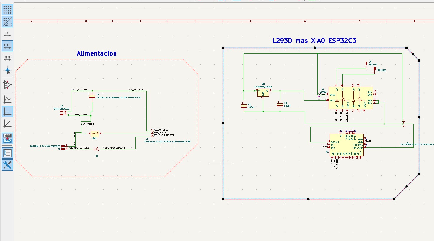
As shown in the image, I have two schematics: one for powering the board and the motors, and another where the L293D driver and the XIAO ESP32C3 are connected. A linear 78M05 regulator is used, which supports an input range from 5V to 36V and provides a regulated 5V output. Additionally, I am powering the motor with 6V using a variable power supply, since the motor is rated at 6V.
Below, I show the PCB routing:
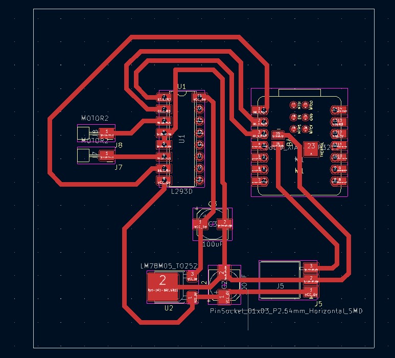
With this design, I can proceed to manufacture the PCB as I learned in Week 7.
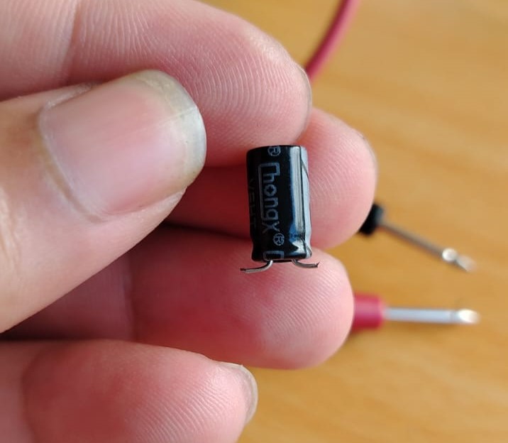
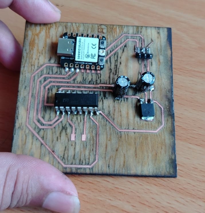
I started soldering the components. Since I do not have all the required components, I made some adaptations, such as with the switch and capacitors. For example, I trimmed the capacitor leads as shown in the image below and then soldered them onto the PCB.
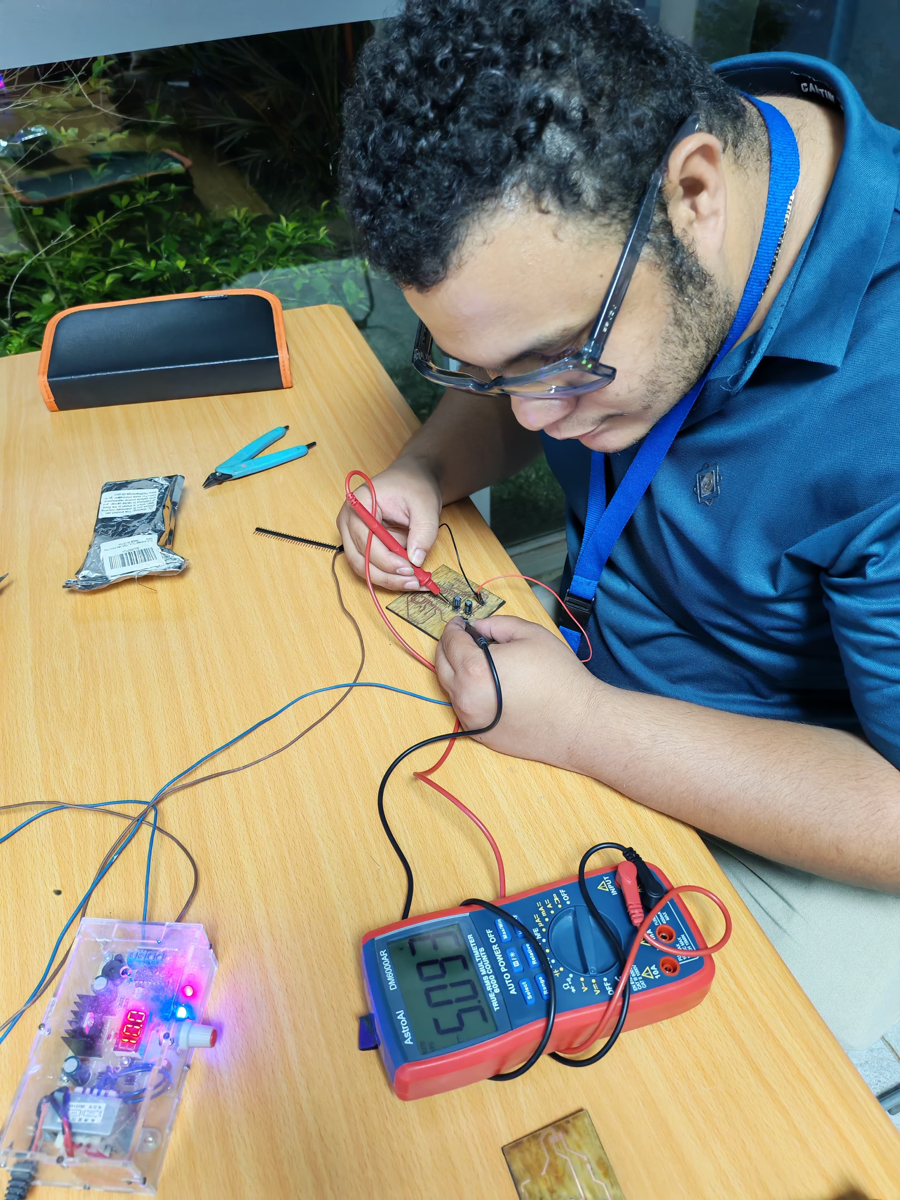
The first components I soldered onto the board were the capacitors and the 78M05 voltage regulator. After that, I tested it by applying voltage to verify its functionality. As shown in the image below, it successfully regulated the voltage from 10V down to approximately 5V.
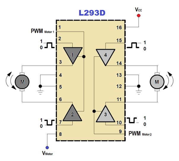
In the image, we can see that the input voltage is 10V and the output is 5V. This output will be connected to pin 16 of the L293D motor driver, while the 10V will be used to power the motor. Up to this point, everything is working as expected. Next, I soldered the remaining components such as the L293D and the XIAO ESP32C3 board. In the following link, you can find the pin configuration and an explanation of how the driver works: L293D reference. Additionally, here is another resource explaining the connections: L293D explanation.
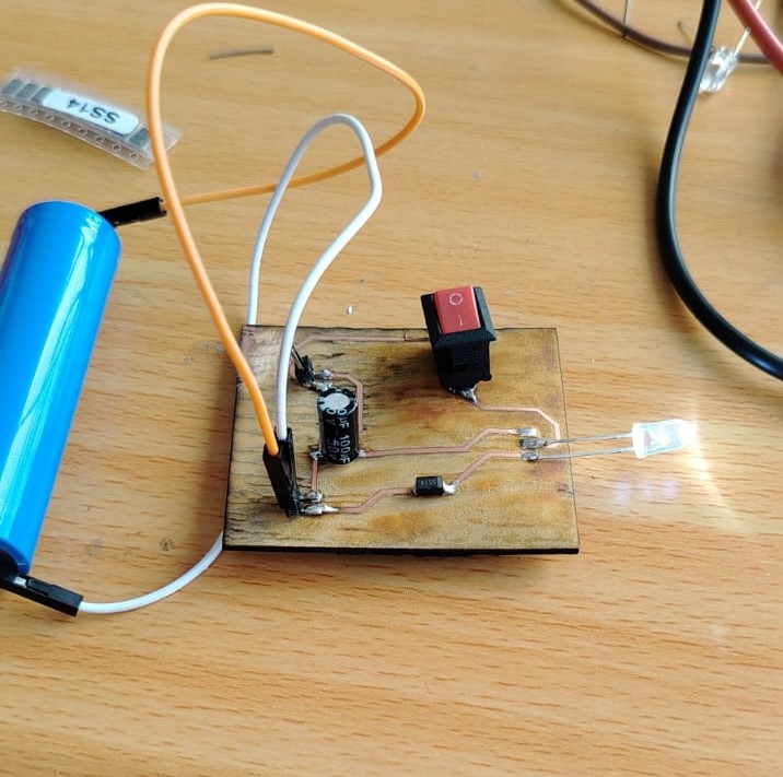
After that, I assembled the power supply board where the batteries will be connected. One battery powers the XIAO ESP32C3, while the other supplies power to the L293D driver. This board includes a switch, an SS14 diode, and a 100uF capacitor for the motor supply. The SS14 diode provides protection to the XIAO ESP32C3 in case the 3.7V battery is connected with reversed polarity.
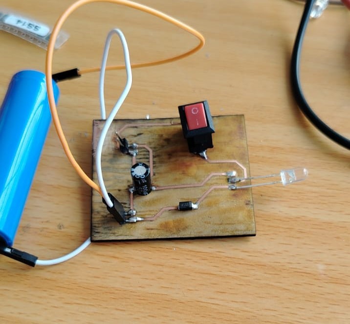
To verify that everything was working correctly, I connected an LED to the output and reversed the battery polarity. As shown below, the protection circuit worked correctly.
Correct polarity
Reversed polarity
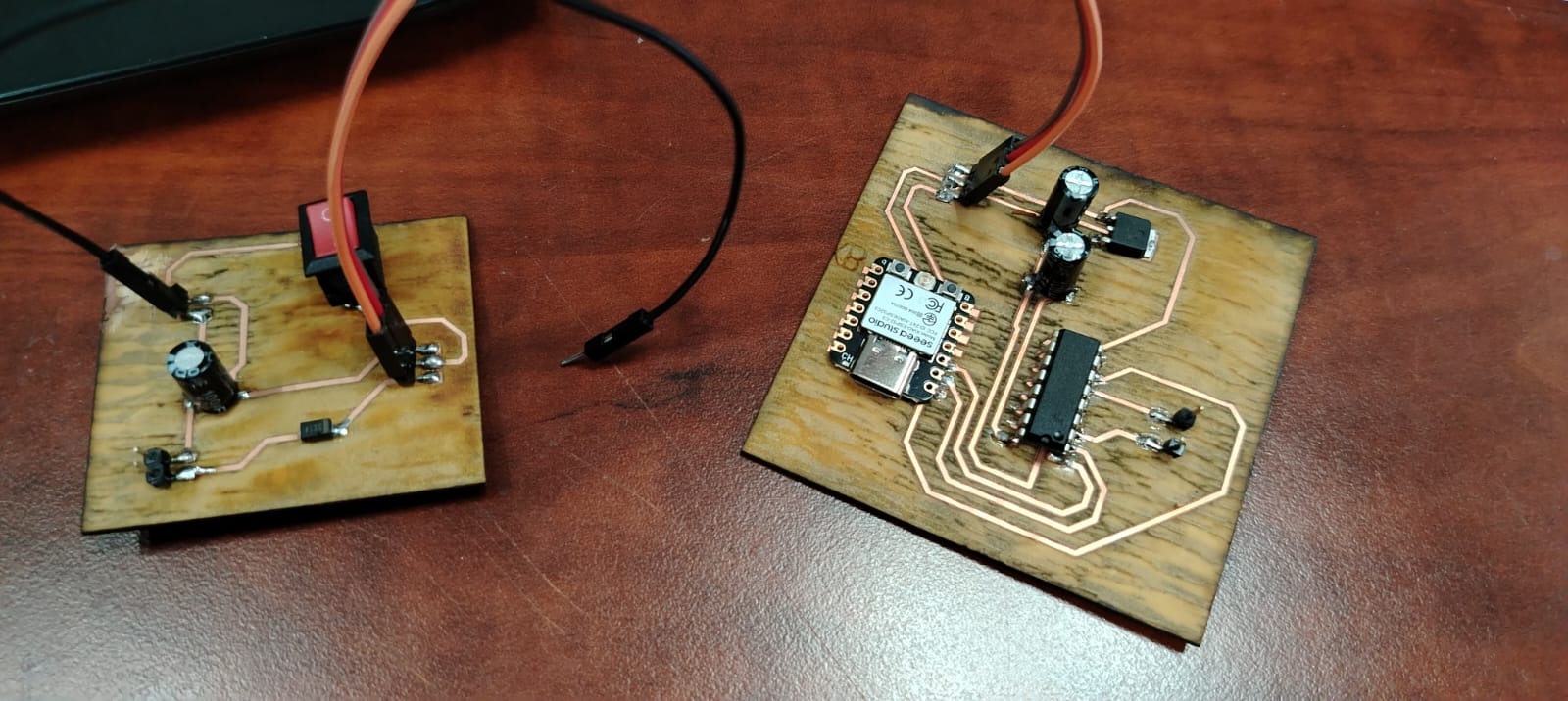
Once everything was connected, the final assembly looked like this:
At this stage, I proceeded with the programming to control the motor.
                                // Conexiones del driver L293D para un motor DC
                                    int enA = D2;
                                    int in1 = D1;
                                    int in2 = D0;

                                    void setup() {
                                    // Colocando los pines en modo salida
                                    pinMode(enA, OUTPUT);
                                    pinMode(in1, OUTPUT);
                                    pinMode(in2, OUTPUT);
                                    }

                                    void loop() {
                                    // Iniciamos con el motor detenido
                                    digitalWrite(in1, LOW);
                                    digitalWrite(in2, LOW);
                                    delay(2000);

                                    // Máxima velocidad del motor
                                    analogWrite(enA, 255);

                                    // Encendemos el motor
                                    digitalWrite(in1, HIGH);
                                    digitalWrite(in2, LOW);
                                    delay(2000);

                                    // Invertimos el sentido del giro del motor
                                    digitalWrite(in1, LOW);
                                    digitalWrite(in2, HIGH);
                                    delay(2000);

                                    // Apagamos el motor
                                    digitalWrite(in1, LOW);
                                    digitalWrite(in2, LOW);
                                    delay(2000);

                                    // Turn on motors
                                    digitalWrite(in1, HIGH);
                                    digitalWrite(in2, LOW);

                                    // Aumenta la velocidad de cero a máximo
                                    for (int i = 0; i < 256; i=i+1) {
                                        analogWrite(enA, i);
                                        delay(50);
                                    }

                                    // Disminuye la velocidad de máximo a cero
                                    for (int i = 255; i >= 0; i=i-1) {
                                        analogWrite(enA, i);
                                        delay(50);
                                    }

                                    }
After uploading the code to my XIAO ESP32-C3 board and running the program, it did not work, and this is where I encountered a major issue.
The system was not responding at all; it was as if it was not powered on. Additionally, the power cables started to heat up, so I immediately disconnected them.
I checked my XIAO ESP32-C3 board to ensure it was not damaged, and fortunately, it was working properly.
I also verified the L293D driver, and it was in good condition.
Then, I checked the voltage output from the regulator, and it was providing the expected values.
However, I noticed that when I measured the output voltage at pins 3 and 6 (the motor outputs of the driver), there was no voltage present.
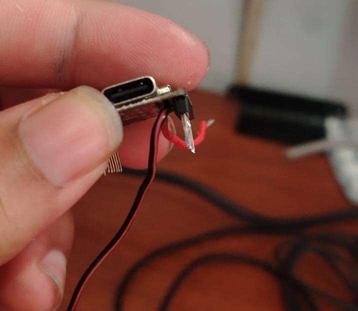
To make sure the power pads had proper contact, I soldered vertical headers to the XIAO ESP32-C3 and connected jumper wires, as shown below:
This is the pin diagram of the L293D:
These are my PCB connections:
Honestly, I spent three days trying to figure out the problem without success. My conclusion is that I am not powering the circuit correctly, which is affecting its operation.
Since I ran out of time, I decided to rebuild the circuit on a breadboard. I also ran out of available PCB material, so I will need to order more.
I recreated the same connections on the breadboard. This time, I powered the XIAO ESP32-C3 via USB and used a 9V battery only for the motor supply. I also powered the logic side of the L293D driver with 5V provided by the XIAO ESP32-C3. After uploading the same code as before, the motor started working as expected.
Personally, I am not fully satisfied with the results, since I was not able to get my PCB working as intended. However, I was able to successfully test the output device (the DC motor) using a breadboard and the XIAO ESP32-C3.
Despite this, the experience taught me many valuable lessons. For my final project, I will take a different approach, especially regarding power management. I plan to power the XIAO ESP32-C3 using a power bank, as it is more practical for my needs.
What I learned about output devices
One of the main things I learned this week about output devices is that they require proper power management and control circuitry in order to function correctly. Unlike input devices, output devices such as DC motors demand higher current and, in most cases, cannot be driven directly by a microcontroller.
I learned that it is essential to use a motor driver, such as the L293D, to safely control the speed and direction of a DC motor. Additionally, output devices often require an independent power supply, since the microcontroller alone cannot provide enough current to operate them.
Another important lesson is that not all motor drivers are compatible with every type of motor. For example, drivers like the A4988 are specifically designed for stepper motors, while in my case, I needed a driver suitable for DC motors GA25-370, such as the L293D, to control my GA25-370 motor.
Finally, I learned that PCB design plays a critical role when working with output devices. Issues such as poor power routing, lack of proper grounding, or inadequate trace width can prevent the system from working correctly, even if the code and components are functioning as expected.
Dowload File
Mission accomplished! 😊