Group assignment
Objective
-
do your lab's safety training
-
test runout, alignment, fixturing, speeds, feeds, materials, and toolpaths for your machine
Here I share the link to my group assignment.
Explaind what you learned
During this process, I learned that CNC routers are very useful machines, but they must be operated with caution. In fact, this was only my second time using this type of equipment, so the experience was very valuable for me.
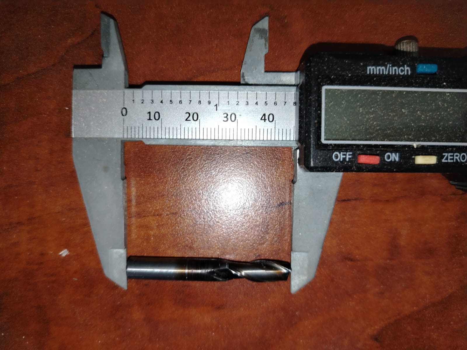
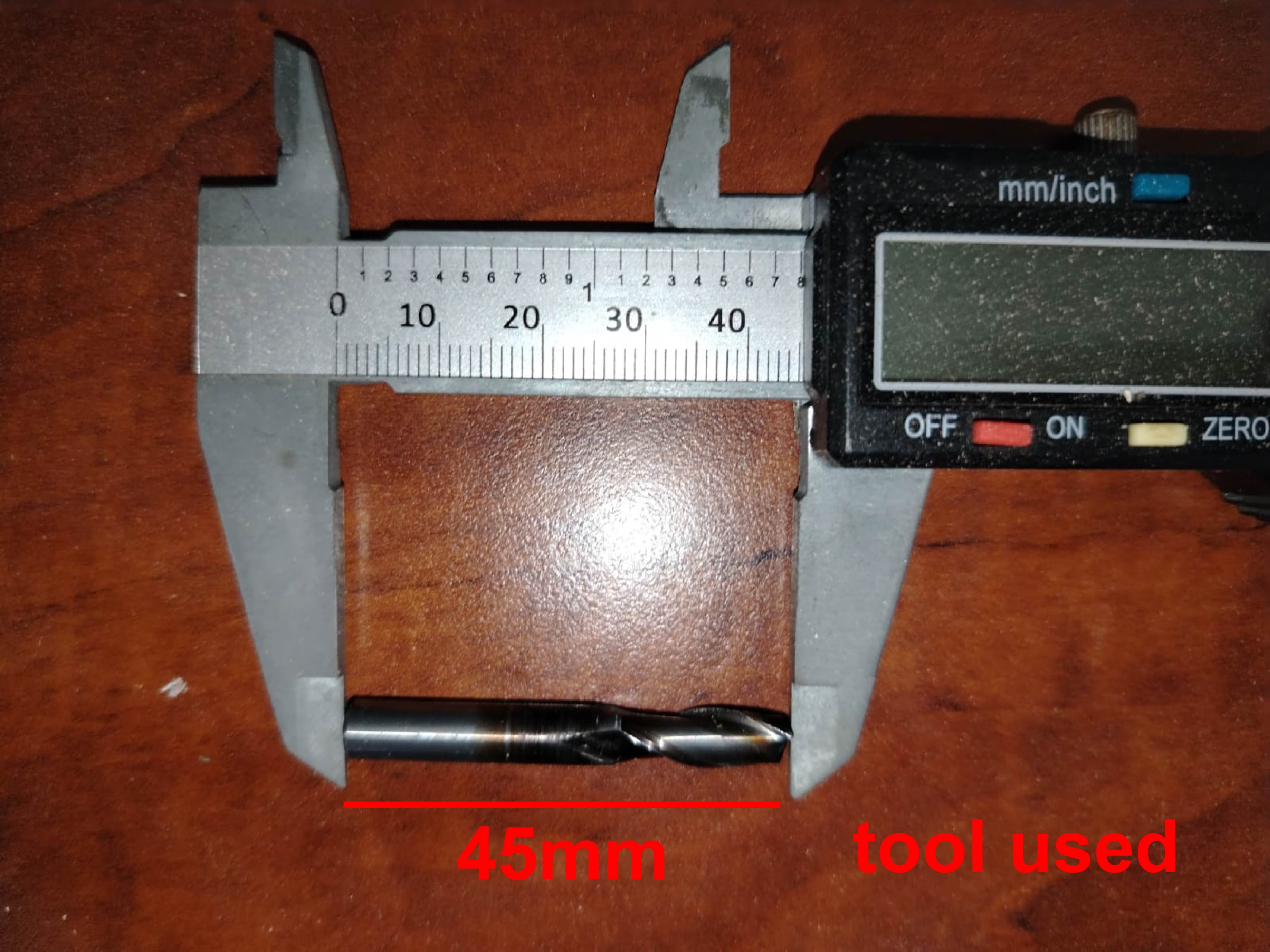
I also learned that knowing the exact diameter of the cutting tool is extremely important. If the tool diameter is configured incorrectly in the CAM software, the final dimensions of the parts may differ from the original design. This could prevent the pieces from fitting together properly during assembly.
Another important concept I learned was the use of dogbones. Dogbones are necessary when designing press-fit joints because the milling tool is round and cannot create perfectly sharp internal corners. By adding dogbones, the parts can fit together correctly during the assembly process.
Indivual assignment
make (design+mill+assemble) something big (~meter-scale)s
To develop my design, I used the software Fusion 360. The object I decided to fabricate is a chair.
As shown in the video below, the first step in designing the chair was creating the legs. At the beginning I only designed two legs, but as the design process progressed I made several modifications and improvements. After modeling part of the legs, I proceeded to draw the ribs that form the seat structure of the chair. In the video it can be seen that I tried several times to draw this component because I was not satisfied with the initial results. After multiple attempts, I finally achieved a design that I liked. Next, I used the extrude tool and then applied a rectangular pattern to replicate the element nine times, which gave the chair its final ribbed structure. At the end of the design process, I made some final adjustments, such as adding a third leg connected to the others in order to increase the structural strength and stability of the chair.
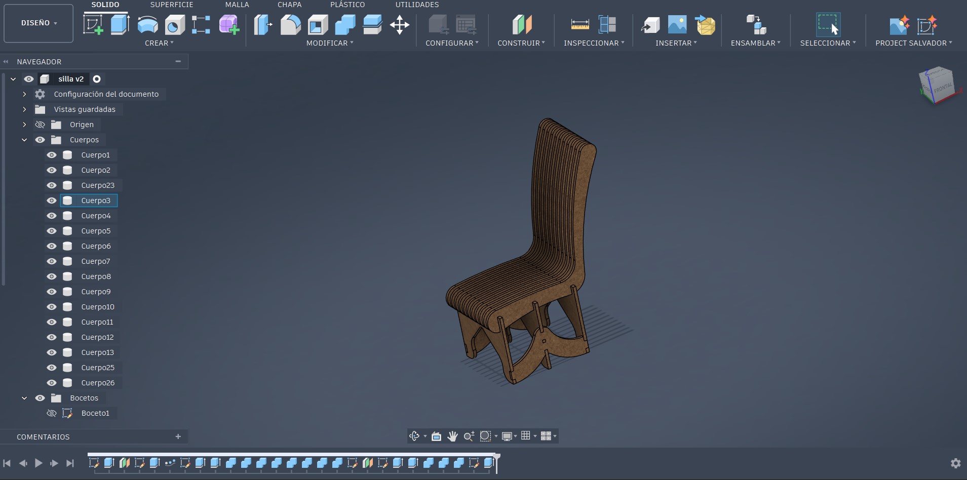
The final design is shown in the image below. At this stage, the last adjustments were made to the model to improve its structural stability, ergonomics, and manufacturability. The design is composed of a series of parallel ribs that form both the seat and the backrest, allowing the load to be distributed evenly. Additionally, lower supports were integrated to function as legs, providing stability and ensuring that the structure remains firm during use.
File Preparation
Once the design was completed, the next step was to generate the 2D drawings from the 3D model. I used the same method that I applied in Week 3, but this time for my chair design. In this case, I only exported the drawings for the legs and two of the ribs that form the seat. Since these ribs are repeated components, I planned to duplicate them later using Adobe Illustrator in order to organize the cutting layout efficiently. After obtaining the required drawings, I exported the 2D design as a PDF file so it could be opened and edited in Adobe Illustrator.
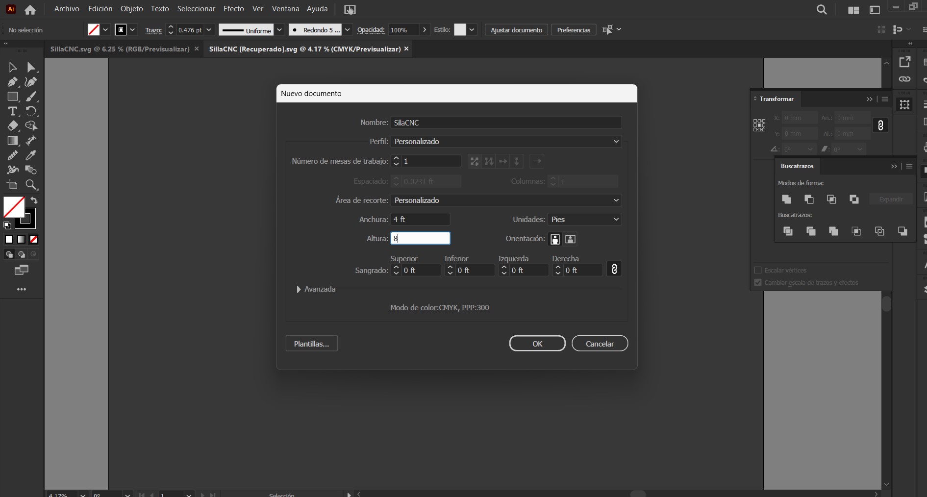
Next, I opened the 2D drawings of my chair in Adobe Illustrator. I created a new project and defined a workspace with dimensions of 4 by 8 feet, which corresponds to the actual size of the material sheet that will be used for fabrication.
Opening the chair drawing file.
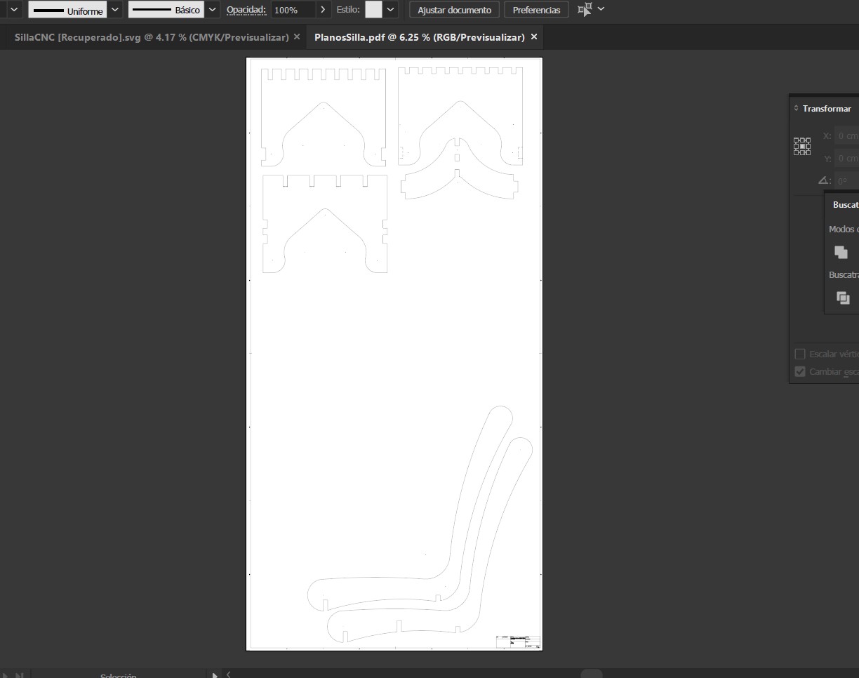
As shown in the image above, we can observe the 2D drawings that compose the chair. Only two ribs of the seat structure are displayed because, as mentioned earlier, these pieces are identical and will be duplicated according to the quantity required. The next step was to create a new workspace in Adobe Illustrator with dimensions of 4 × 8 feet, as shown below.
This step mainly involves organizing the pieces within the working area. The process includes copying, duplicating, and rotating the components while ensuring that all pieces remain within the boundaries of the sheet. It is important to remember that the workspace size represents the real dimensions of the material that will be used during fabrication. After organizing all the parts correctly, the layout should look similar to the arrangement shown in the following image.
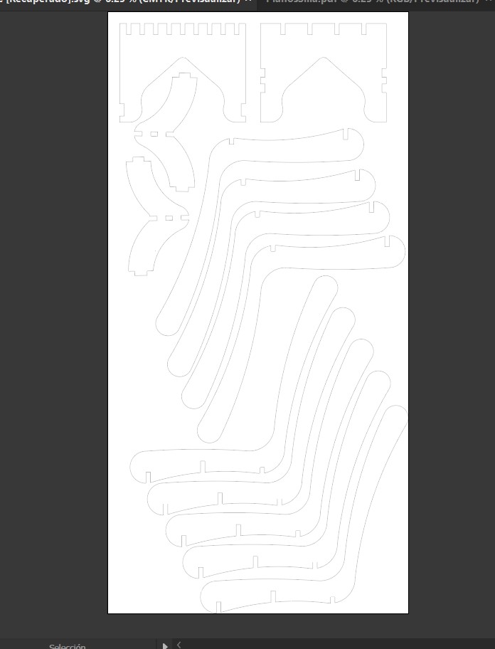
As shown in the image above, one piece is still missing: the rear leg of the chair. This step helped me realize that the available material would not be enough to include all the components on a single sheet. Initially, I thought the chair would require less material, but after arranging the pieces I discovered that I will need to use an additional leftover piece of the same material to fabricate the missing component.
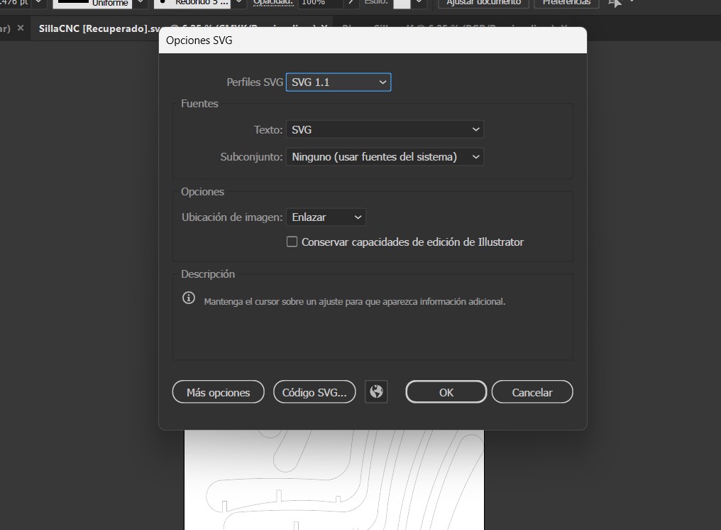
After finishing the layout organization, the file was saved in SVG format.
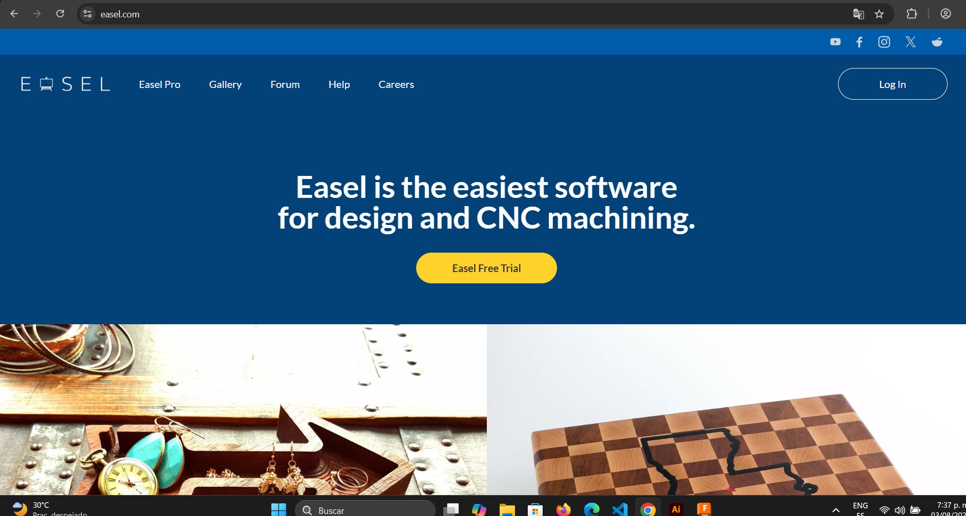
Once this step was completed, the next stage was to use a machining software. In this case, I used Easel, which is a web-based application that allows users to generate toolpaths for CNC machining. Easel supports 2D and 2.5D machining. Since all the parts required for fabricating my chair are 2D cuts, this software works perfectly for this project.
The first step is to access the Easel website. Once there, you can either create a new account or log in if you already have one.
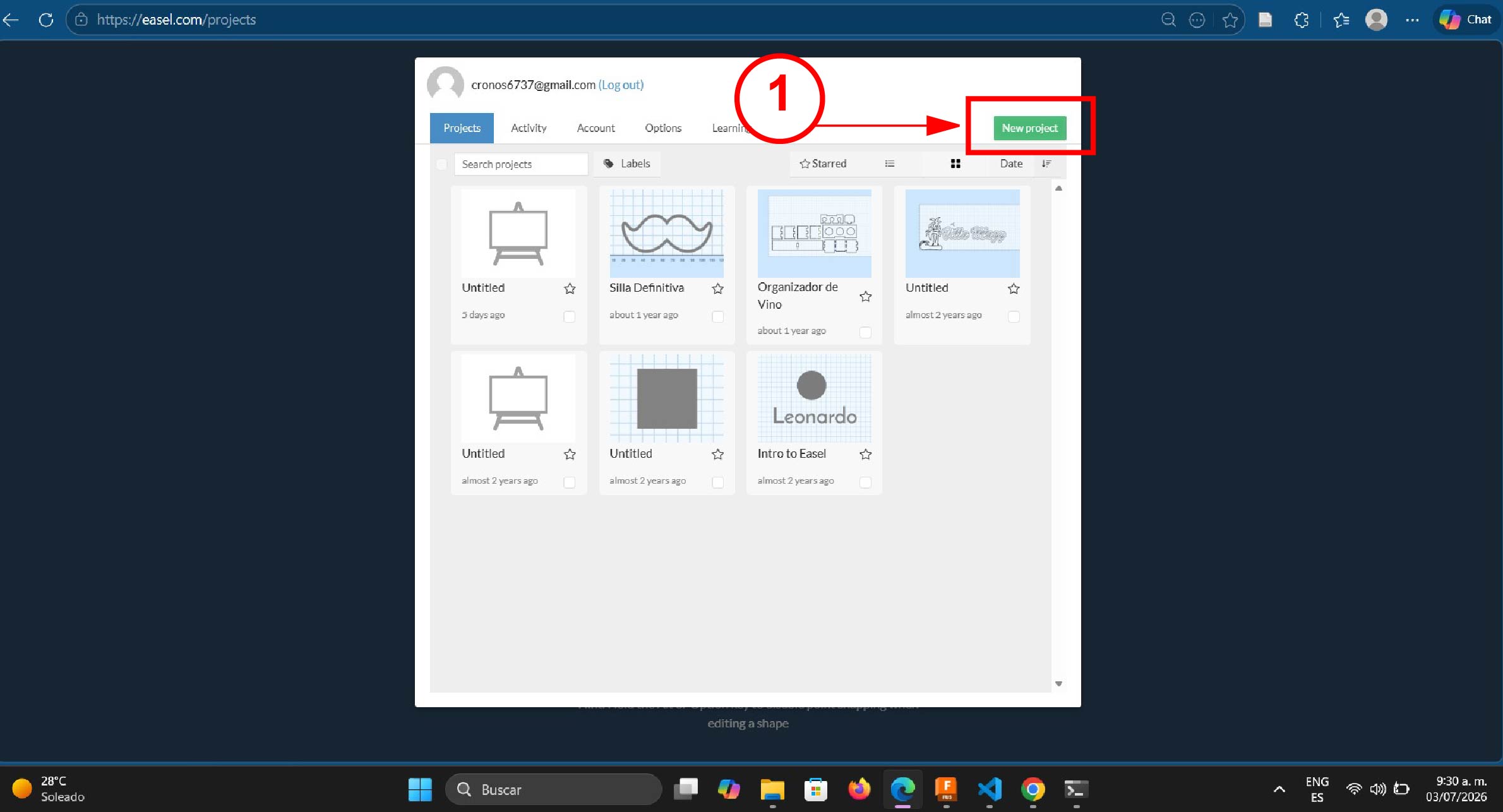
After logging in, a window will appear where you can create a new project.
Once a new project is created, the workspace interface will open. This is where the CNC machining setup will be configured.
Below is a brief description of the main interface elements of this software.
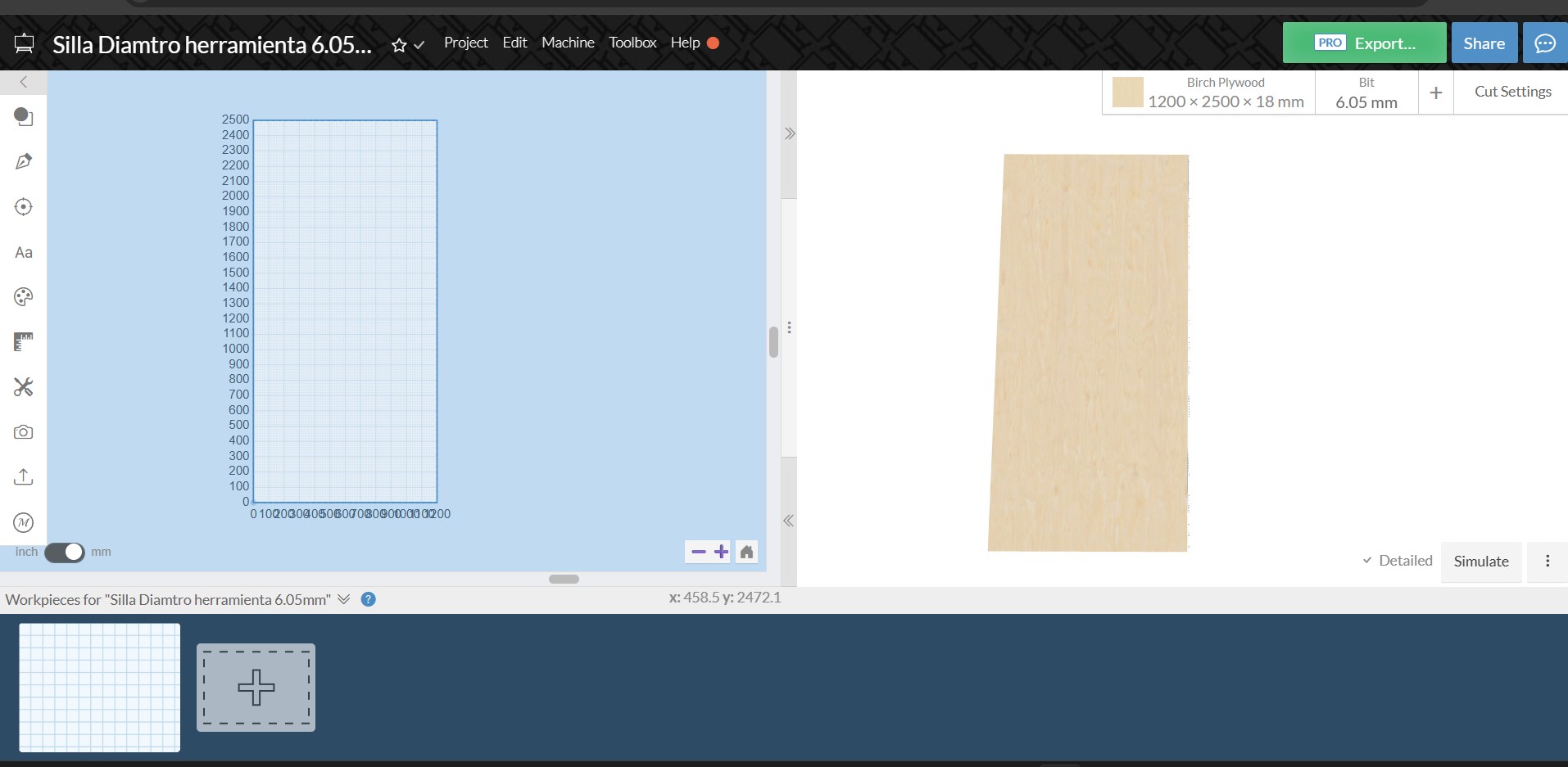
Easel Software Interface
Easel is a software used to design and generate toolpaths for CNC machines. Its interface is organized into several sections that allow users to design parts, configure materials, and simulate the machining process.
Top Menu Bar
At the top of the interface there is the main menu bar where the general project options are managed.
- Project: project management options.
- Edit: tools for editing the design.
- Machine: CNC machine configuration.
- Toolbox: additional tools and features.
- Help: access to documentation and support.
On the right side there are important buttons such as Export to generate the G-code and Share to share the project with others.
Tool Panel
On the left side of the interface there is a vertical toolbar that allows users to create and edit designs.
- Create geometric shapes.
- Insert text.
- Draw or edit vectors.
- Adjust dimensions.
- Import images or SVG files.
These tools allow users to build the design that will later be machined by the CNC machine.
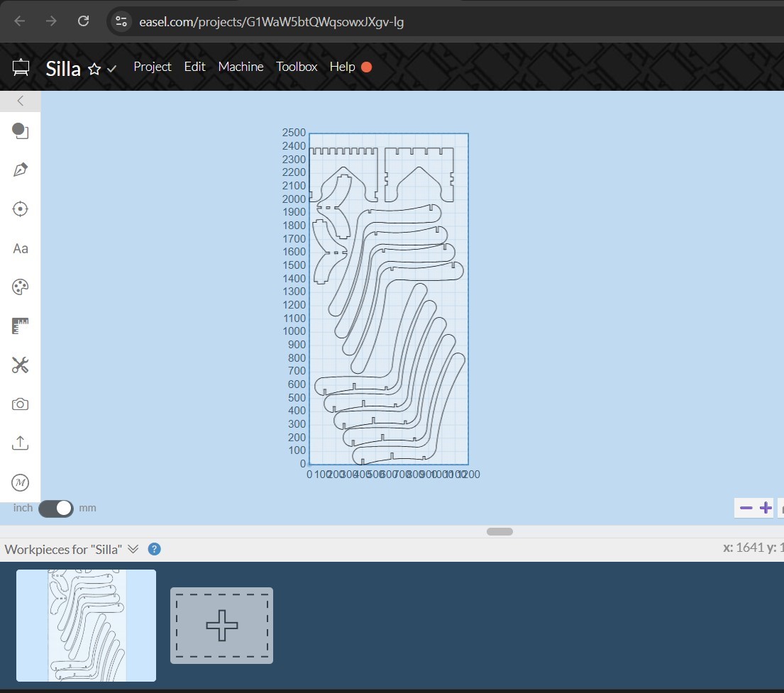
Workspace Area
The central part of the interface displays a grid that represents the CNC machine's working area.
- Place and organize design elements.
- Display material dimensions.
- Move and scale objects.
- Visualize the complete design before machining.
This workspace acts as the canvas where the entire design is created before sending it to the CNC machine.
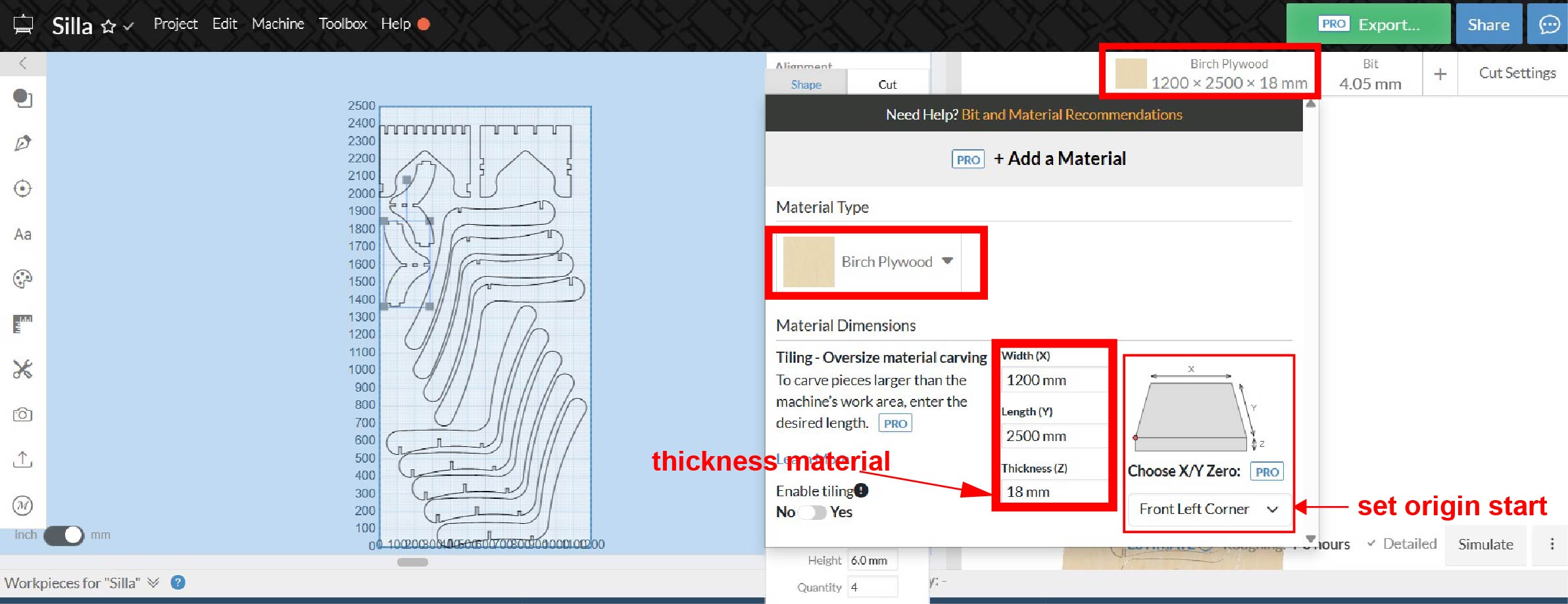
Material Settings Panel
On the right side there is a panel used to configure the material and cutting tool.
- Material: type of material to cut (for example Birch Plywood).
- Dimensions: board size, such as 1200 × 2500 × 18 mm.
- Bit: cutting tool diameter, for example 6.05 mm.
- Cut Settings: parameters used during machining.
Cut Simulation
The Simulate option allows users to preview how the CNC machine will perform the cutting process before executing it.
- Visualize the toolpath.
- Detect potential design errors.
- Preview the final machined result.
Workpieces Panel
At the bottom of the interface there is the Workpieces section where the material boards are managed.
- Add new material boards.
- Arrange parts within the board.
- Optimize material usage.
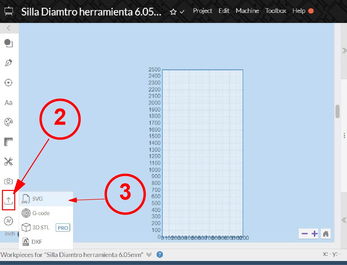
Once inside the software, the next step was to configure the material. In my case, I used a 4 × 8 ft plywood sheet with a thickness of 18 mm. After defining the material dimensions, I proceeded to upload the SVG file that was previously exported from Adobe Illustrator. To do this, I clicked on the Import button and selected the option Upload SVG File.
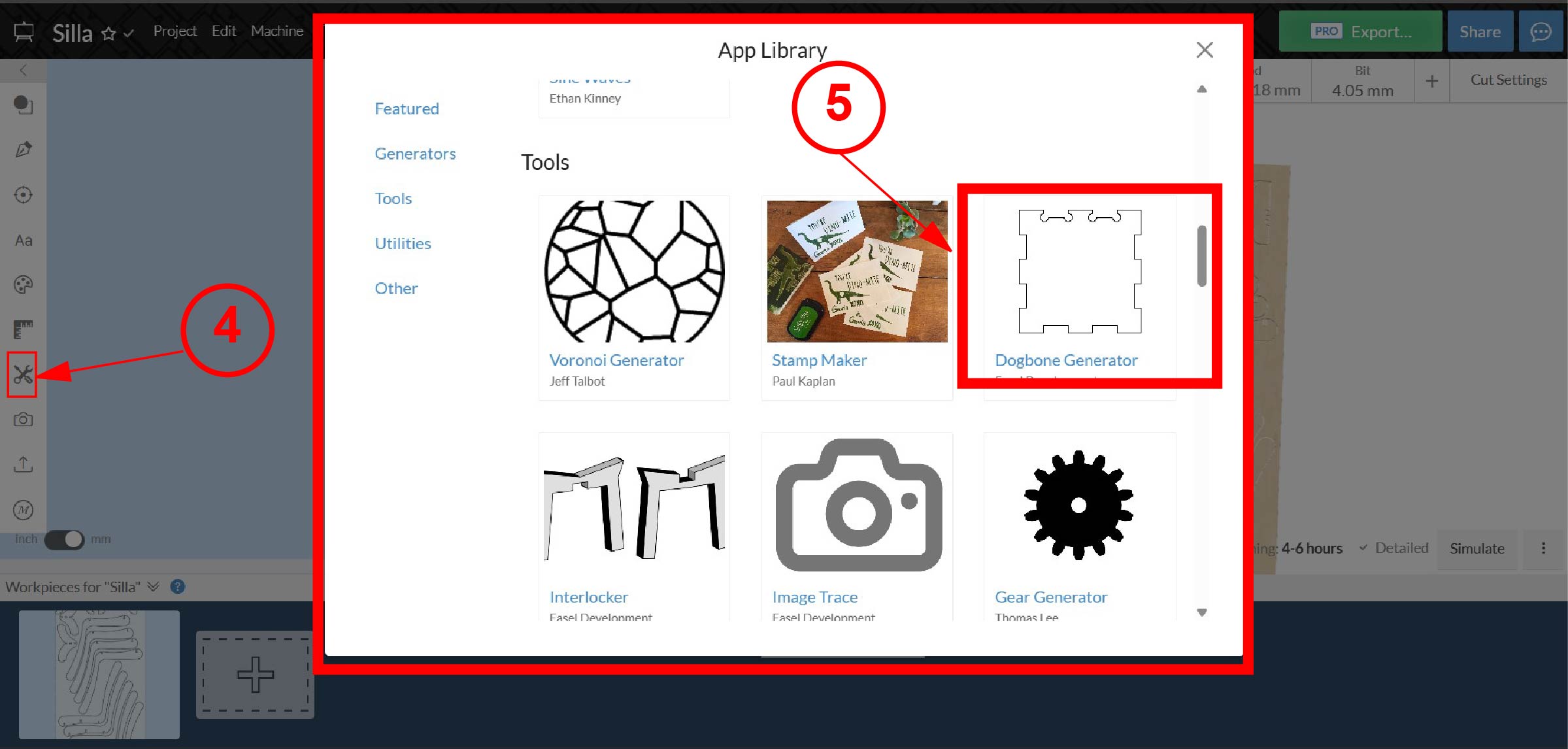
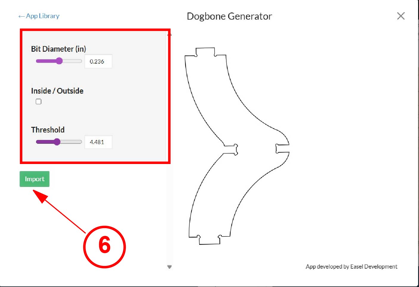
Once the file was successfully imported, I proceeded to create dogbone joints. These are small rounded cutouts added to the internal corners of the design. They are necessary because the milling tool has a cylindrical shape, which means it naturally leaves rounded internal corners during the cutting process. Without these dogbones, the pieces would not fit correctly during assembly since the slots would not allow square edges to enter properly.

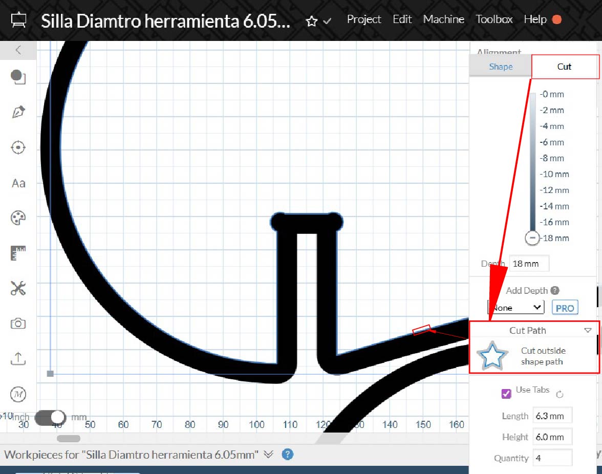
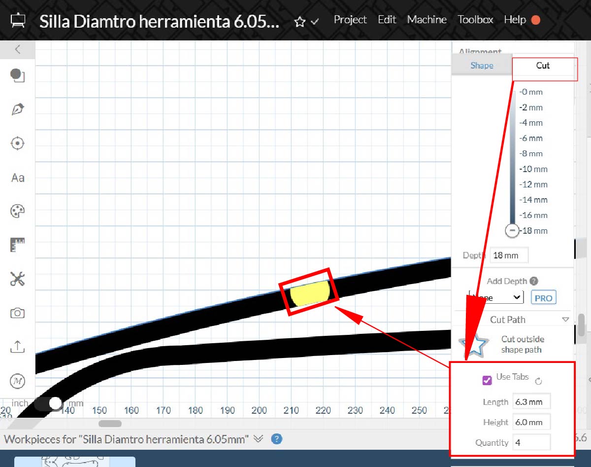
The next step was selecting the type of cut. In this case, I selected Cut Outside, which ensures that the milling tool removes material from the outside of the vector line. This allows the final dimensions of the pieces to remain accurate according to the original design. After defining the cutting type, I added tabs with dimensions of 6.3 mm in length and 6 mm in height. Tabs are small bridges that keep the pieces attached to the material sheet during the cutting process, preventing them from moving or detaching prematurely. I used these values to ensure the parts would remain stable during machining, especially since plywood sheets are not always perfectly flat.
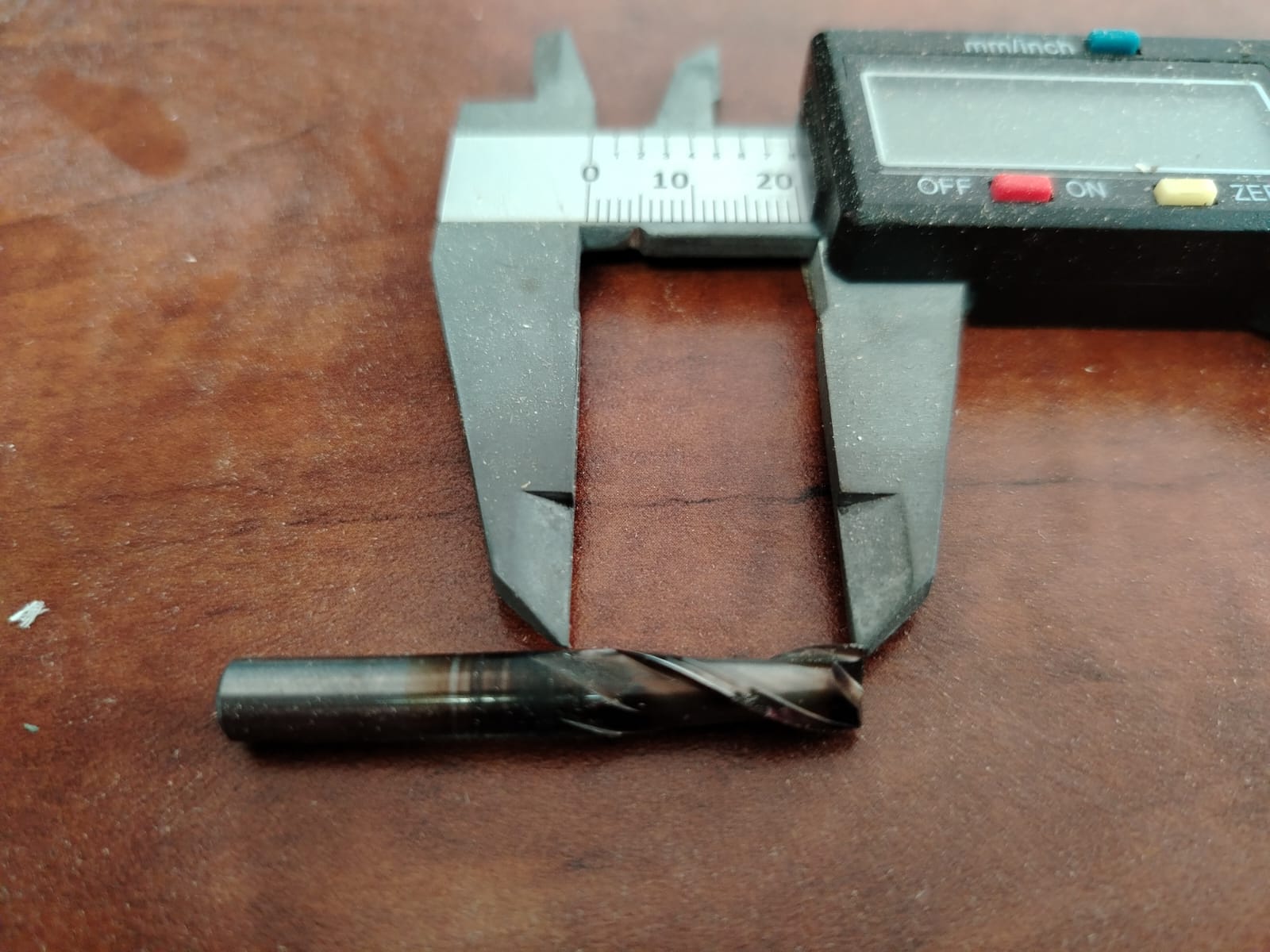
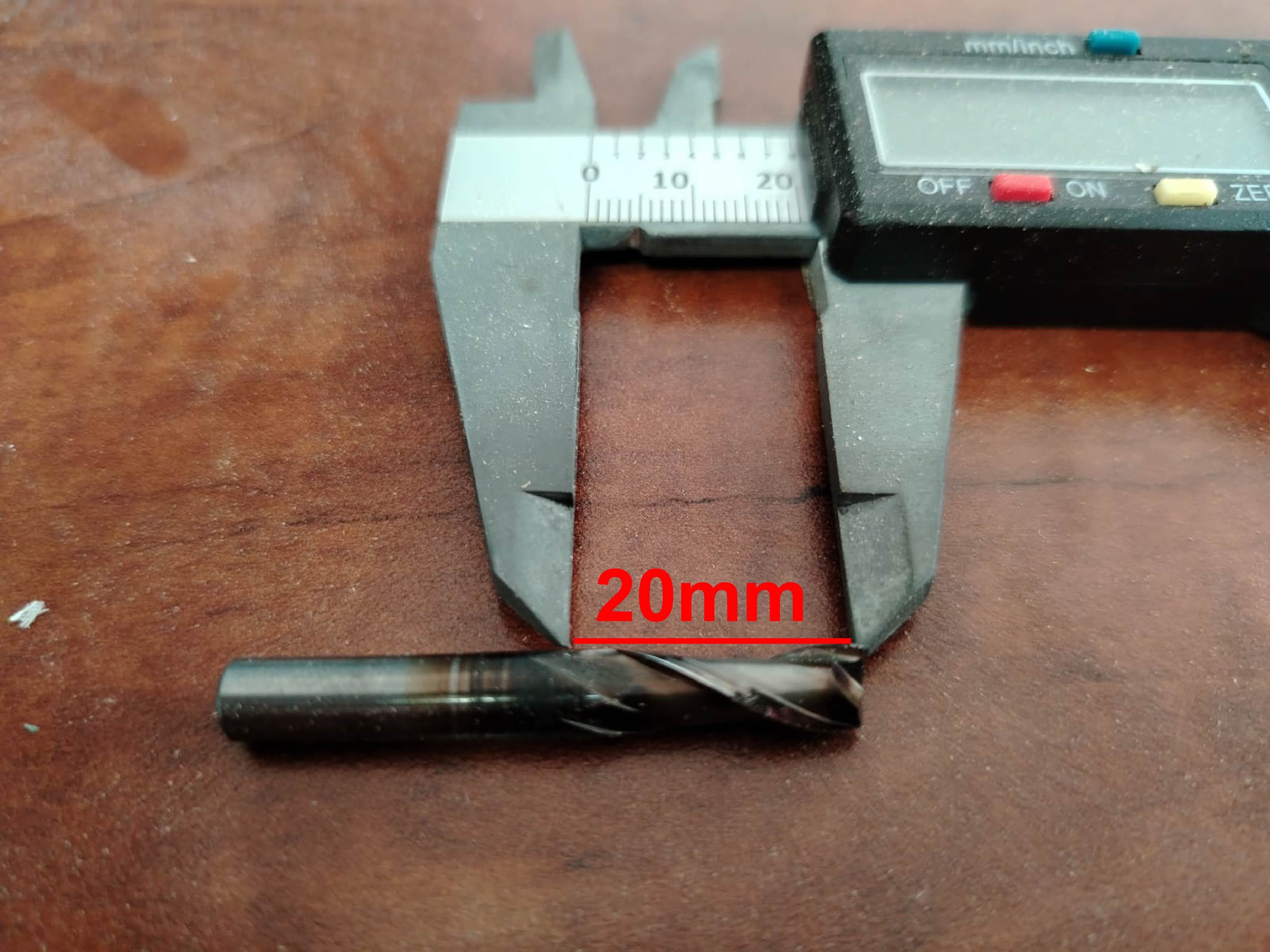
Next, I configured the cutting tool. For this project I used a 1/4 inch (6 mm) end mill with 2 flutes, which is a common tool for cutting plywood with CNC routers.
Finally, I configured the cutting parameters as shown in the following image.
CNC Cutting Parameters in Easel
The following parameters are configured manually in the Easel interface to control how the CNC machine performs the cutting process.
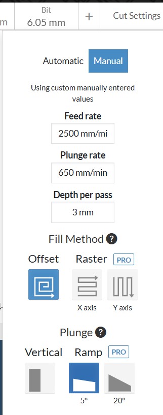
Manual Mode
The interface is set to Manual mode, which allows the user to define custom cutting parameters instead of using the automatic settings provided by the software.
Feed Rate
The Feed Rate is configured at 2500 mm/min. This parameter defines the speed at which the cutting tool moves horizontally along the X and Y axes while cutting the material.
Plunge Rate
The Plunge Rate is set to 650 mm/min. This value determines how fast the tool moves vertically along the Z axis when entering the material.
Depth per Pass
The Depth per Pass is configured at 3 mm. This means the tool removes 2 millimeters of material during each cutting pass until the full material thickness is reached.
Fill Method
The selected Fill Method is Offset. This method generates toolpaths that follow the contour of the shape toward the interior, creating parallel paths that efficiently remove material.
Plunge Type
The selected plunge type is Ramp 5°, meaning the cutting tool enters the material directly from above. Other options include Ramp, which allows the tool to enter the material at an angle to reduce stress on the tool.
Summary of Parameters
| Parameter | Value |
|---|---|
| Feed Rate | 2500 mm/min |
| Plunge Rate | 650 mm/min |
| Depth per Pass | 3 mm |
| Fill Method | Offset |
| Plunge Type | Ramp |
Once these parameters were configured, I proceeded to run the machining simulation to verify that all the toolpaths were correct and that there would be no errors during the cutting process.
After confirming that the simulation produced the expected results, I exported the file in .nc format. This file contains the G-code instructions required by the CNC machine to perform the cutting operation. The exported file was then ready to be transferred to the CNC machine to begin the machining process.
Proceso de corte CNC
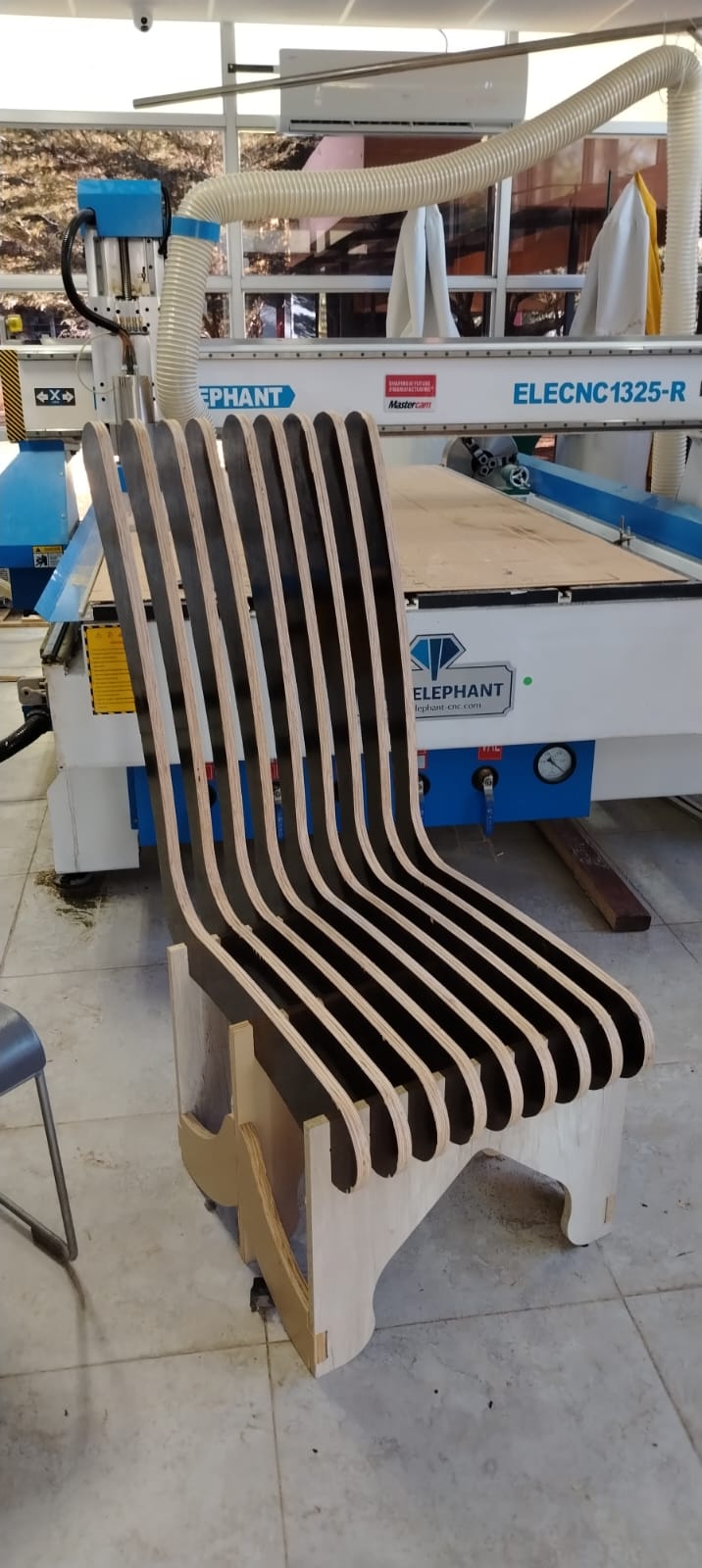
To manufacture my chair, I used the CNC router Blue Elephant ELECNC1325-R.
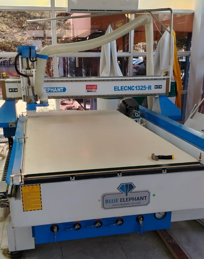
Blue Elephant ELECNC1325-R CNC Router
Technical specifications and supported materials
General Characteristics
- Machine Type: 4-Axis CNC Router
- Working Area: 1300 mm × 2500 mm (4 ft × 8 ft)
- Z Axis Travel: 200 – 300 mm
- Spindle Power: 3 kW Water-cooled spindle
- Control System: DSP Controller / Mach3 / NC Studio
- Motors: Stepper motors or Leadshine servo motors
- Work Table: T-slot table or Vacuum table
- Additional Feature: Rotary axis for cylindrical machining
Supported Materials
- Wood: Solid wood, MDF, plywood
- Plastics: Acrylic, PVC, ABS
- Foam: High density foam for molds and sculptures
- Composite Materials: Some industrial composite boards
- Soft Metals: Aluminum (with appropriate tooling)
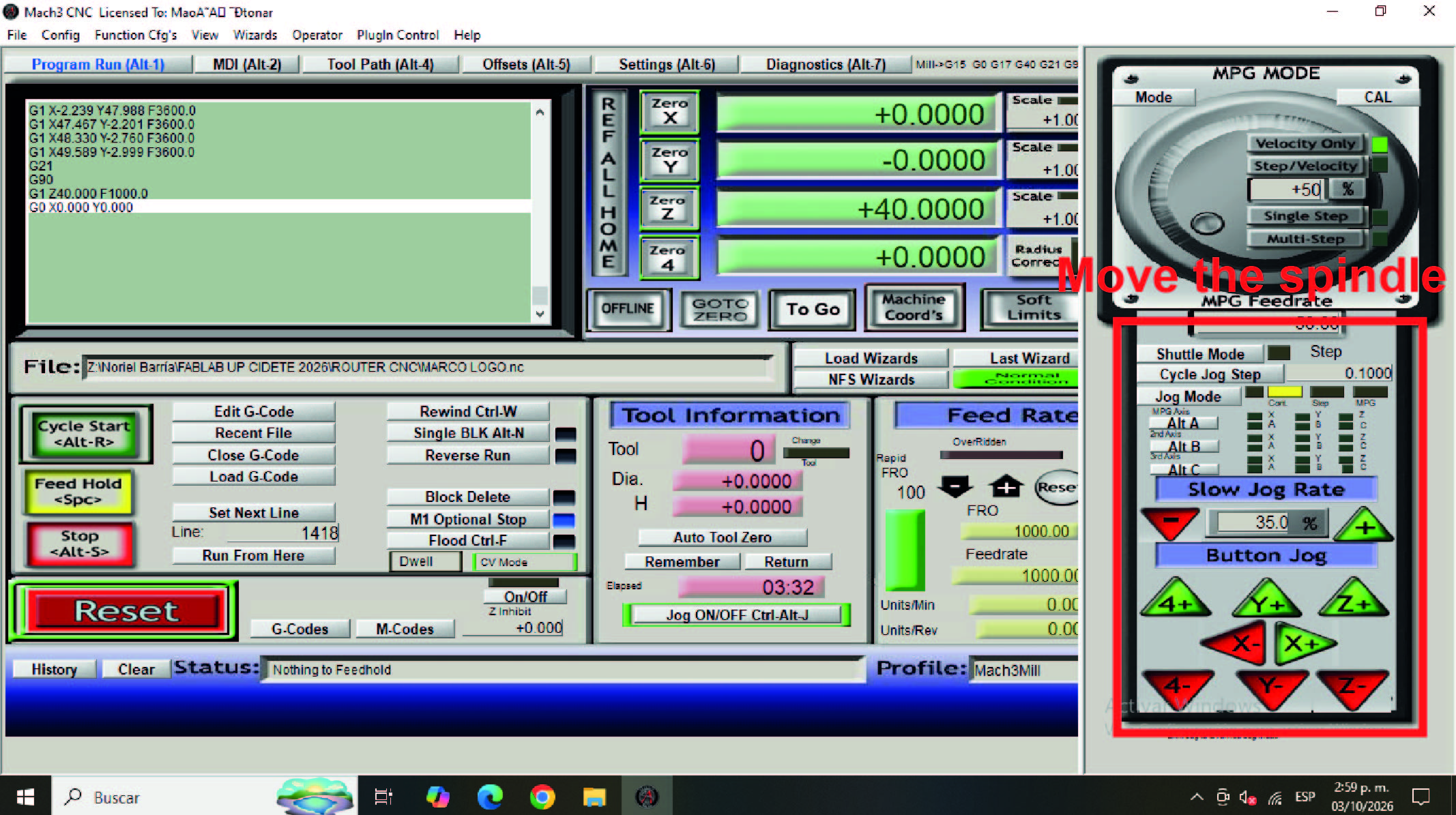
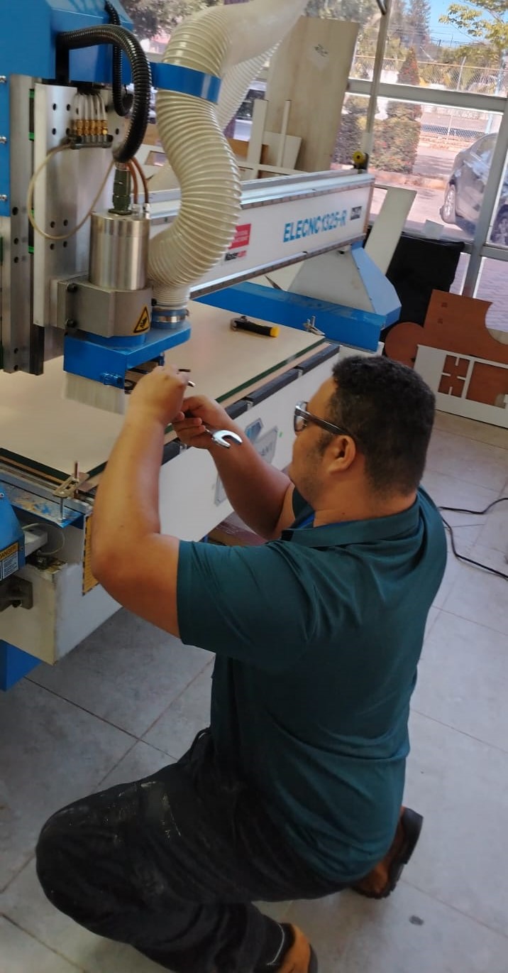
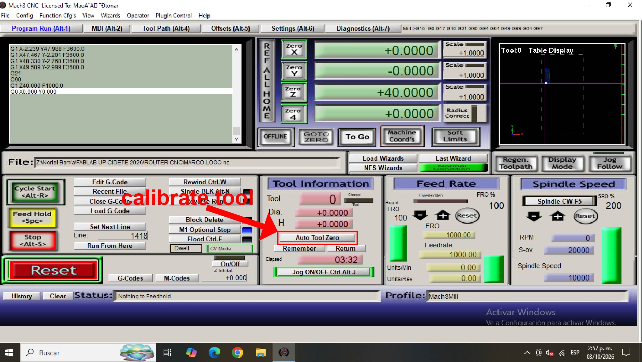
The first step was to turn on the CNC router. Once the machine was powered on, I launched the Mach3 controller software, which is the system currently used to operate this machine. After opening the software, I moved the spindle head to the front of the CNC router. This position allows easy access to install the cutting tool or end mill in the spindle, as shown below.
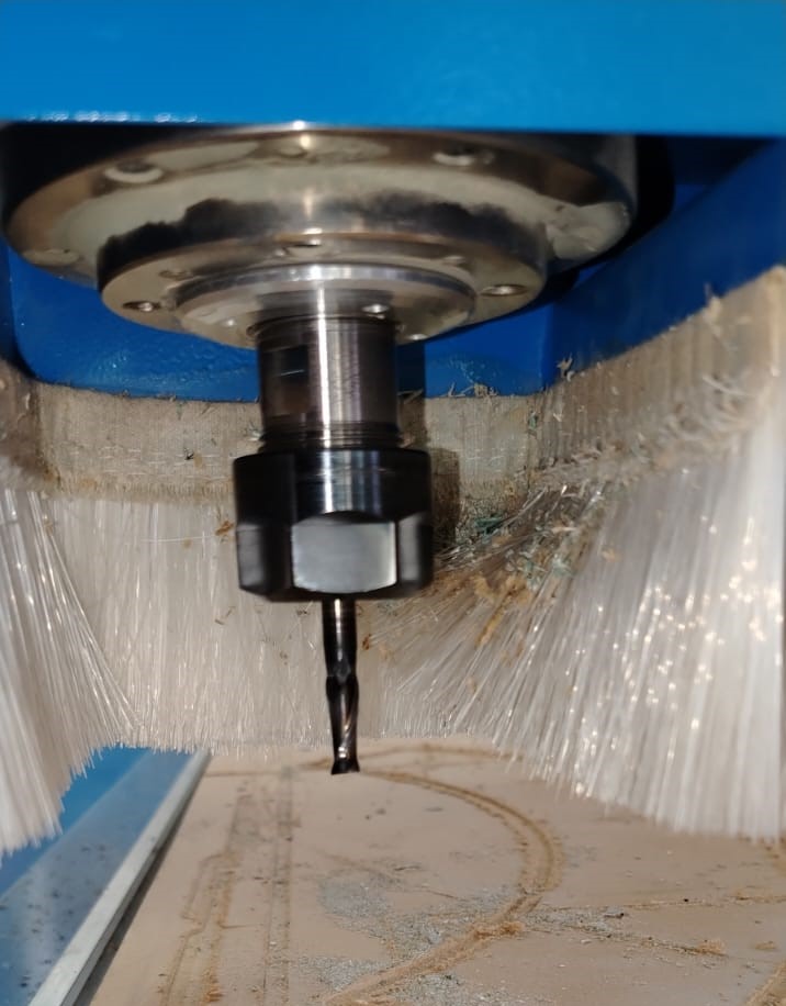
Once the spindle was positioned at the front, I proceeded to install the cutting tool (end mill) in the spindle.
After installing the cutting tool, I placed a 4 × 8 ft plywood sheet with a thickness of 18 mm on top of the CNC router sacrificial bed. To secure the material, I used mechanical clamps placed at strategic points to prevent the sheet from moving during the milling process. Additionally, the vacuum system of the machine was activated to provide extra stability and hold the plywood firmly in place.
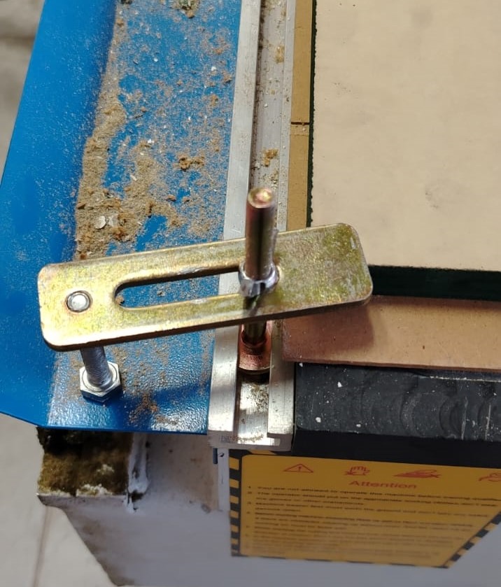
Once the material was fixed and the cutting tool installed, I proceeded with the initial setup of the machine. This included setting the work origin point and calibrating the Z-axis before starting the machining process.
Later, I had to cut the remaining pieces using another piece of material because unfortunately the 4 × 8 ft plywood sheet with a thickness of 18 mm was not enough to cut all the parts required for the chair. For this reason, I decided to use a leftover piece of material. This material was a 15 mm thick waterproof board.
The chair was originally designed to be manufactured using 18 mm material, and the joints were dimensioned based on that thickness. However, the remaining material I had available was only 15 mm thick. At that moment I was a bit worried because I did not want to spend money buying another sheet of plywood.
After carefully analyzing the design plans, I realized that the thickness difference would not affect the assembly of the front and rear legs of the chair. Because of this, I decided to manufacture those specific parts using the 15 mm material instead of the original 18 mm sheet. It was either buying new material or taking this opportunity and adapting the design.
Below are the pieces that were cut separately using the 15 mm material.
Cutting the remaining parts:
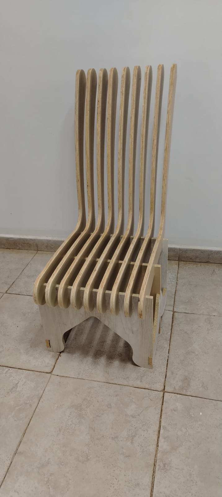
Once the cutting process was finished, I proceeded to assemble all the parts. I did not use glue or nails; all the pieces fit together perfectly thanks to the press-fit design. Below I show the final result of my work.

During this process, I learned how to perform 2D machining for the manufacturing of my chair. I also became familiar with several important machining concepts such as flutes, feed rate, plunge rate, depth per pass, tabs, and dogbones.
Learning these concepts has been very valuable for me because it allows me to gradually acquire new knowledge and improve my understanding of the CNC machining process as I continue working with these tools.
Dowload File
Mission accomplished! 😊