Group assignment
Here I share the link to my group assignment.
The final reflection can be found at the end of the page.t
indivual assignment
Objective
Design and fabricate a parametric construction kit using a laser cutter, considering material thickness and kerf.
Concept Development
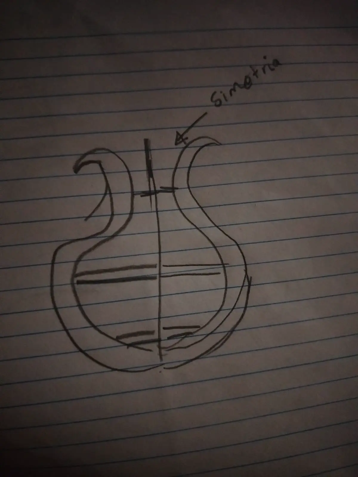
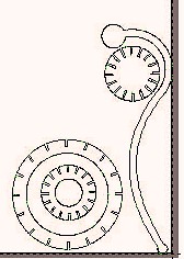
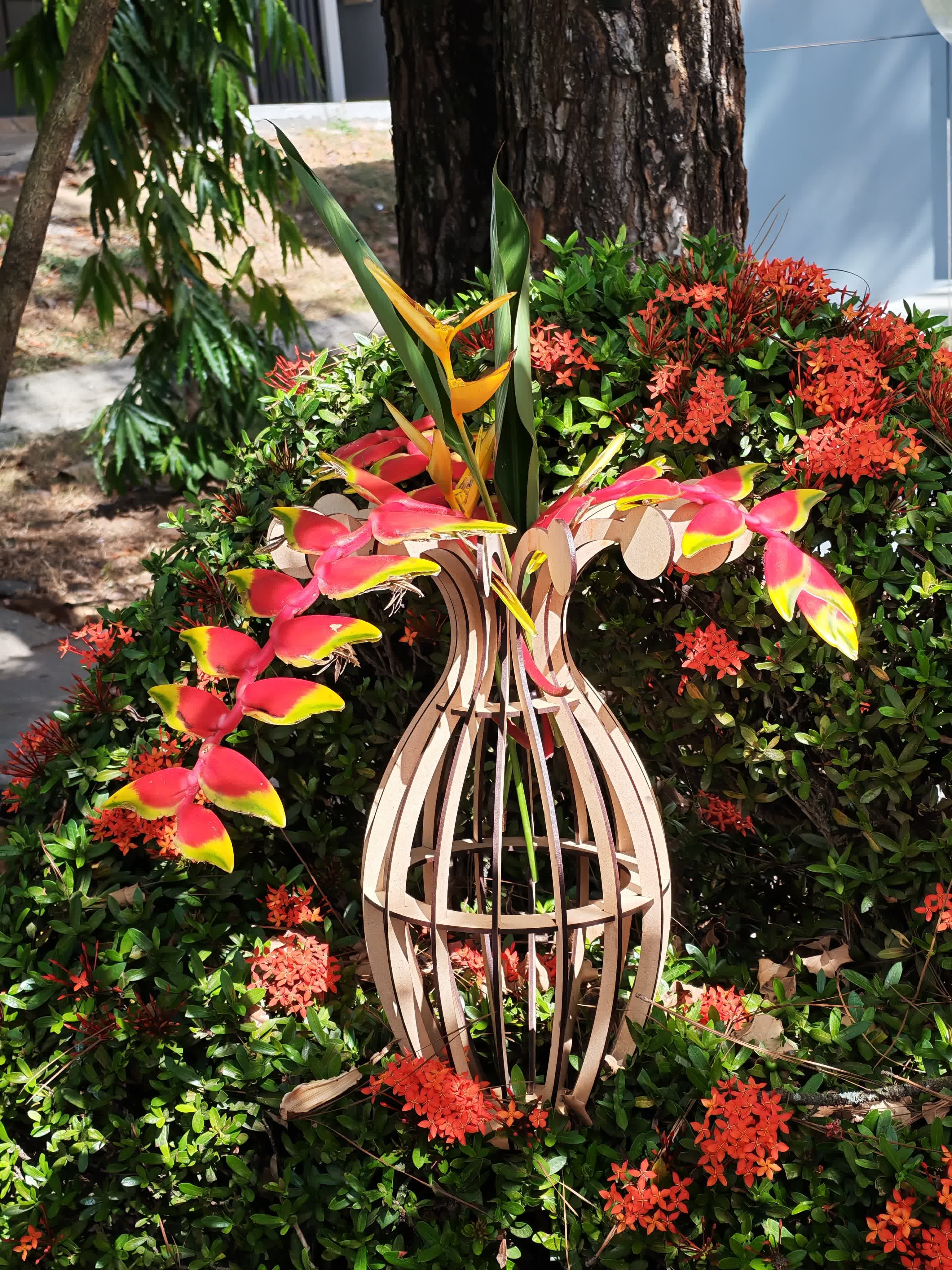
The design process started with a hand-drawn sketch to define proportions and functionality. The final object can be used as a decorative planter.
Concept Sketch Image
Parametric Design in Fusion 360
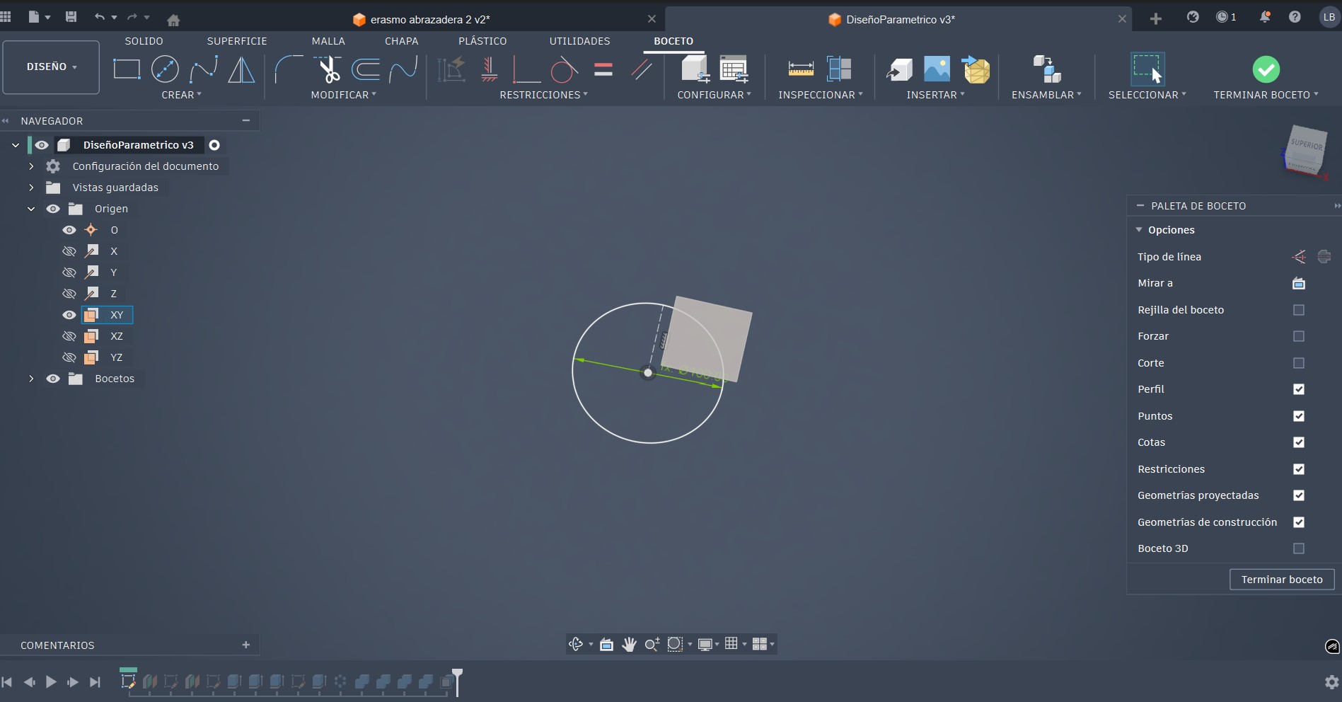
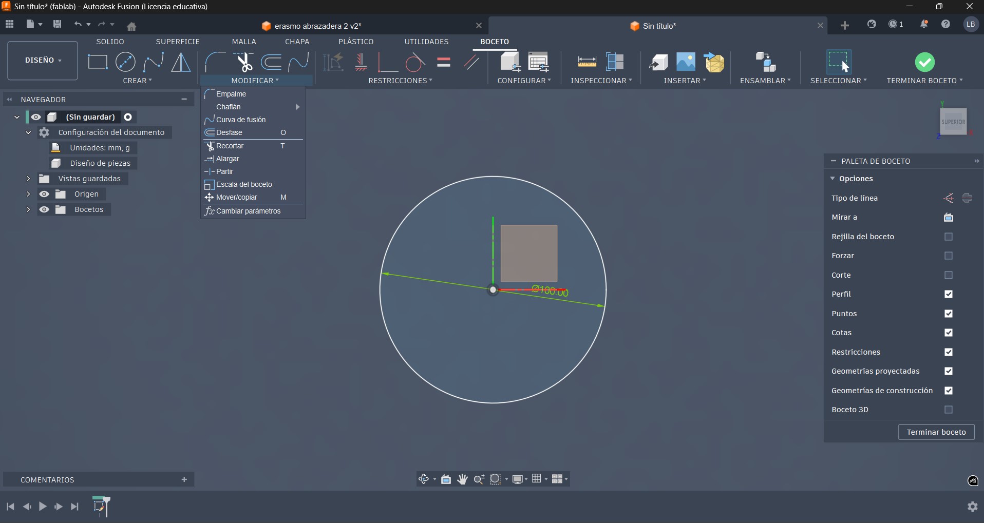
Base Sketch
- Sketch created on the XY plane
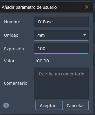
- Base circle with parameter D1Base = 100 mm
Base Sketch Screenshot
define parametric value D1Base
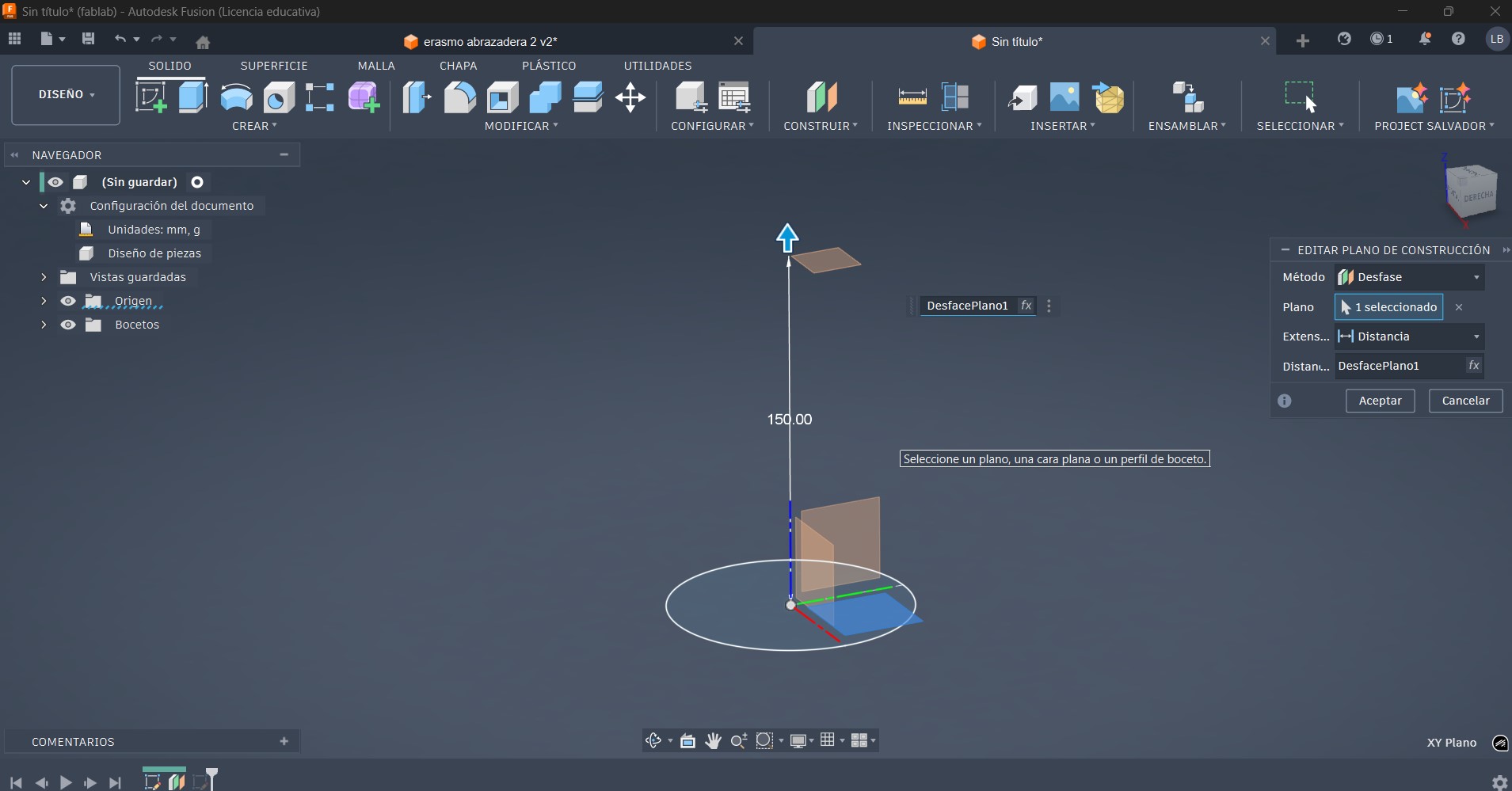
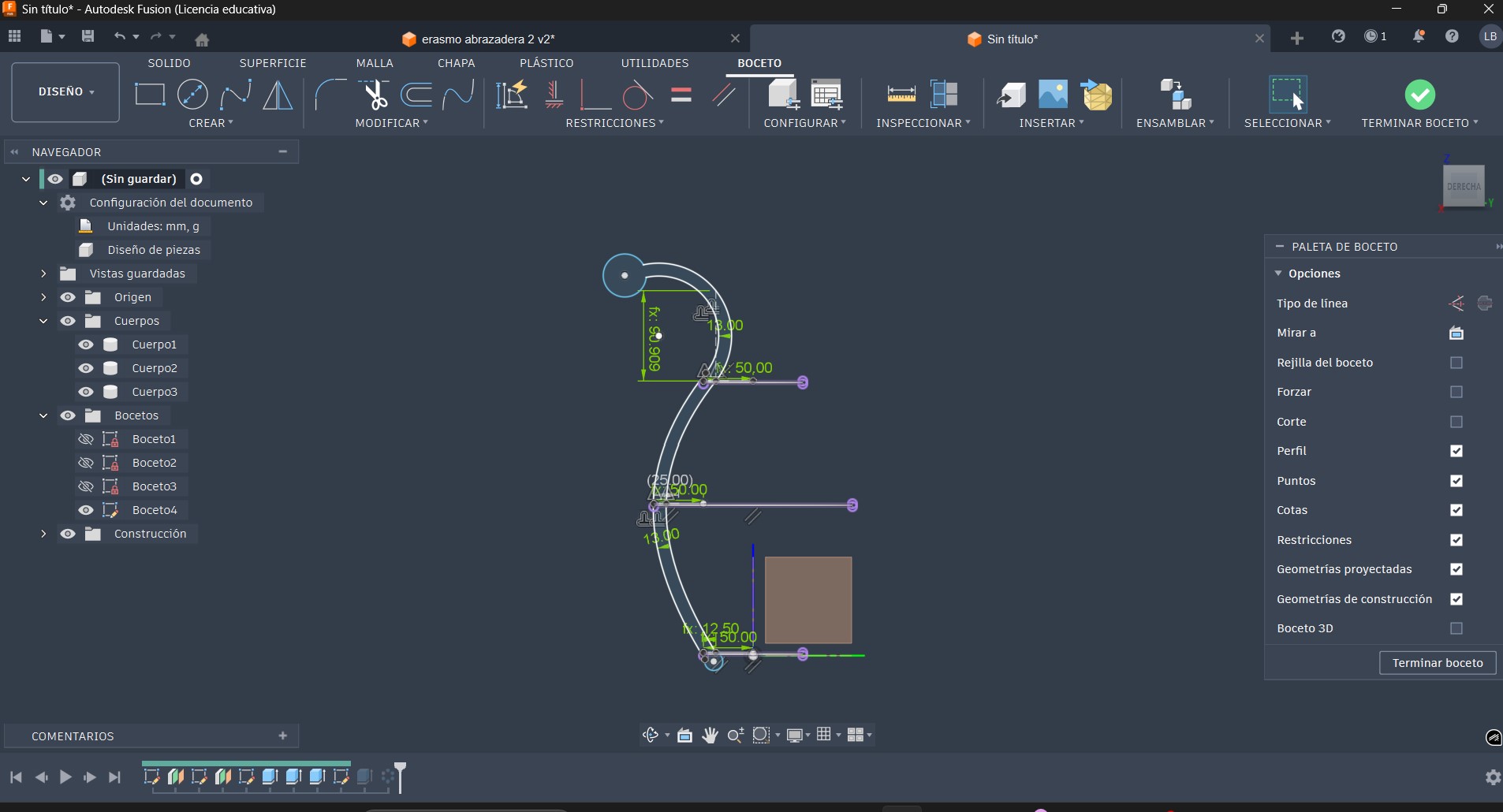
Construction Plane
- Offset construction plane at 150 mm Midpoint of our vase.
- in this new plane draw Two concentric circles fully constrained
Construction Plane Screenshot
Sketch Construction Plane Screenshot

Material Thickness
A user parameter named Material_Thickness = 3 mm was defined and used for all extrusions to match the real laser-cut material.
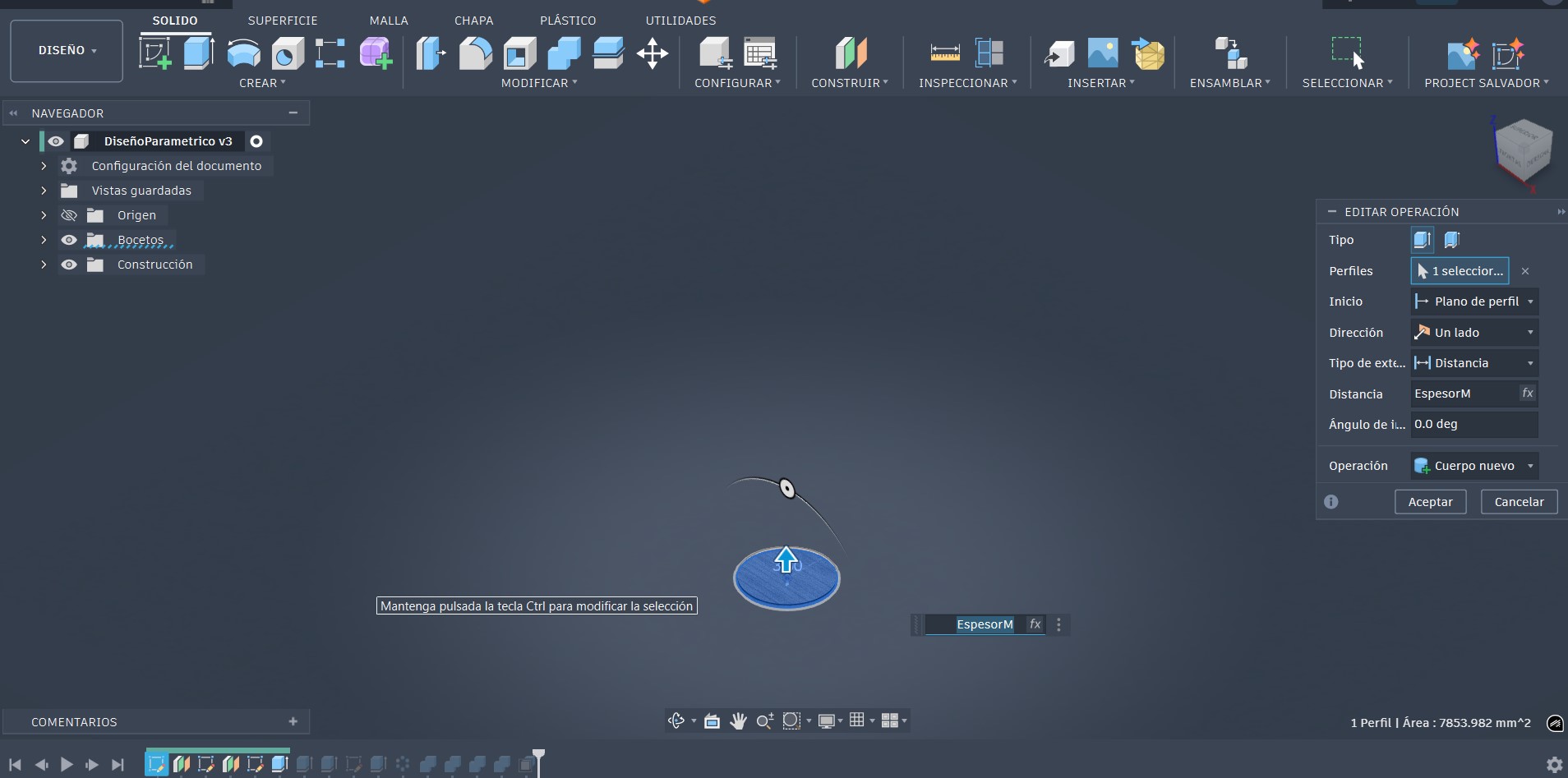
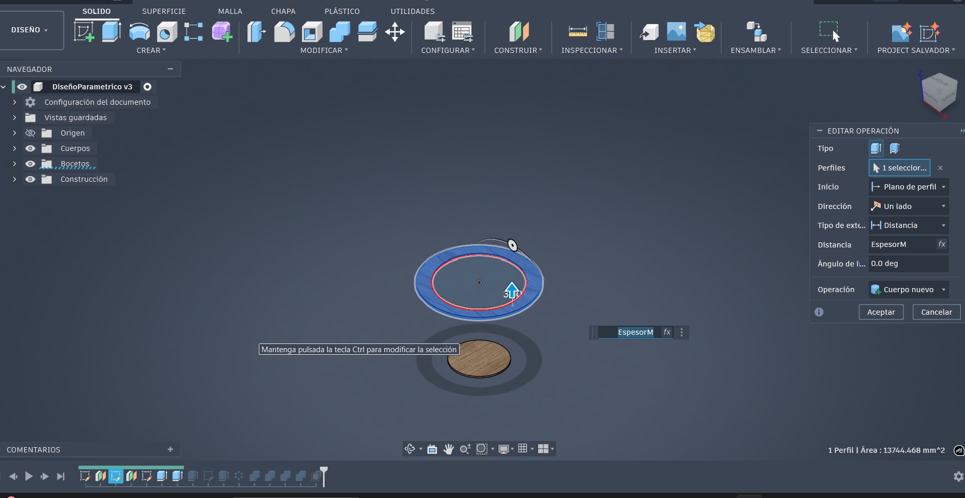
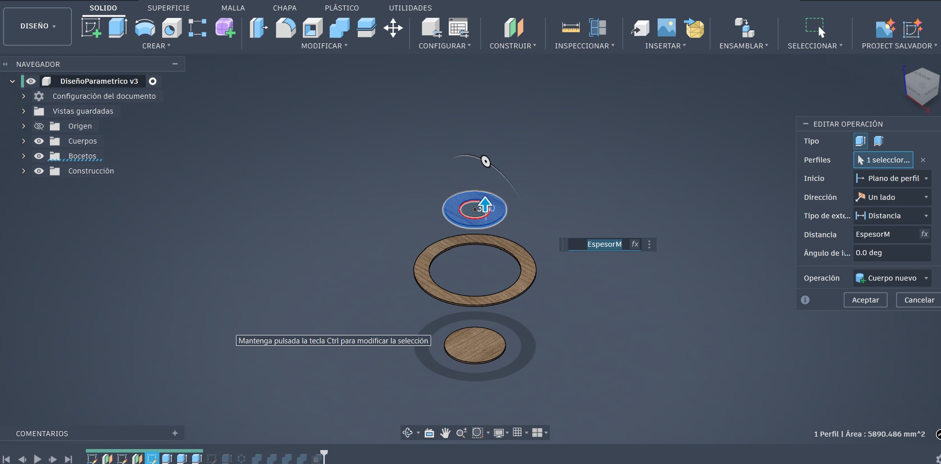
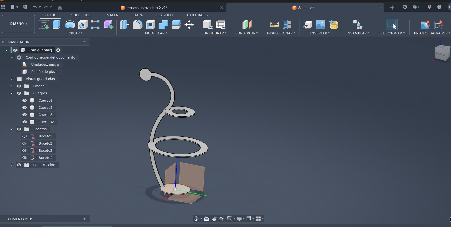
Extrusion Process
Profile Extrusion
At this stage of the modeling process, the previously defined profile is extruded using the user parameter EspesorM, which has an assigned value of 3 mm. This parameter represents the actual thickness of the material that will be used during the laser cutting process.
The same EspesorM = 3 mm value is applied consistently to all extrusions throughout the design, ensuring uniform thickness, dimensional accuracy, and proper press-fit assembly.
Profile Extrusion Using EspesorM
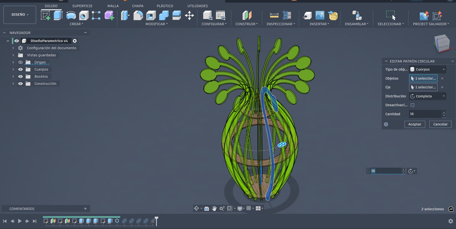
Side Panels and Circular Pattern
At this stage of the design process, a new sketch was created on the vertical plane in order to define the side geometry of the part. This sketch was used to establish the required dimensions and constraints to complete the overall shape and ensure proper integration with the rest of the model. The resulting sketch applied to the design can be observed in the image below.
Sketch profile used to define the side geometry of the part
Extruded sketch profile used to generate the side geometry
A circular pattern operation was applied to the component to uniformly replicate the geometry around the central axis, ensuring dimensional consistency across all instances.

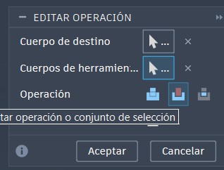
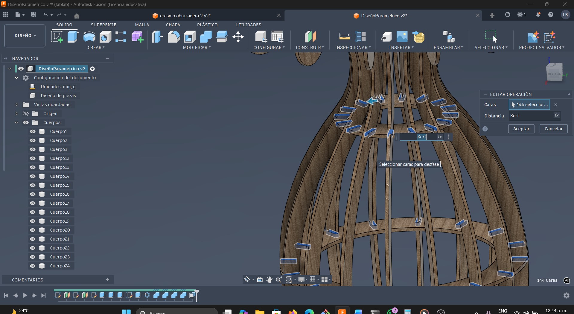
Joints and Kerf Compensation
-
At this stage, the joints required for inserting the lateral components were generated. To accomplish this, the Combine tool was used and configured as follows: first, the target body where the cut would be applied was selected. Then, the body intended to be used as the cutting tool was chosen. Once both bodies were selected, the operation type was set to Cut, and the Keep Tools option was enabled in order to preserve the cutting body. Finally, the operation was executed by confirming the settings.
-
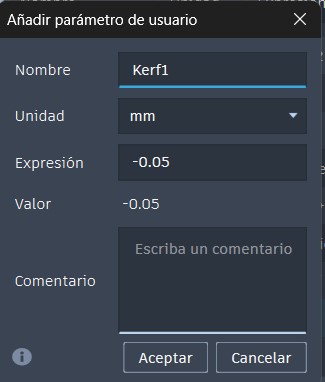
The kerf value was integrated into the design through a user-defined parameter. Although the initial value was established based on prior experience with the laser cutter, the parameter was kept editable to allow for subsequent adjustment after calibration tests, ensuring dimensional accuracy and proper assembly.
Preparing the design for laser cutting
At this stage of the process, the 3D model is already fully defined. The next step consists of translating this design into a physical object using the laser cutting technique. For this purpose, the same 3D design software, Fusion 360, was used, taking advantage of its tools to generate 2D drawings from the three-dimensional model.
-
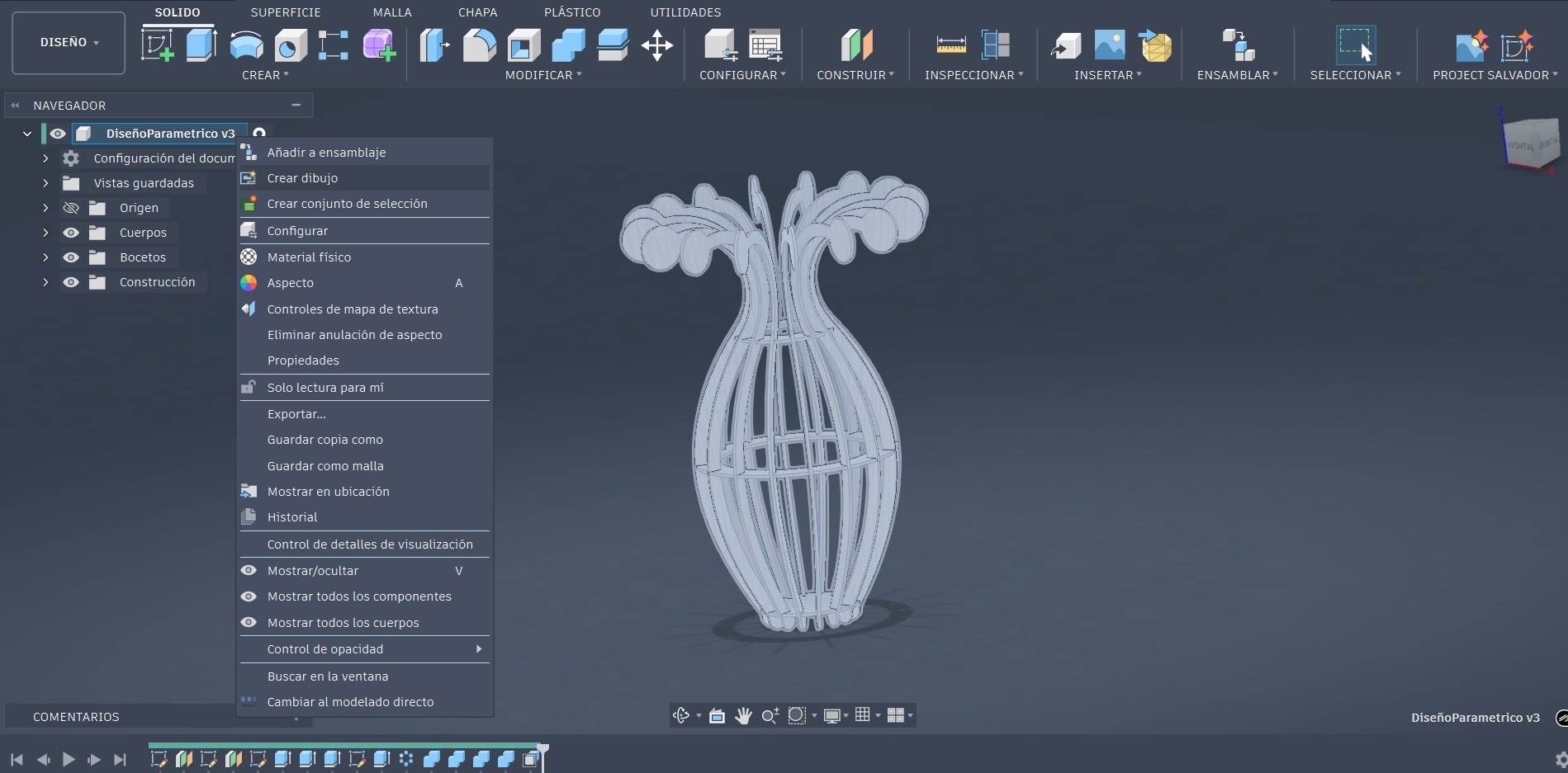
Within the Design workspace in Fusion 360, the Create menu was accessed.
-
he option Create Drawing → From Design was then selected.
-
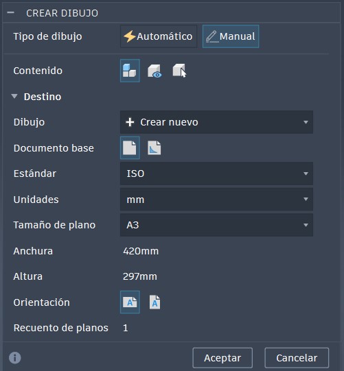
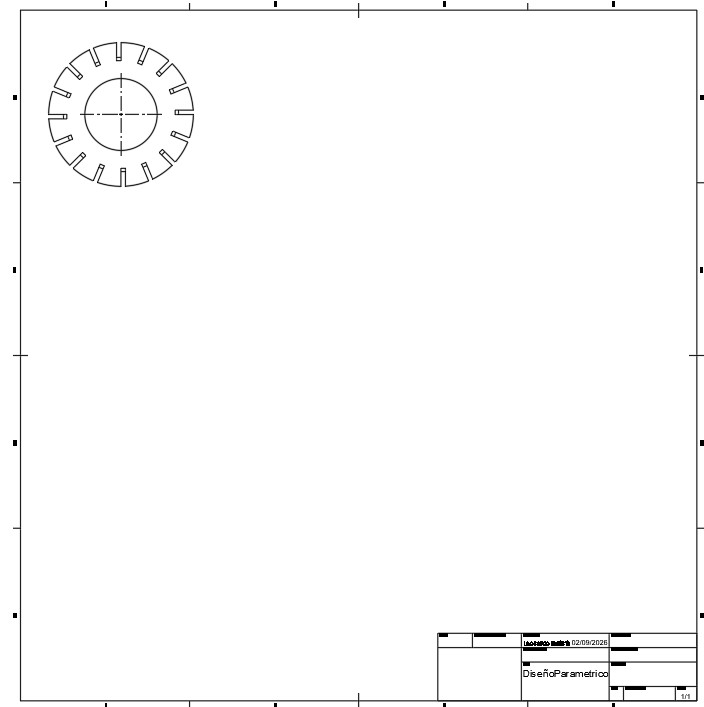
Once this step is completed, a window titled Create Drawing is displayed. In this dialog box, the drawing sheet size can be configured. For this project, the Custom option was selected, setting the sheet dimensions to 500 × 500 mm (equivalent to 50 × 50 cm), which is sufficient to generate the required design drawings. After confirming the settings, the corresponding drawing sheet was automatically created.
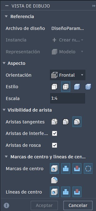
Fusion 360 drawing interface
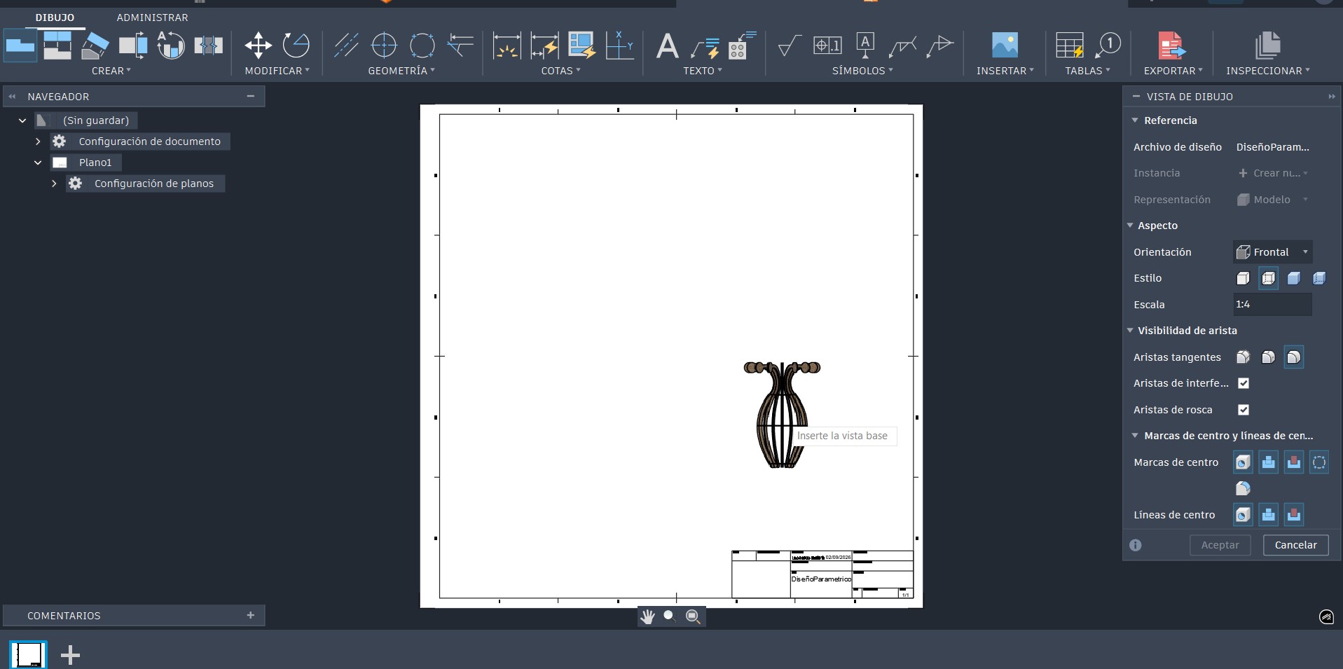
As observed on the right side of the Fusion 360 drawing interface, a configuration panel is displayed, allowing the adjustment of various drawing parameters such as view orientation and scale. For this project, the Top view was selected and the scale was set to 1:1, ensuring that the drawing represents the real dimensions of the design. This configuration allows the accurate extraction of the ring-shaped components, preserving their original dimensions and facilitating their proper preparation for the laser cutting process.
-
Top view of the design
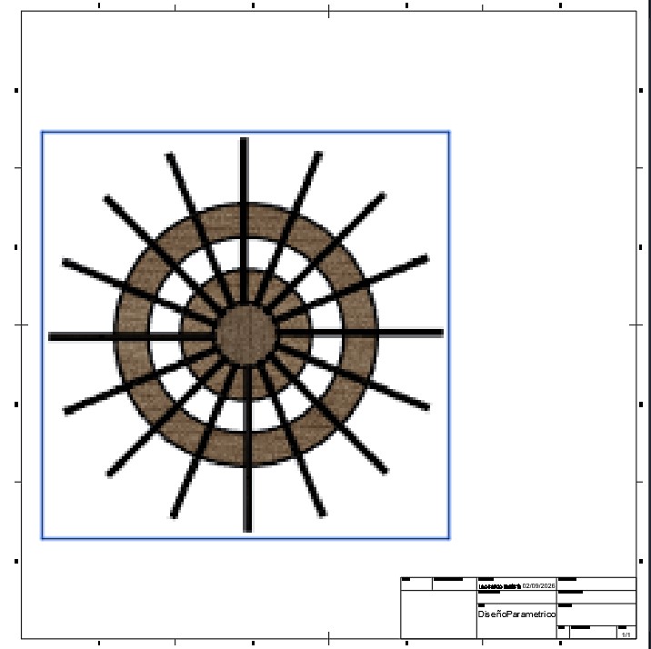
To obtain only the part intended for laser cutting, it is necessary to manage the visibility of the bodies within the Browser in Fusion 360.
As shown in the left panel of the interface, within the DiseñoParamétrico component, the Bodies folder contains all the solid bodies that make up the design. At this stage of the workflow, all bodies that were not part of the piece to be manufactured were hidden using the visibility (eye) icon, leaving visible only the body corresponding to the desired geometry.
This procedure allows the part to be visually isolated within the drawing environment, ensuring that only its geometry is projected in the selected view. As a result, the generated 2D drawing contains exclusively the contour of the required part, preventing interference from other model elements and facilitating proper preparation for export and subsequent laser cutting.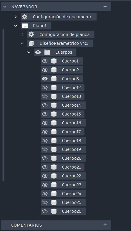
This procedure was repeated individually for each of the parts to be manufactured using the laser cutting process, ensuring that each component was properly isolated and prepared for subsequent export and fabrication.
The resulting file was organized in this manner. It is important to note that only one lateral part was required, as all the others are identical. Therefore, a single instance of the part was prepared, and the remaining copies were replicated directly within the laser cutting software, optimizing both preparation time and material usage.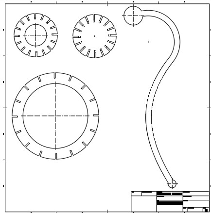
Once this process was completed, the file was exported in DXF format, which is compatible with the laser cutter control software and preserves the required 2D geometry with dimensional accuracy.
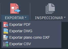
The DXFfile was saved to a USB drive, and the design was then transferred to the laser cutter for fabrication.
Laser Cutting Process
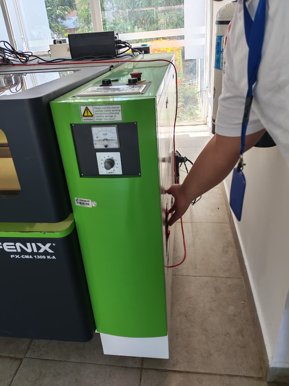
Operating of the laser used
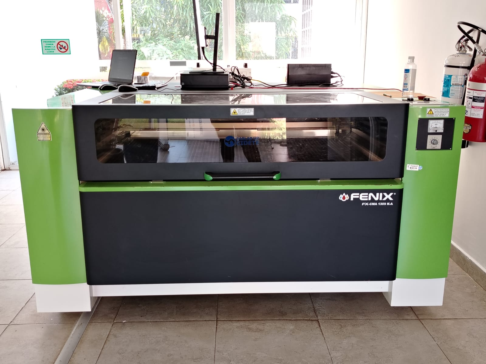
For the laser cutting process, I used a Fenix brand laser machine, model FX-CMA 1309. is a CO2 laser cutting and engraving machine designed for digital fabrication and prototyping applications. It is commonly used for cutting and engraving non-metallic materials such as acrylic, wood, MDF, cardboard, leather, and similar substrates.
This type of machine typically features a large working area of approximately 1300 × 900 mm, allowing the fabrication of medium to large-scale parts in a single operation. It operates using a CO2 laser tube, which generates a focused laser beam suitable for both cutting and engraving processes.
The system is controlled via dedicated laser cutting software, compatible with vector file formats such as DXF, enabling seamless integration with CAD tools like Fusion 360. Additionally, it includes essential subsystems such as air assist, water cooling, and fume extraction, which are required to ensure cut quality, operator safety, and proper machine operation.
The laser system uses a set of reflective mirrors to redirect the beam generated by the CO2 laser tube toward the laser head. At this point, a focusing lens concentrates the beam into a precise focal point on the material surface, generating the energy density required to melt or vaporize the material, thereby enabling the cutting process.
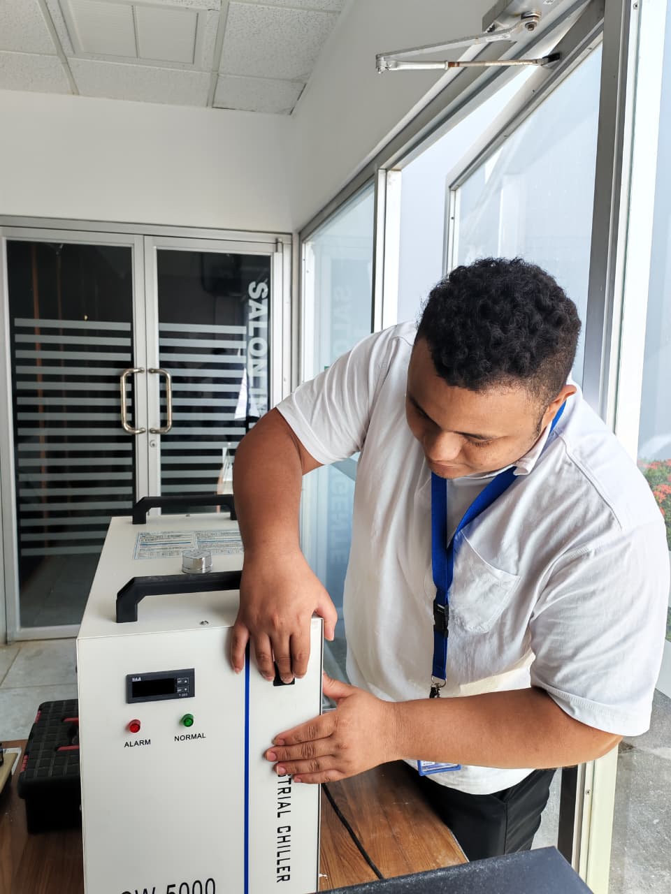
Powering on the equipment
-
First, the cooling system (chiller) is powered on.
-
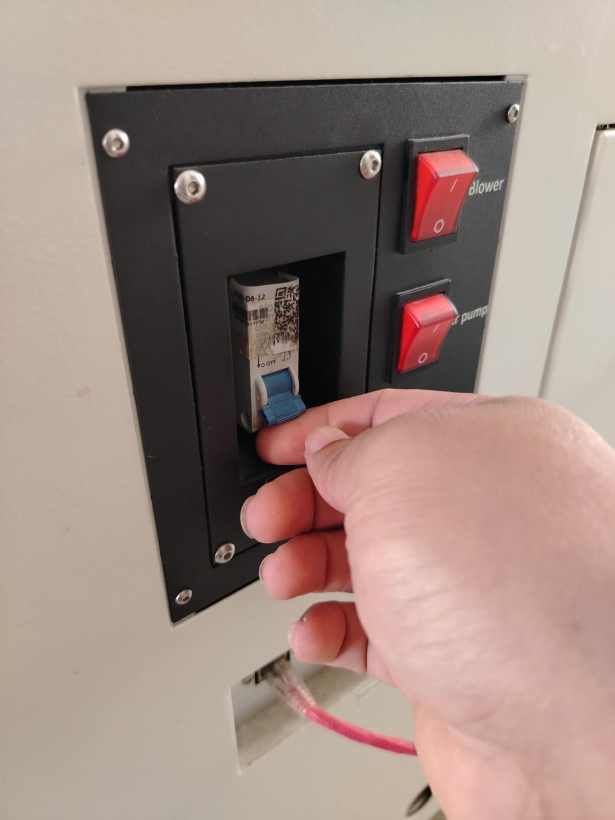
Power on the exhaust system
-
Power on the air assist system
-
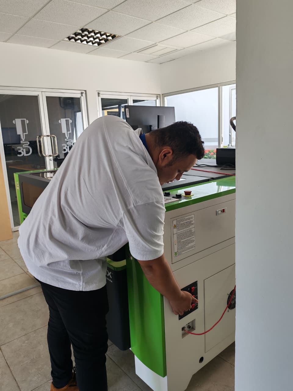
Power on the laser machine and turn the emergency button
-
Start the control software
Power on the computer
Open the laser control software. SmartCanve
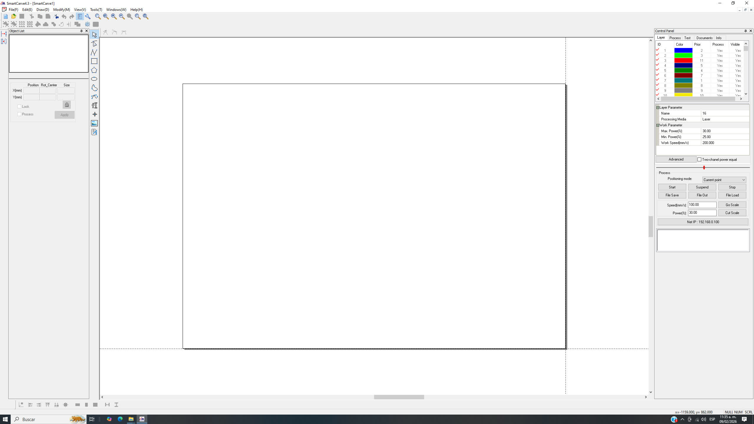
The SmartCarve interface is organized into several main areas. At the center is the workspace, where the canvas representing the laser machine bed is displayed and where the designs to be cut are placed and edited. At the top, the menu bar and toolbars provide access to functions such as opening files, drawing, editing objects, zooming, and configuring program options.
On the left side, the tools panel and object list allow the user to select, move, and modify design entities, as well as view their position and size properties. On the right side, the control and layer panel is used to assign colors, define cutting parameters such as power, speed, and number of passes, and manage the process of sending the file to the laser machine.
This is the software interface.
Load the cutting file (DXF).
To open or load a file, we go to the File menu and select the Import option. This action opens a file browser window, where we navigate to the location of the desired file, select it, and confirm by clicking Open. Once this process is completed, the design is automatically loaded into the software’s workspace, where it is available for visualization, adjustment, and further configuration for the laser cutting process.
Once the file has been successfully loaded into the software, the next step is to configure the laser cutting parameters. These values must be adjusted according to the material being used and its thickness.
In this case, 3 mm MDF was used, for which the following parameters were set: 50% maximum power, 45% minimum power, and a cutting speed of 15 mm/s.
MDF of 3mm Thickness
value of power and speed cutting
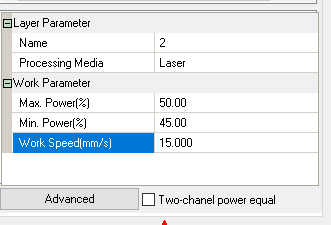
It is important to note that the layer section allows the use of different colors, making it possible to assign specific parameters to each set of geometries. This enables each layer to be configured with independent power and speed values based on the requirements of the design.
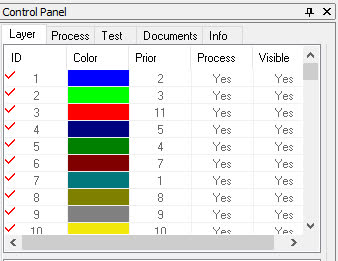
Additionally, the software allows users to define the cutting order, establishing a specific sequence for the cutting process. For this project, no cutting priority was assigned; instead, a single layer was selected and its corresponding power and speed values were manually adjusted.
-
send file to the machine
Once all parameters have been configured in the software, the material is placed on the laser machine bed, ensuring that it is properly aligned and fully supported. The cutting origin is then set, defining the starting point from which the machine will begin the cutting process.
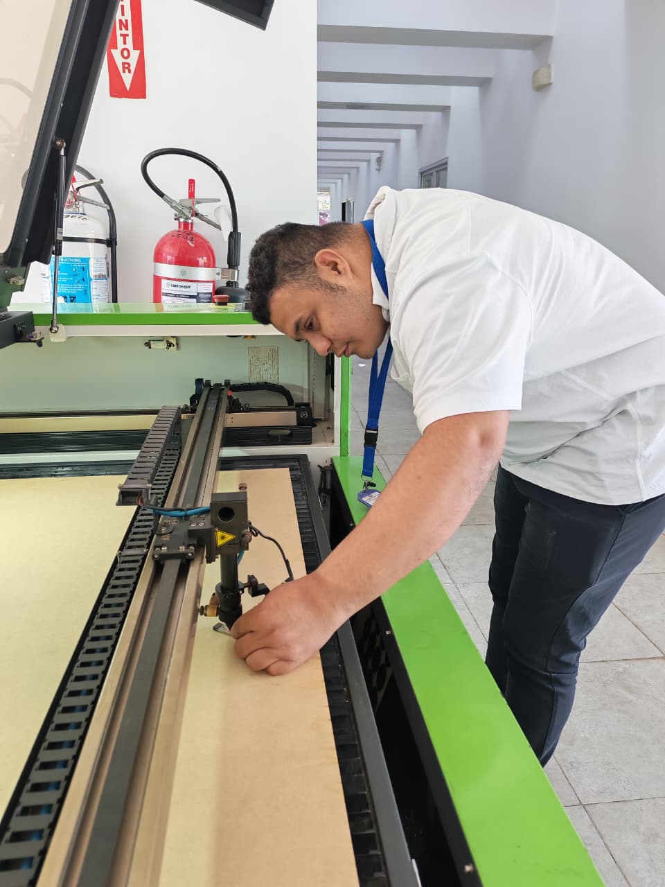
Next, the distance between the laser nozzle and the material is adjusted to approximately 5 mm, in order to ensure proper beam focus and accurate cutting.
After verifying all these settings, the design is sent from the control software to the laser machine, leaving the system ready to start the cutting operation.
Ready?, Starting Cut
Laser Cutting Video
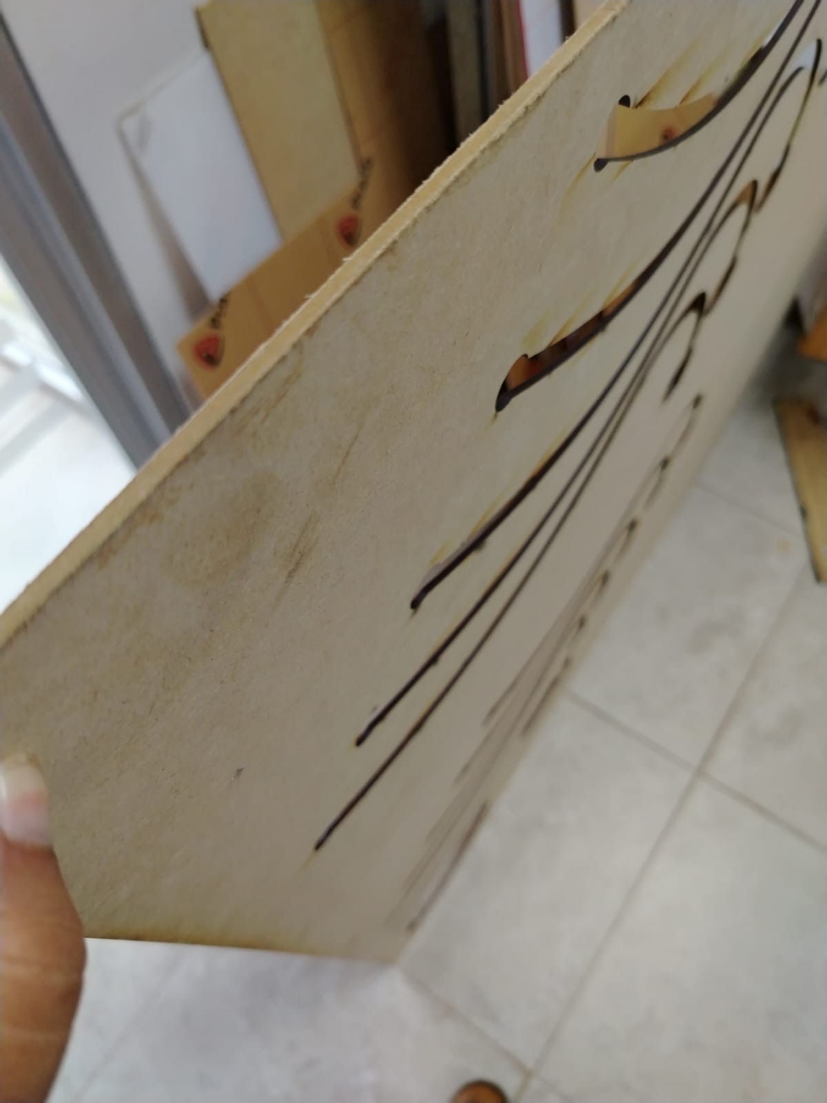
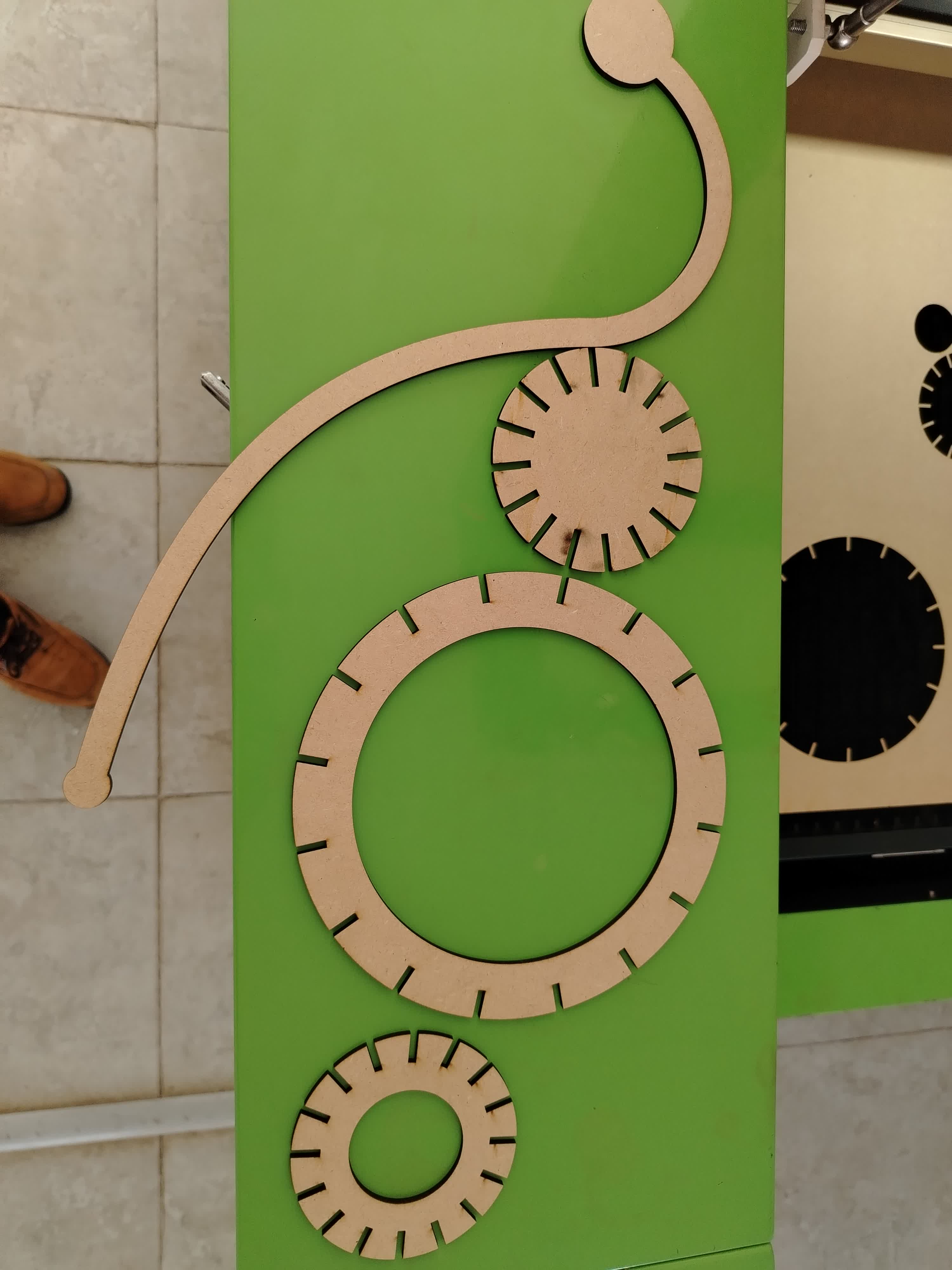
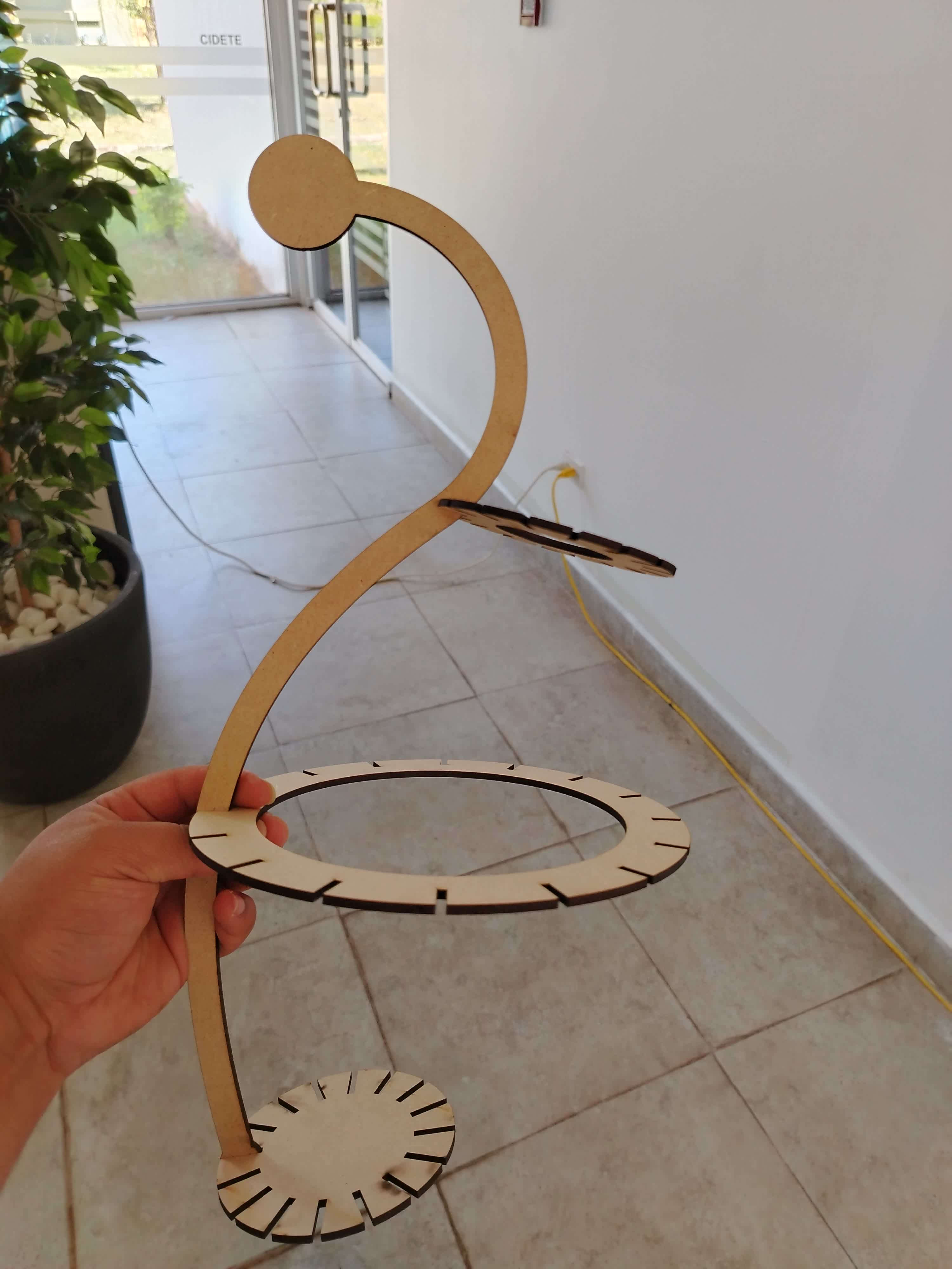
My first laser-cut pieces
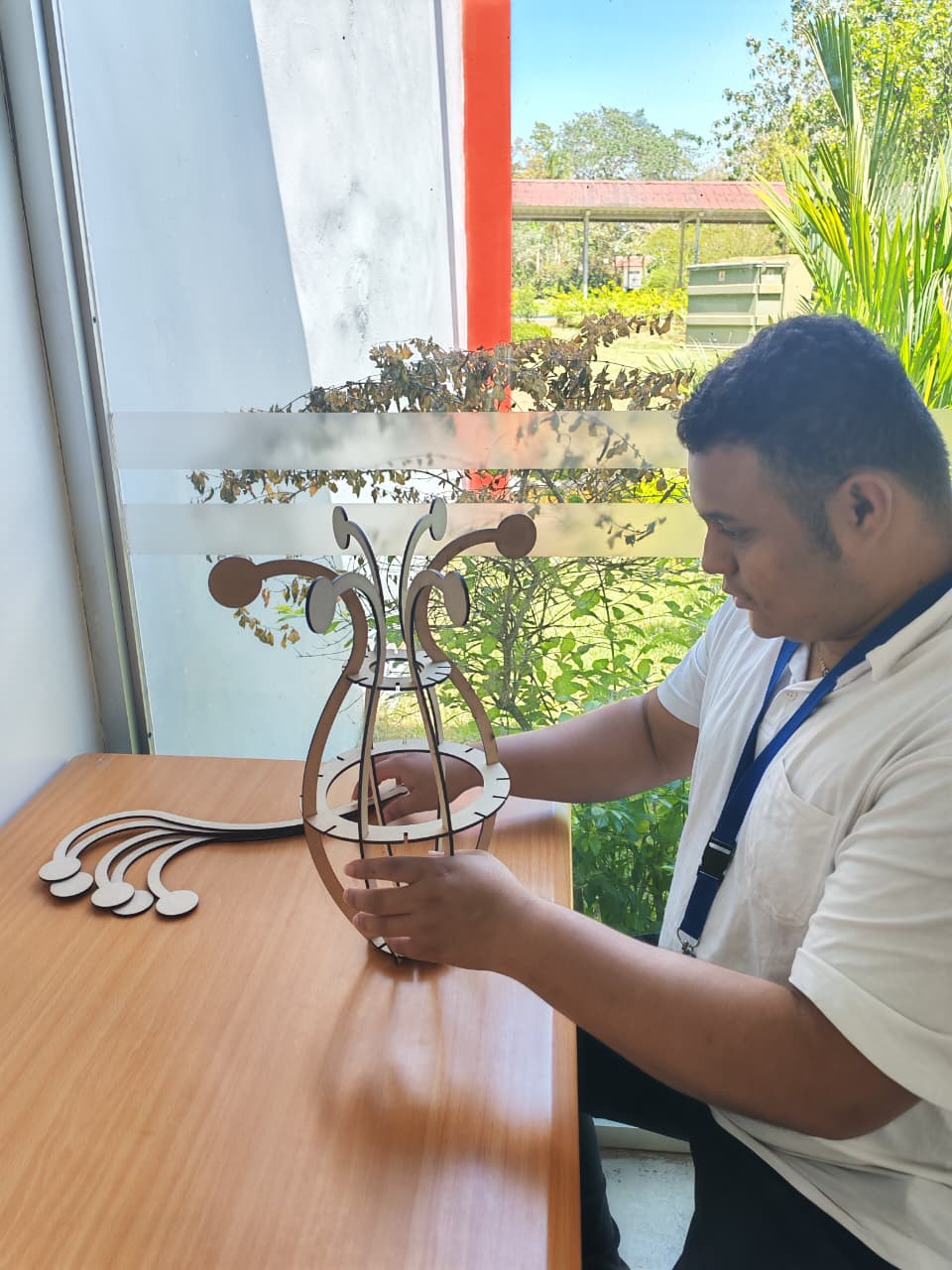
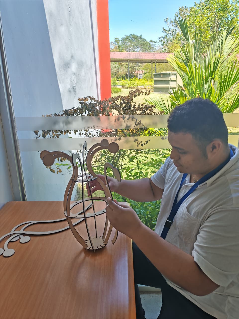
Asamble process
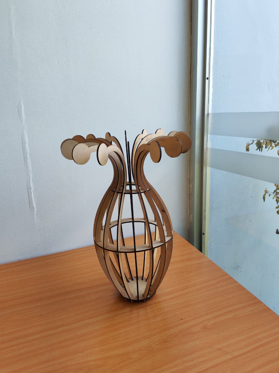
Final Result
The final design is fully parametric, optimized for laser cutting, and assembled using press-fit joints without adhesives.
At the beginning of the design process, the project was intended to have a dual functionality, serving both as a planter and a lamp. However, during development, the decision was made to keep only the planter function, as incorporating a lighting system would have required the design and fabrication of additional components, and the available time was not sufficient to complete this stage.
Nevertheless, the final result faithfully represents the original idea: a concept that originated as an abstract idea and was later materialized through digital fabrication processes. This experience highlighted the potential of these tools to transform ideas into physical objects and reinforced how exciting and empowering digital fabrication can be.
Final Result


Vinil Cut
Dising 2D
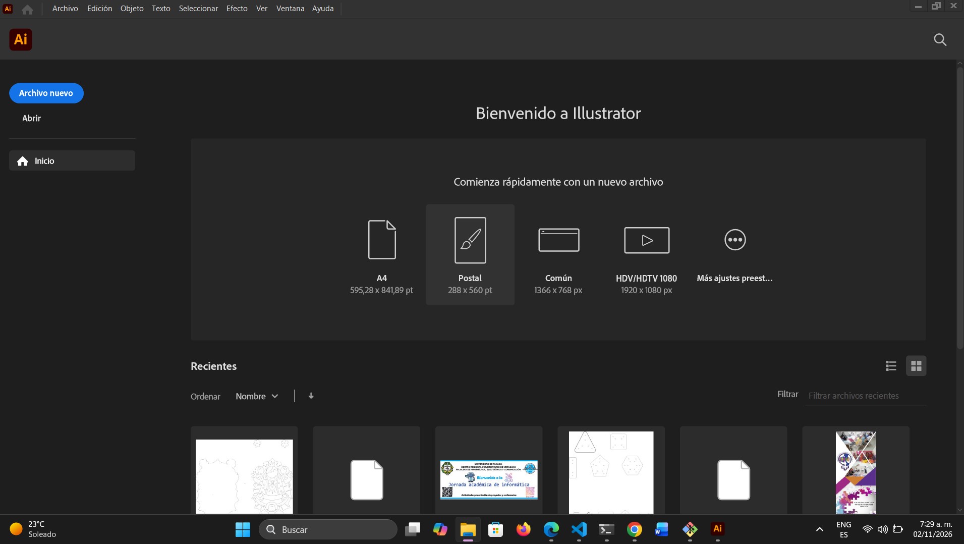
- We opened Adobe Illustrator to design and prepare the file for the cutting process.
- Once the program is open, the main screen is displayed. Here, we locate the “New File” button to start the design.
home screen
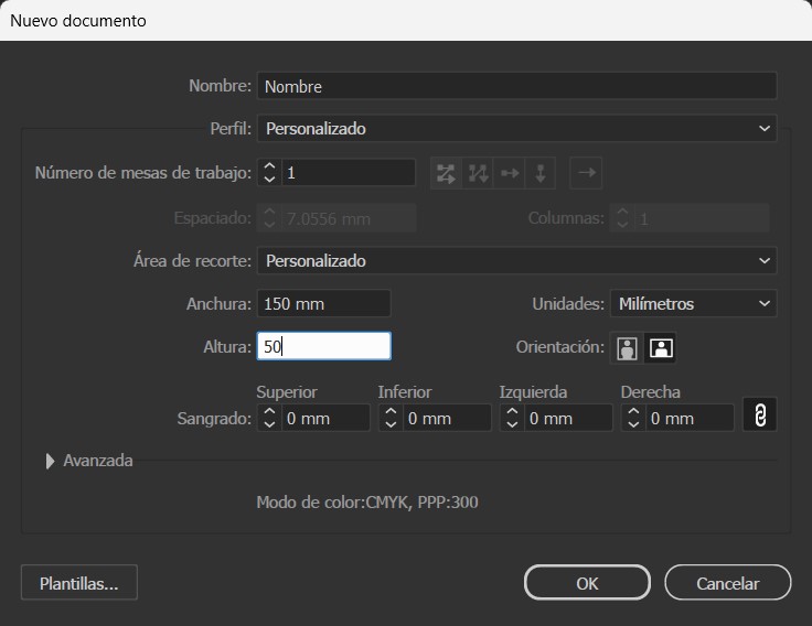
- When we click on the “New File” button, a configuration screen is displayed.
- On this screen, we can configure different parameters such as the document name and the unit of measurement (for example: inches, centimeters, or millimeters). In my case, I will work in millimeters, as it allows for greater precision and the design is not large enough to require larger units.
- Another parameter that can be configured is the size of the artboard used for the design. In my situation, I decided to use a size of 150 mm × 50 mm, since my design will not exceed those dimensions.
- Additionally, in this window we can also modify the orientation of the artboard; in my case, I will keep it in horizontal orientation.
- Once the artboard is configured, we confirm the settings by clicking the “OK” button.
new documents
-
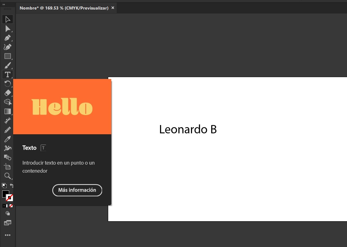
After confirming the configuration, the artboard is displayed. In this workspace, we will design the file for the cutting process; in this case, it is my name, which I will place on my daily-use mug.
-
Using the text tool, we create a text box where I will write my name.
-
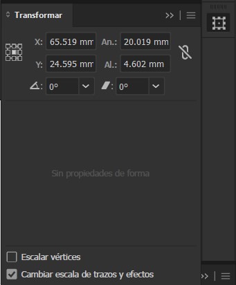
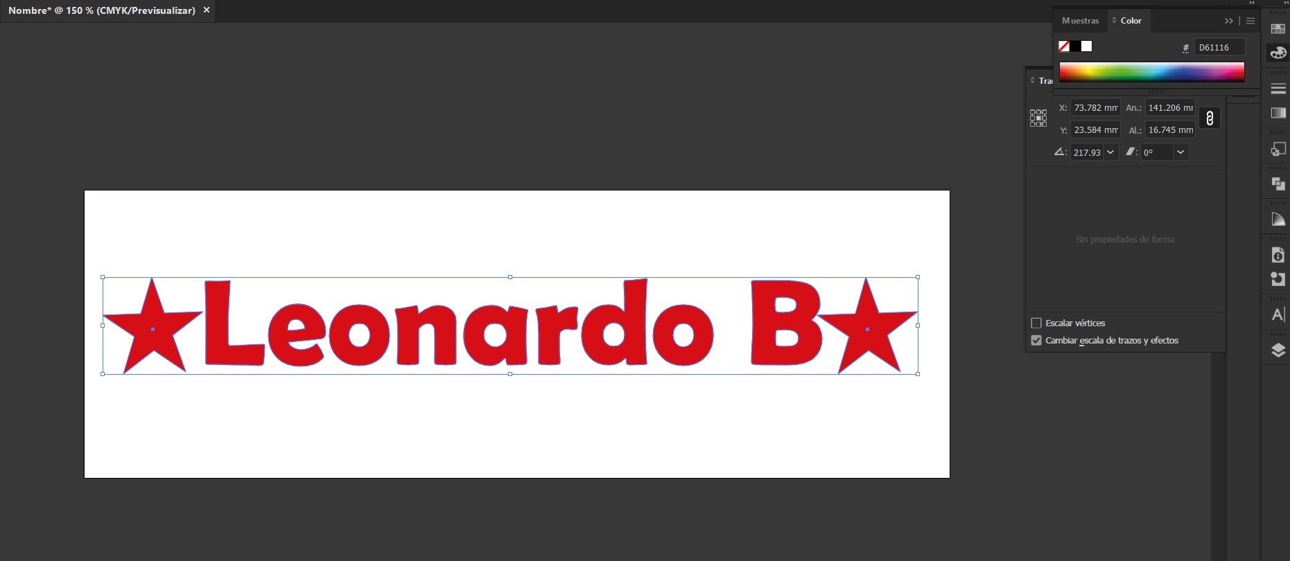
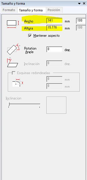
Using the transform tool, we modified the dimensions of the text, taking into account the previously established artboard dimensions. In my case, I set the text width to 100 mm and allowed the height to adjust proportionally to the width.
It is important to note that the dimensions shown in the image do not correspond to those used in the final design; those measurements correspond to the initial size of the text before it was adjusted.
-
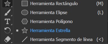
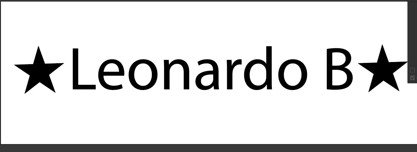
Using the shape tool, we added stars on both sides of the text so that it has the following appearance:
-
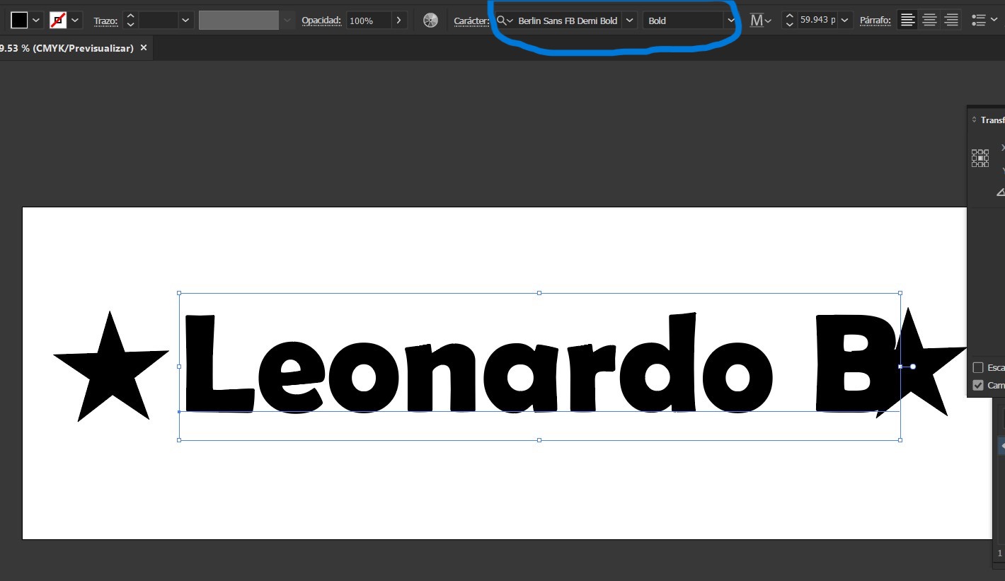
We changed the text font to Berlin Sans FB Demi Bold . I chose this font because I liked its appearance.
Then, we adjusted the text together with the stars and applied a red color, resulting in the final design as shown below:
-
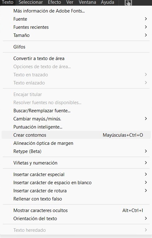
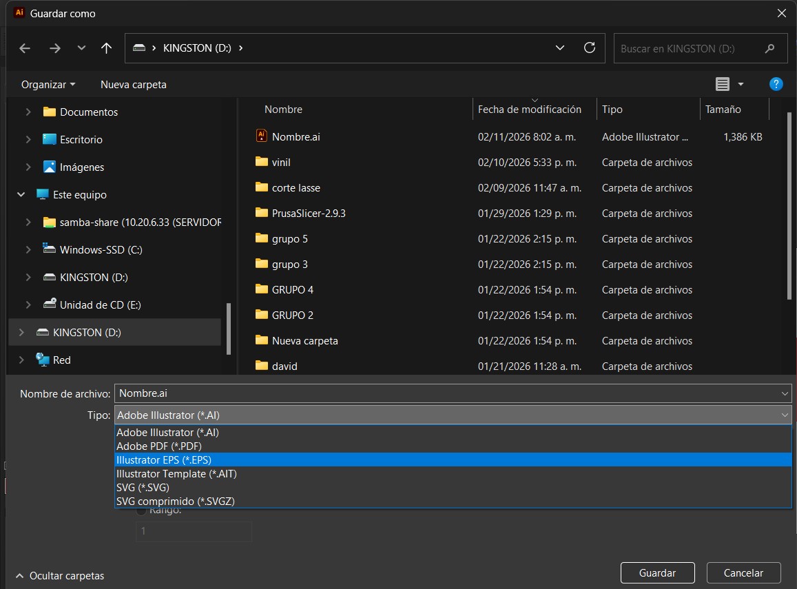
We save the file in EPS 2008 format; however, before doing so, it is necessary to convert the text into outlines so that the cutting plotter software can recognize it as cutting paths. To do this, we go to the menu bar, select the “Text” option, and click on “Create Outlines”.
- Once the file has been saved in EPS format, we proceed with the vinyl cutting process.
Subsequently, we save the file in EPS format.
Vinyl cutting process using the CAMM-1 GS-24 cutting plotter
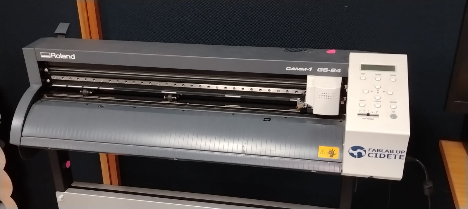
Machine type: Desktop / tabletop vinyl cutter.
Material loading width: 50 mm to 700 mm.
Maximum cutting area: Up to 584 mm in width and 25,000 mm in length (continuous cutting).
Cutting speed: Between 10 and 500 mm/s.
Adjustable cutting force: from 30 to 350 gf (grams-force).
Here you can find more information about the Roland CAMM-1 GS-24 , including its specifications, features, and common uses, as well as official documentation, application examples, and technical support on the manufacturer’s website.
-
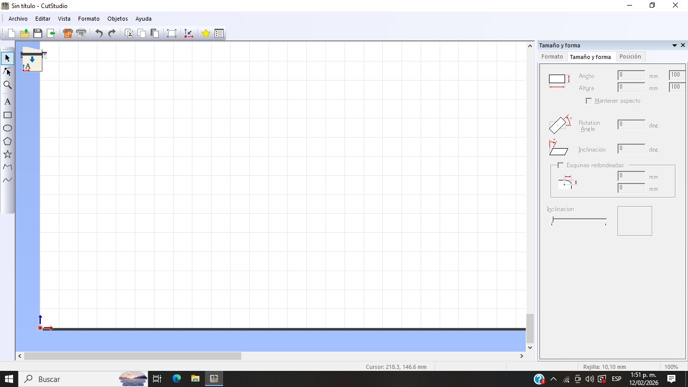
To begin the cutting process, the first step was to launch the CutStudio software, which is the program used by the CAMM-1 GS-24 cutter and allows us to send our design to the cutting plotter. Once the program is open, the main interface is displayed, as shown in the following image.
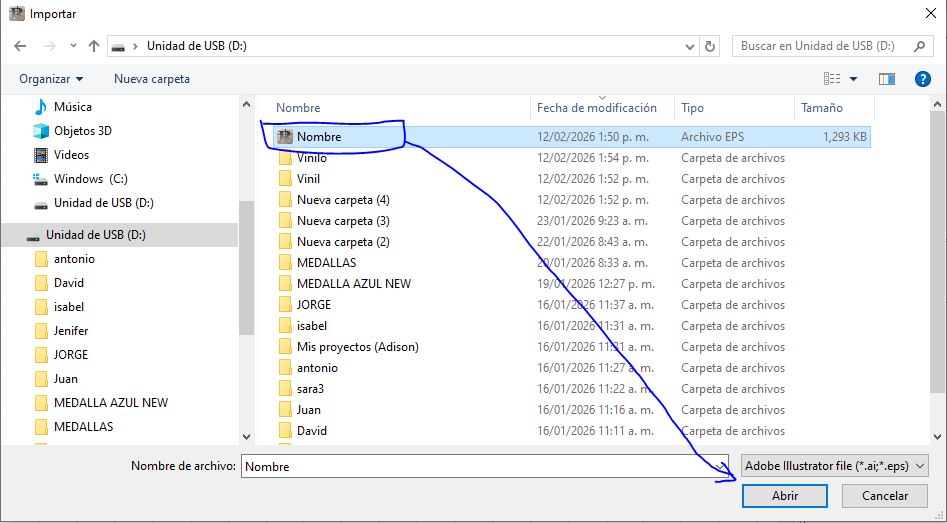
The next step is to load our design for the cutting process. To do this, we go to the top menu, select the File section, and choose the Import File option. A file explorer window then opens, where we navigate to locate our EPS file; we select it and confirm the action to load it into the software.
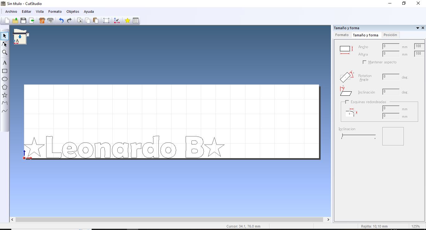
Loaded File
-
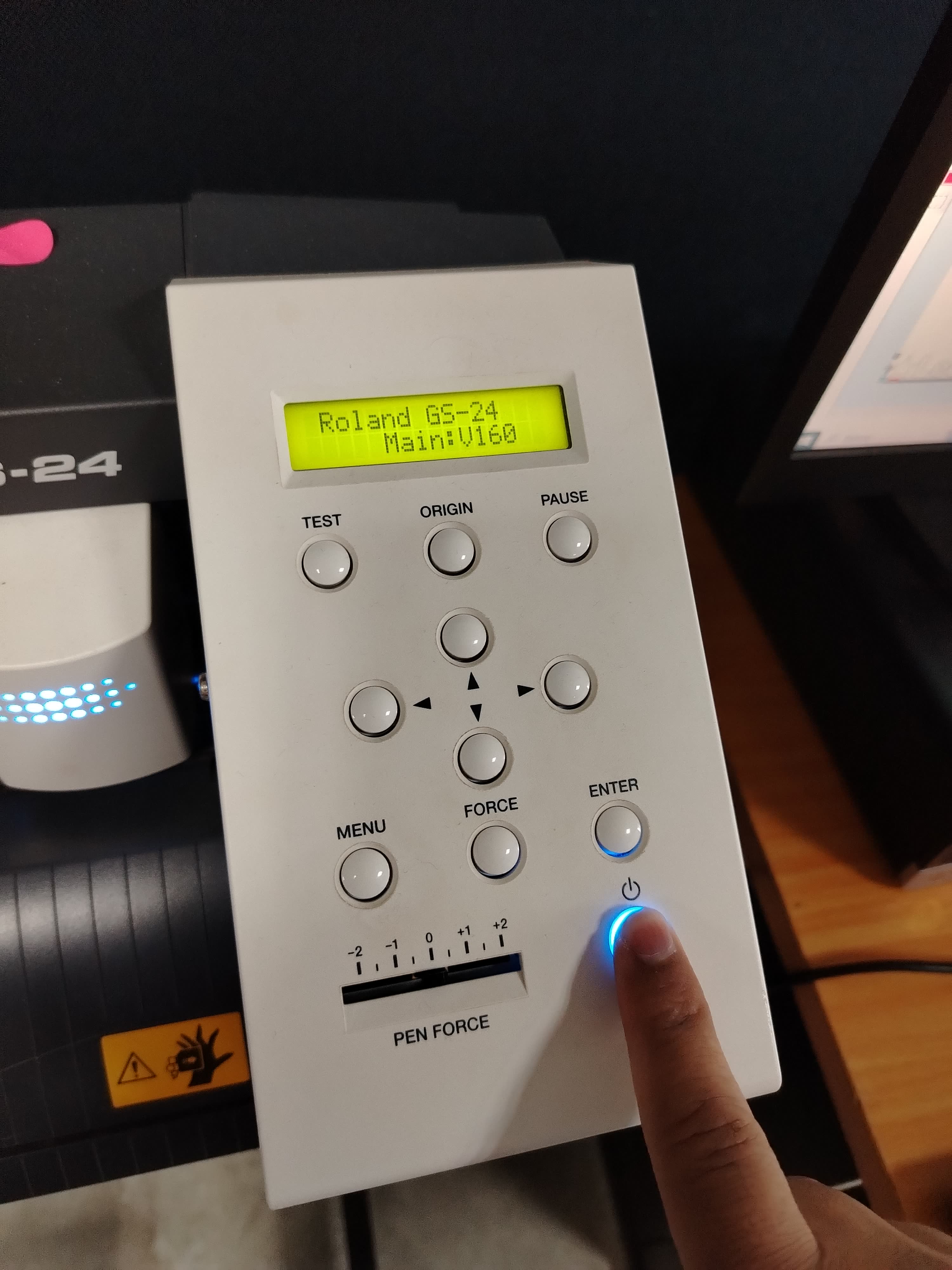
Once the file was loaded into the software, I turned on the cutting plotter.
At this point, I proceeded to select the material I would use; in this case, I chose red adhesive vinyl.
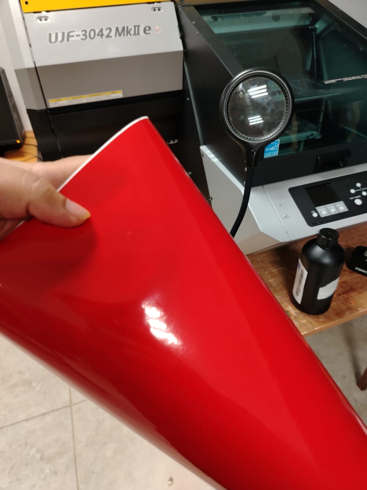
Next, I loaded the material into the cutting plotter.
material loaded
Subsequently, I set the cutting speed to 10 cm/s, which determines how fast the cutting head moves during the cutting process. Next, I adjusted the cutting force to 80 gf, a parameter that defines the amount of pressure the blade applies to the material in order to achieve a proper cut.
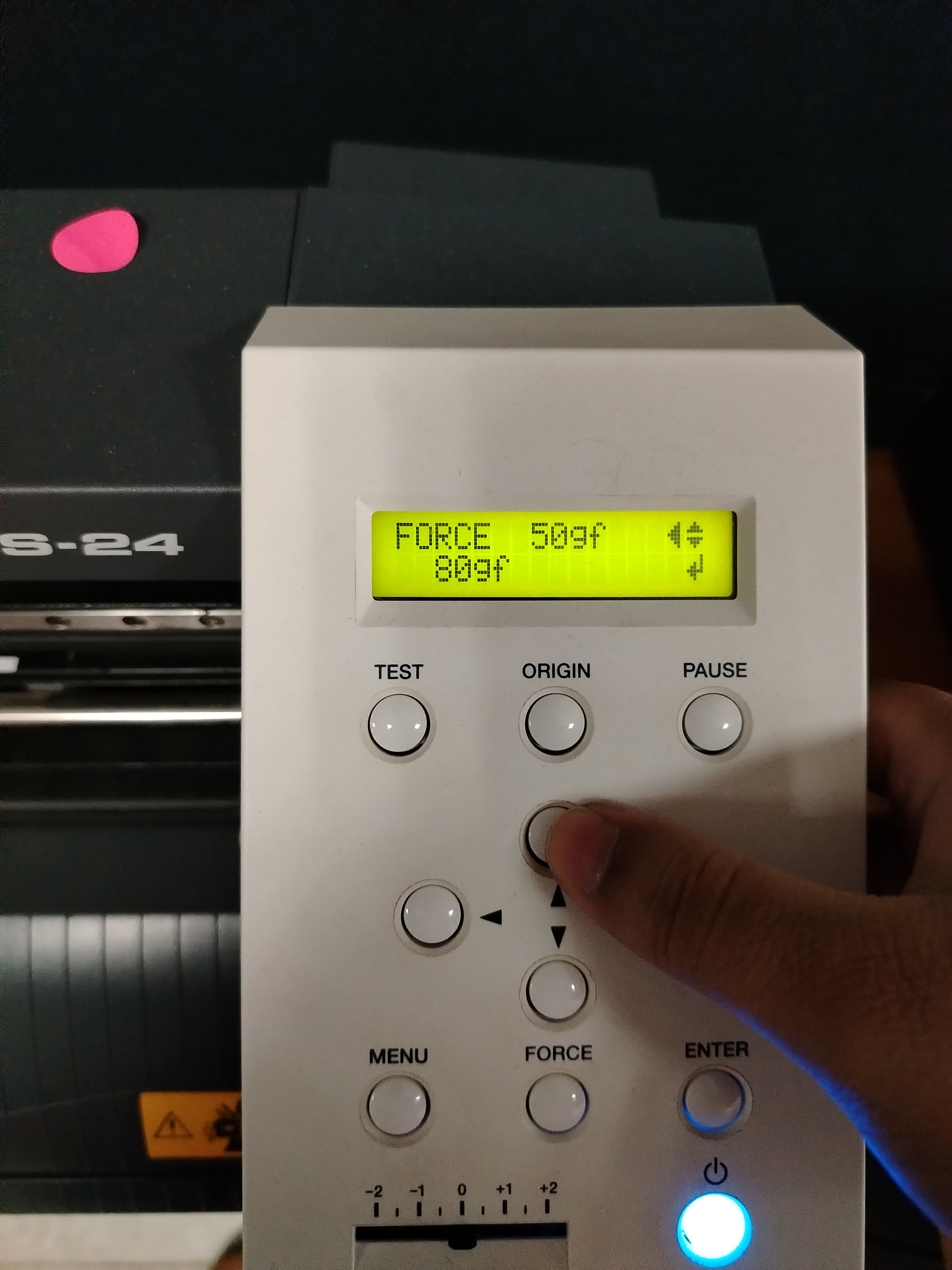
Speed cut
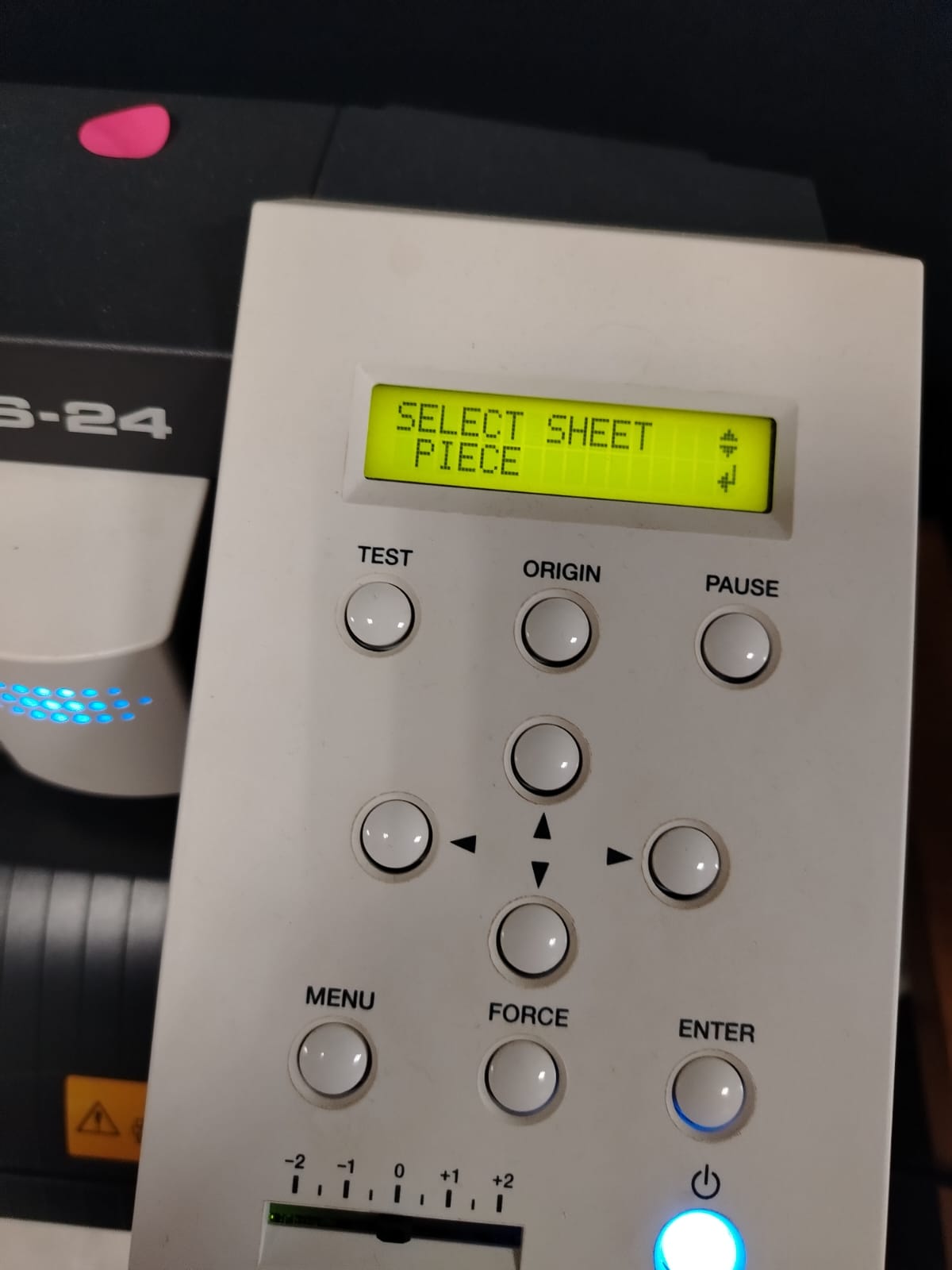
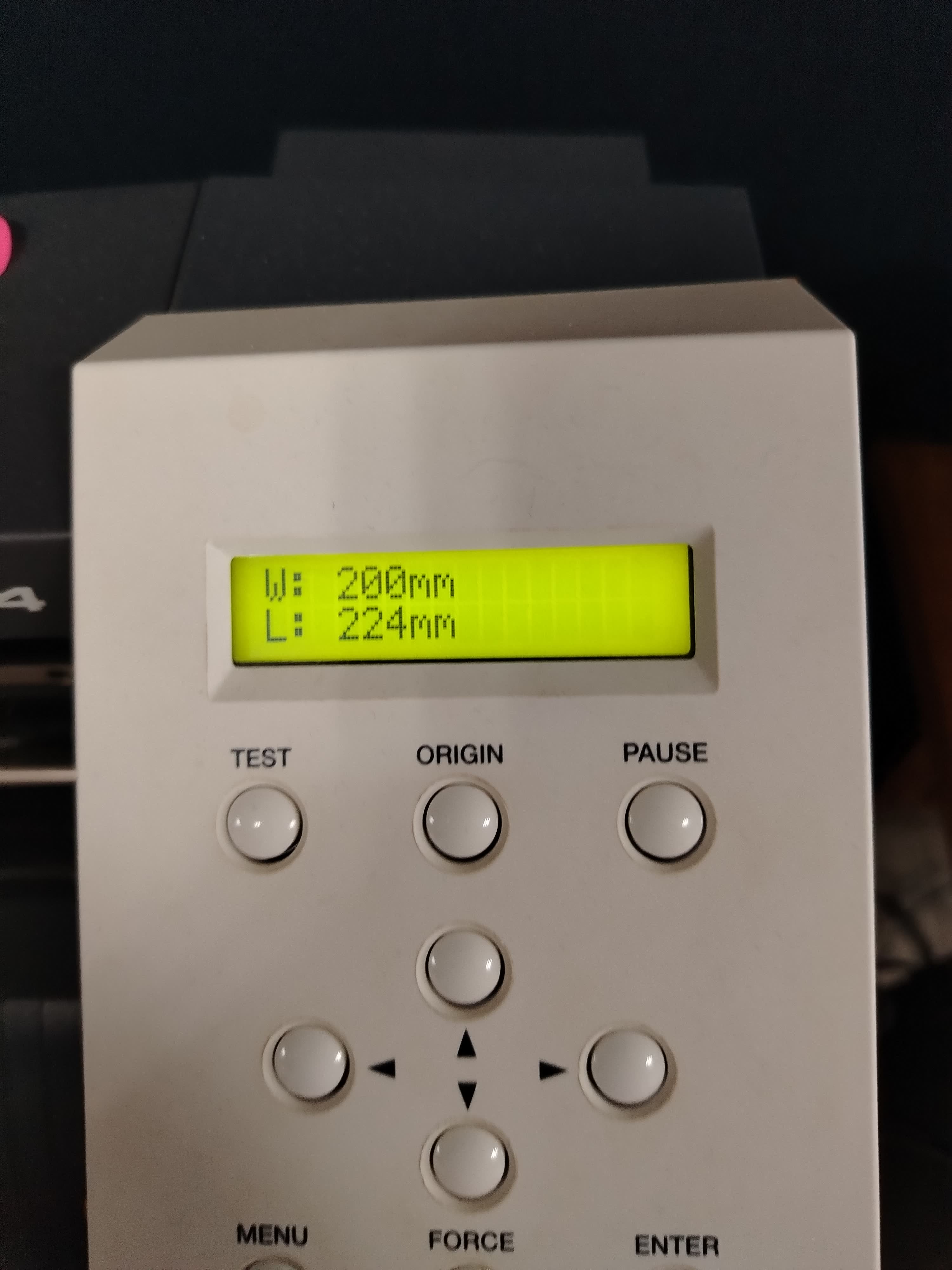
Once the cutting force and speed were configured on the machine, I selected the sheet type. The plotter has two cutting modes: Piece mode and Roll mode. In my case, since I was only cutting a single name, I chose Piece mode. When this mode is selected, the machine automatically measures the loaded material. It is important that the dimensions detected by the plotter are larger than the dimensions of the design to ensure proper cutting. To verify this, we compare the material measurements captured by the plotter with the design dimensions displayed in the CutStudio software.
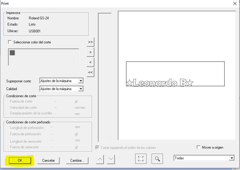
Once it was verified that the machine was properly configured, the material was loaded, and the design was ready, I proceeded to send the file for cutting. To do this, I went to the top menu of the CutStudio software and selected the Cut button. Observe the following image.

Subsequently, a window will appear where we will confirm the cutting action.
Once the action is confirmed, the machine will begin the cutting process. Observe the following video.
cutting
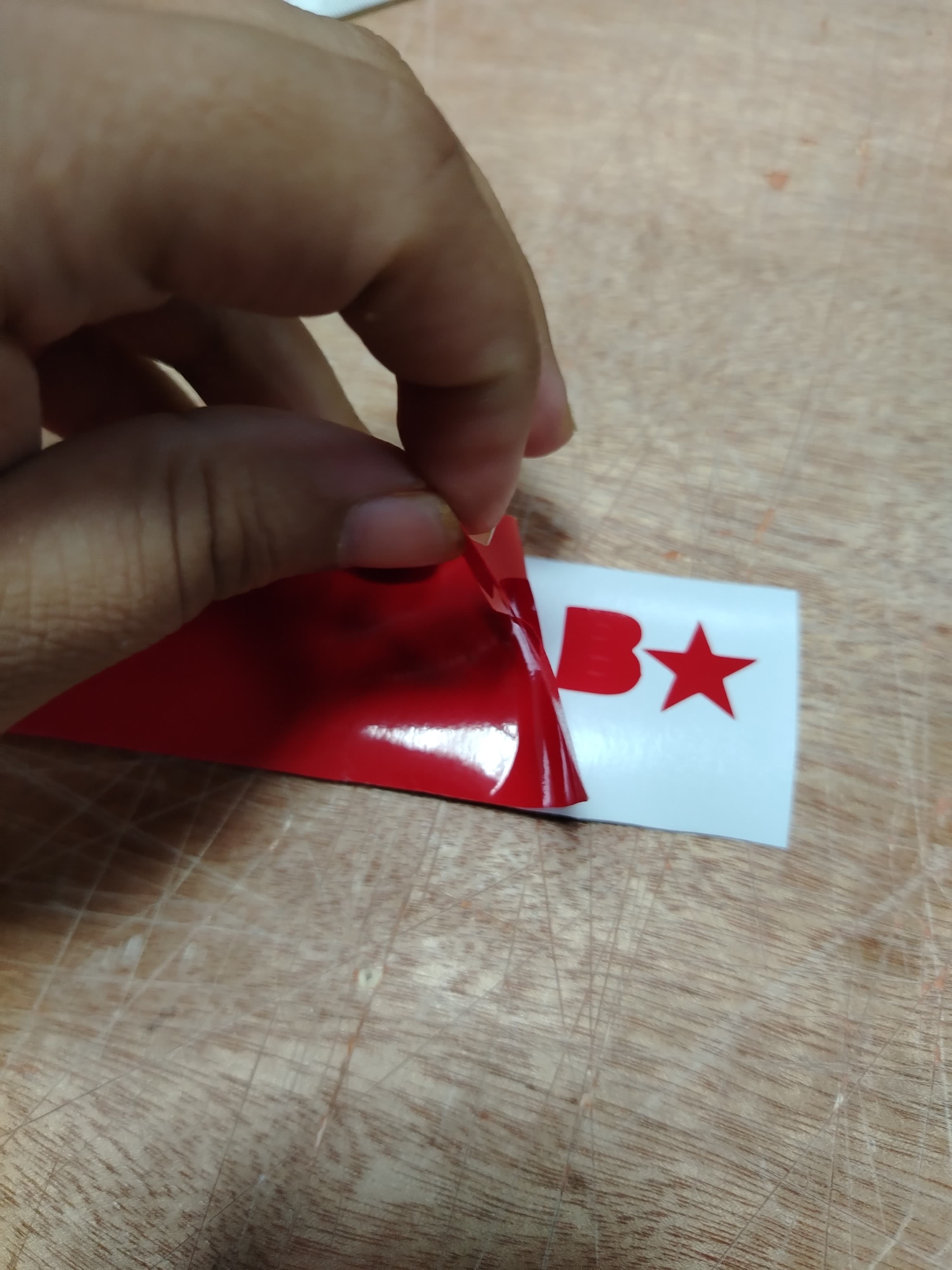
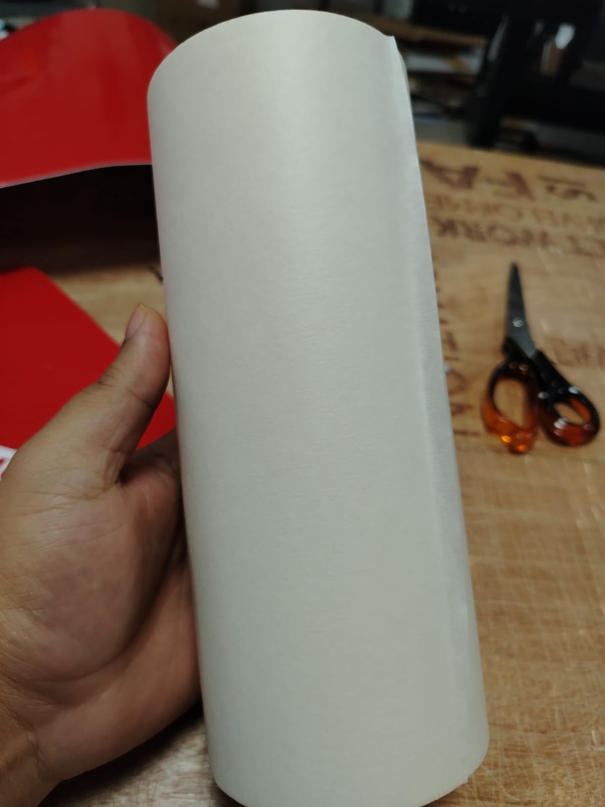
Once the cutting process was completed, I proceeded to weed the cut design.
For the installation of the design, I used transfer paper, which allows the vinyl to be lifted and positioned accurately, facilitating its correct application on the final surface.
transfer paper
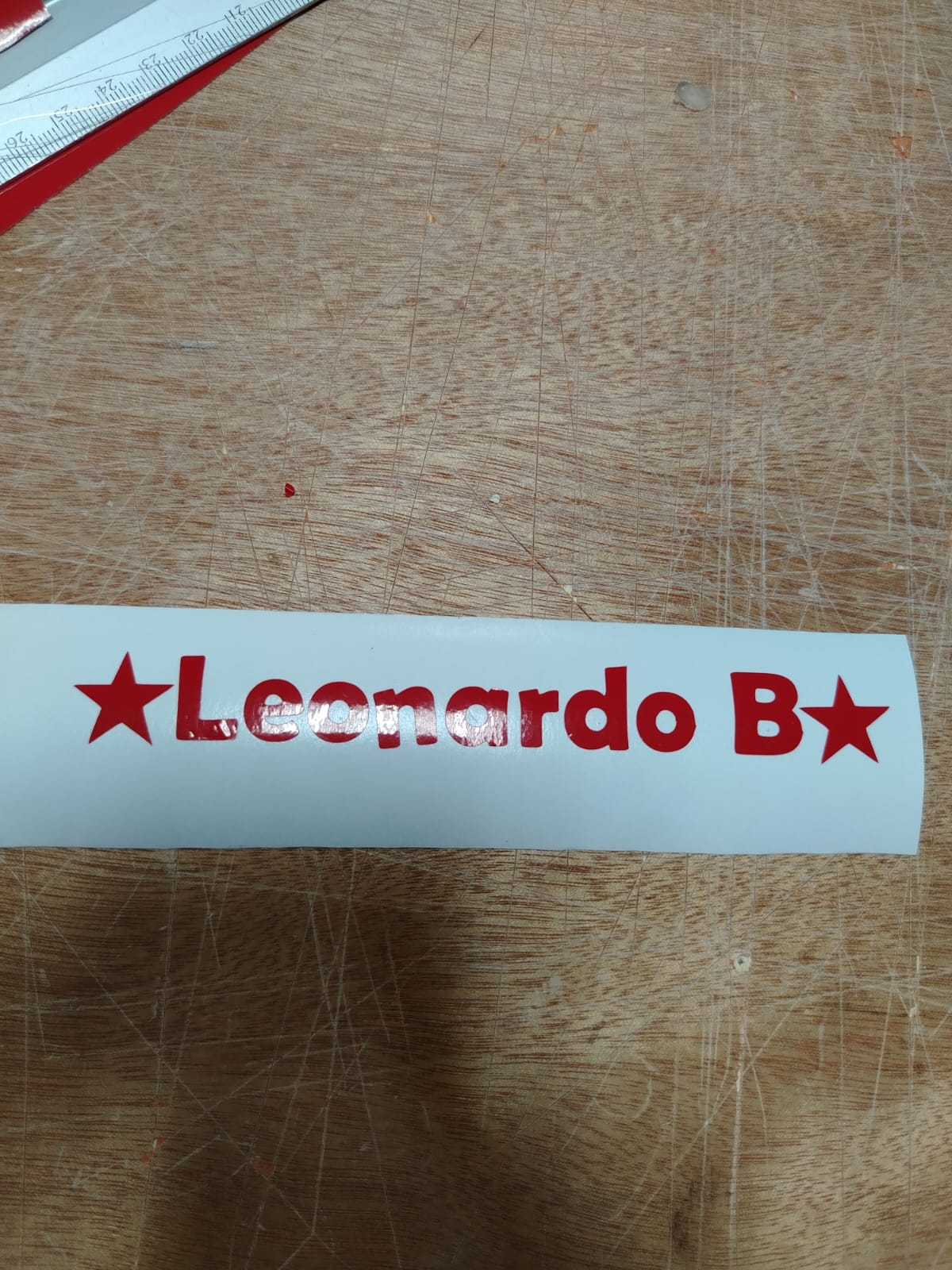
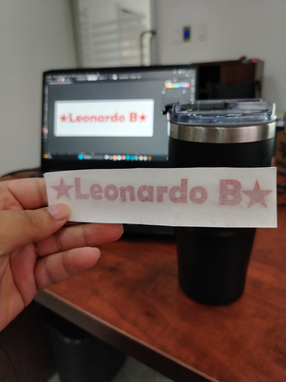
To do this, we covered the design with transfer paper using a plastic squeegee, applying even pressure to ensure proper adhesion of the vinyl to the transfer.
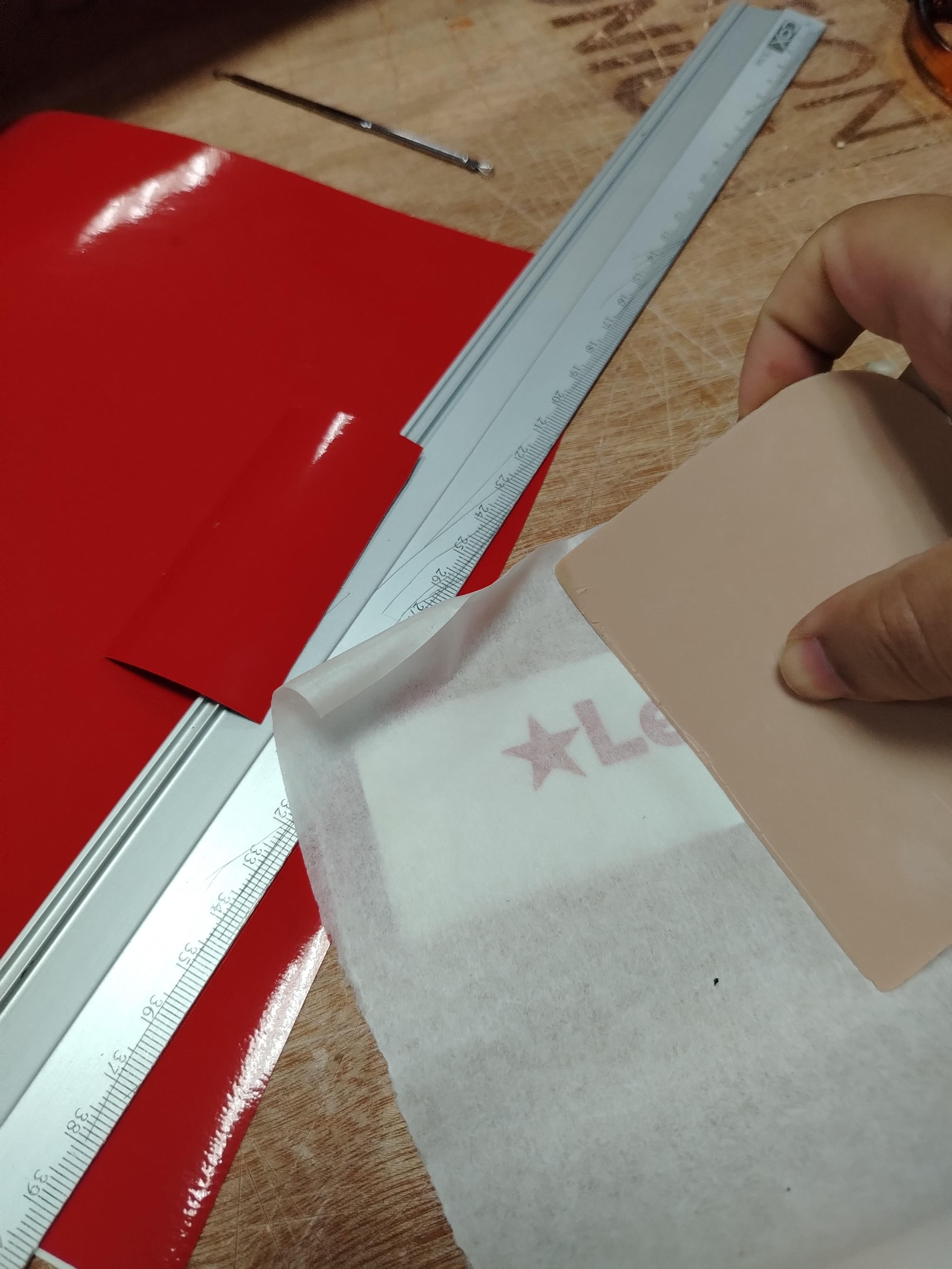
The result should look as shown in the following image.
As the final step, I applied the design onto the final surface; in this case, my cup.
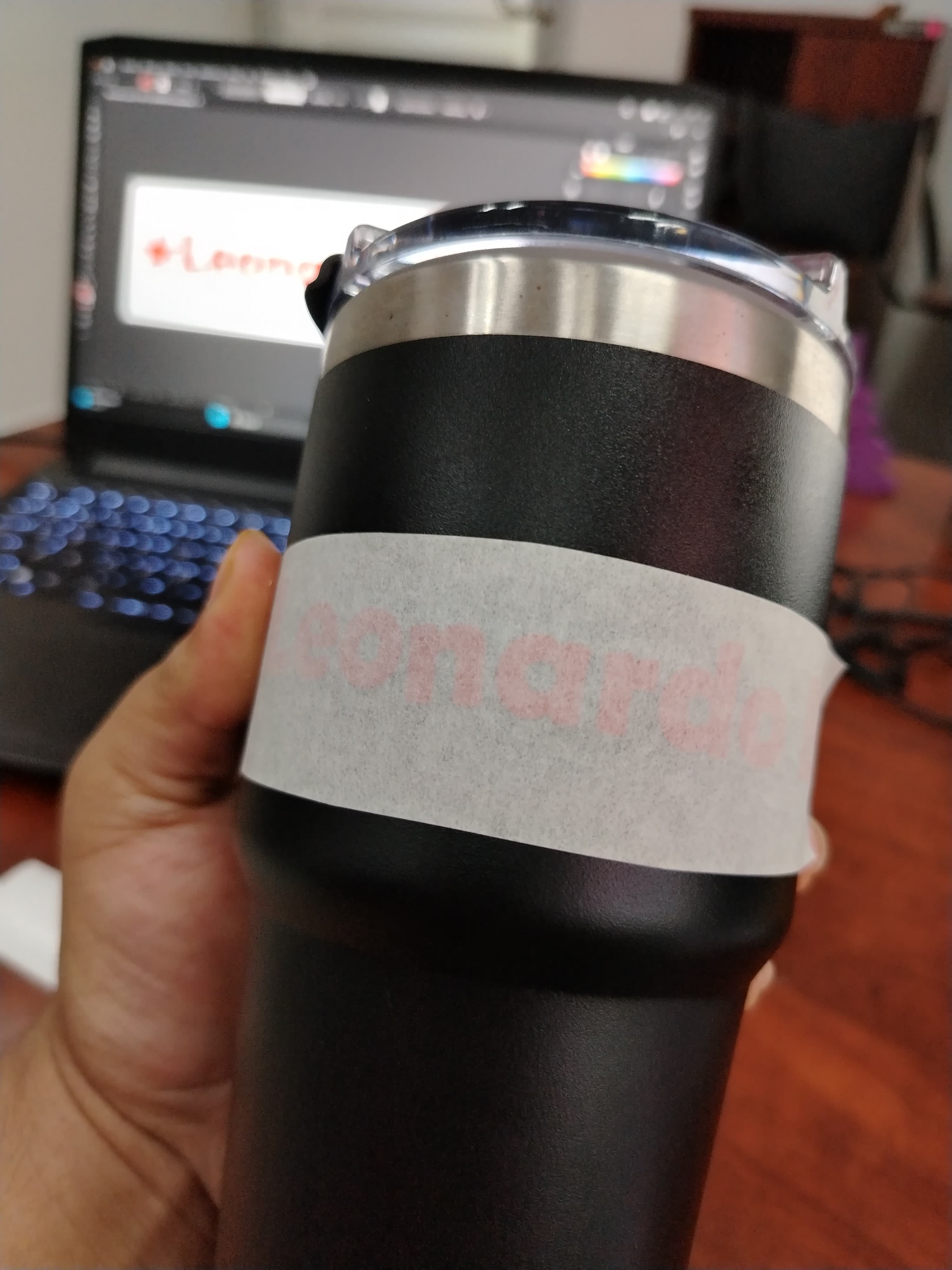
Result Final
During this week, I learned about parametric design and understood that kerf is a very important factor when manufacturing assembly kits. I also learned about vinyl cutting and discovered that there are different types of materials, such as textile vinyl, which allows customization of garments like sweatshirts. Most importantly, I learned that using cutting equipment such as laser cutters and vinyl cutting plotters allows us to save many hours of manual work while significantly improving precision and efficiency in the manufacturing process.
Laser cutting machines, such as the FX CMA-1309, are safe to use when operated correctly; however, it is essential to strictly follow safety guidelines to protect both the user’s physical integrity and the equipment itself.
During operation, the machine door must not be opened while cutting or engraving is in progress. Some machines are equipped with safety sensors that prevent operation when the door is open, reducing risks and helping to avoid accidents.
It is also crucial to verify the materials before cutting. Some materials may be flammable or reflective; for example, cardboard can catch fire if the laser speed and power are not properly configured. Additionally, materials such as PVC must not be used, as they release toxic gases that are harmful to human health.
During any cutting or engraving process, both the fume extraction system and the air compressor must be turned on. Without these systems, smoke can accumulate and stain or damage the mirrors and lens, directly affecting cut quality and reducing the machine’s lifespan.
Finally, it is important to maintain an adequate level of distilled water in the chiller and replace it periodically, preferably every two weeks, depending on the frequency of use. Proper preventive maintenance ensures optimal and safe operation and extends the lifespan of the laser cutting system.
Dowload File
Mission accomplished! :-)