Group assignment
Objective
-
probe an input device's analog levels and digital signals
Here I share the link to my group assignment.
Indivual assignment
- measure something: add a sensor to a microcontroller board that you have designed and read it
What I know
I have worked with sensors such as the DHT11 and soil moisture sensors, but always using Arduino boards. I have never used a sensor like the flex sensor that I will be working with this week.
For my final project, I will use a flex sensor, which changes its resistance depending on its angle or how much it is bent. Therefore, this week I decided to perform some tests with this sensor.
I obtained a commercial flex sensor from an electronics store here in Panama. Additionally, I got velostat material and conductive thread to build my own flex sensor and evaluate whether it is feasible to make one myself or use the commercial version.
To build a flex sensor, I used the following materials:
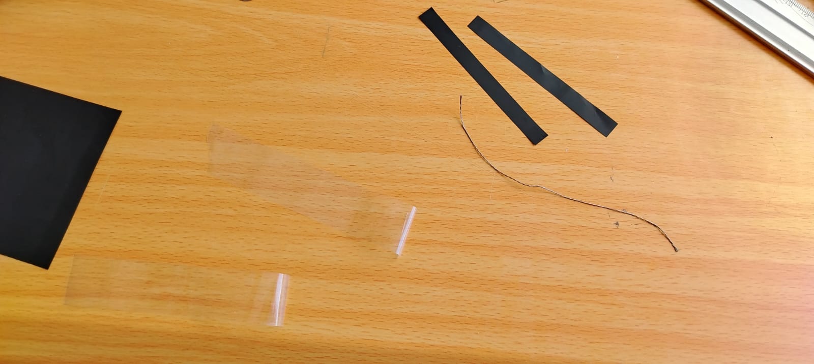
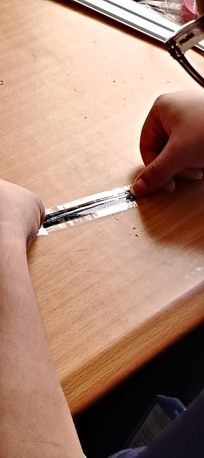
I built it as follows:
-
I took adhesive tape, cut a 2.5-inch piece, and divided it into two strips, as shown in the previous image.
-
The next step was to cut two pieces of conductive thread, each 3 inches long.
-
Then, I cut three strips of velostat measuring 1 cm by 2.2 inches.
-
I placed a piece of conductive thread on the previously cut adhesive tape. See the image below:
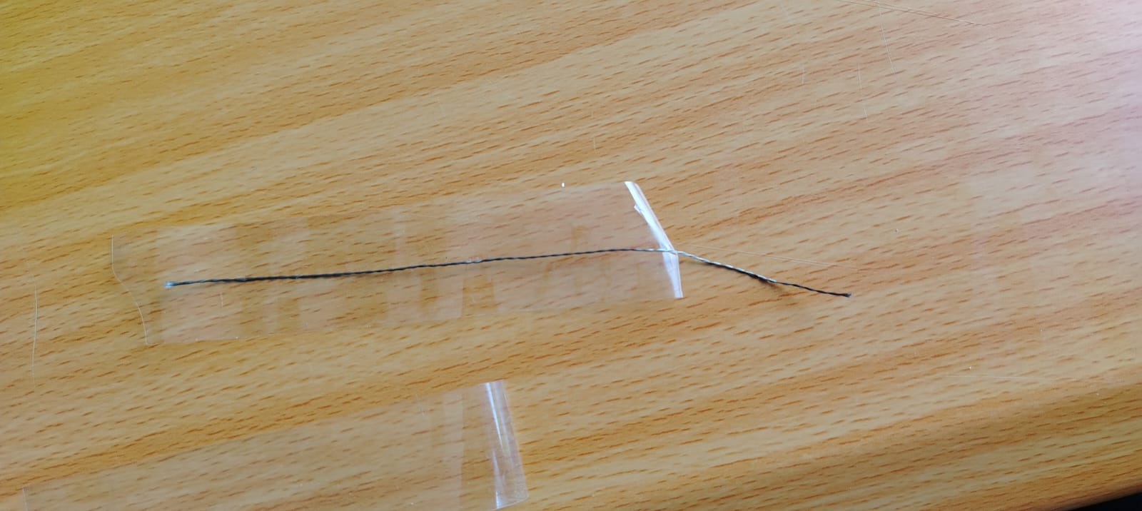
-
After placing it, I took two velostat strips and placed them on top of the conductive thread and adhesive tape, as shown below:
-
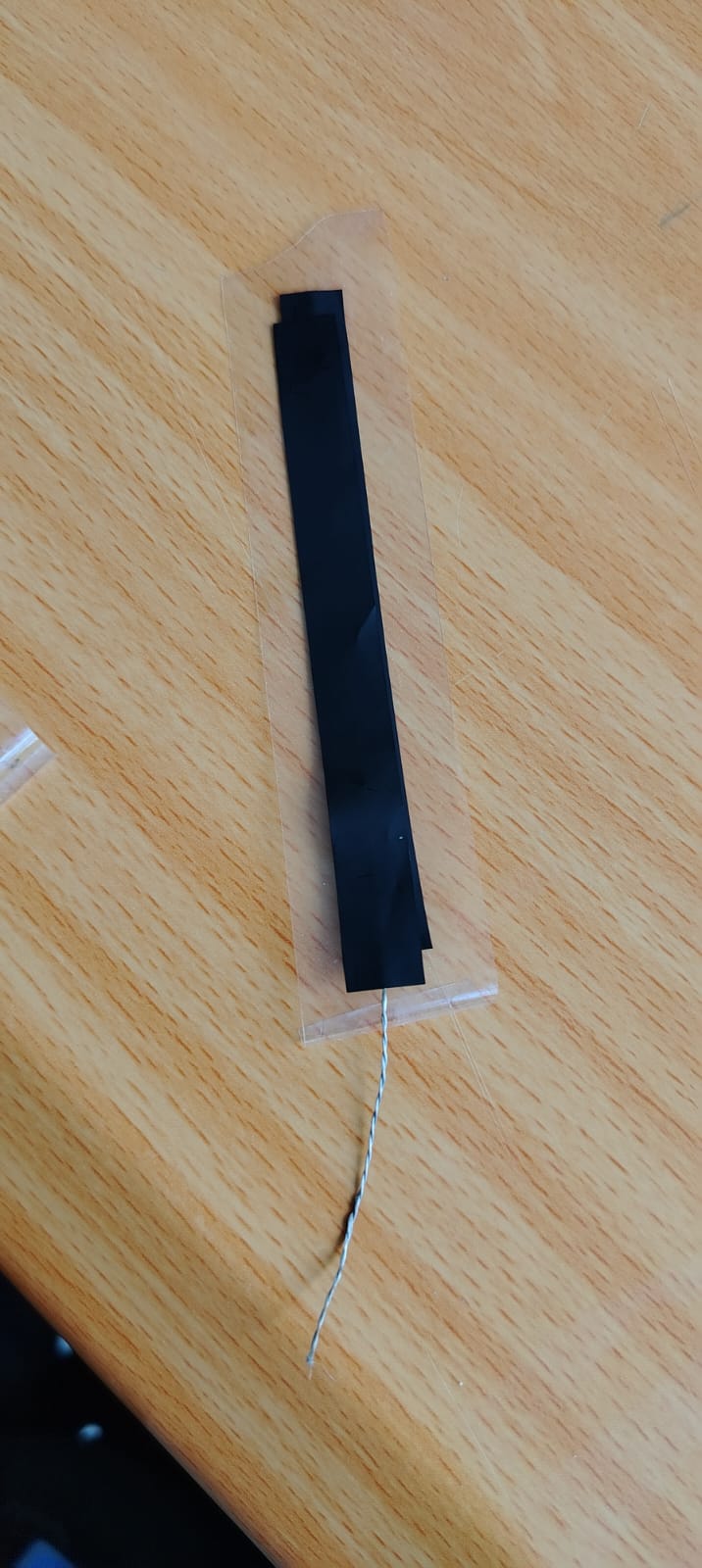
The next step was to repeat the process with another piece of adhesive tape, velostat, and conductive thread. I placed the conductive thread over the tape and then added a strip of velostat, creating two identical parts that were later combined in a “sandwich” structure.
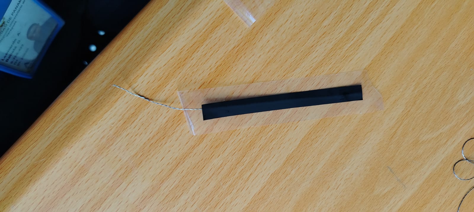
DIY Flex Sensor
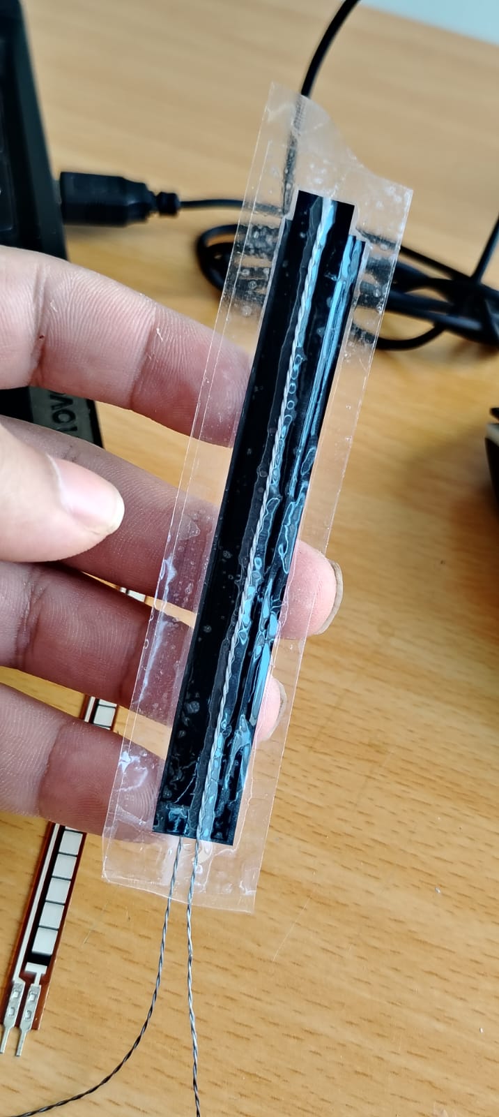
After finishing my flex sensor, I proceeded to take measurements using a multimeter, testing both the handmade sensor and the commercial one.
The handmade flex sensor showed a resistance of approximately 160 ohms at rest; however, when bent, the readings were not stable.
Next, I measured the resistance of the commercial flex sensor. I obtained values of approximately 18k ohms at rest, and when bent, it decreased to around 9k ohms. The readings were much more stable compared to the handmade sensor.

At this point, I decided to use the commercial flex sensor, as it provides better stability.
To start using my flex sensor, I decided to use the board I built in Week 8.
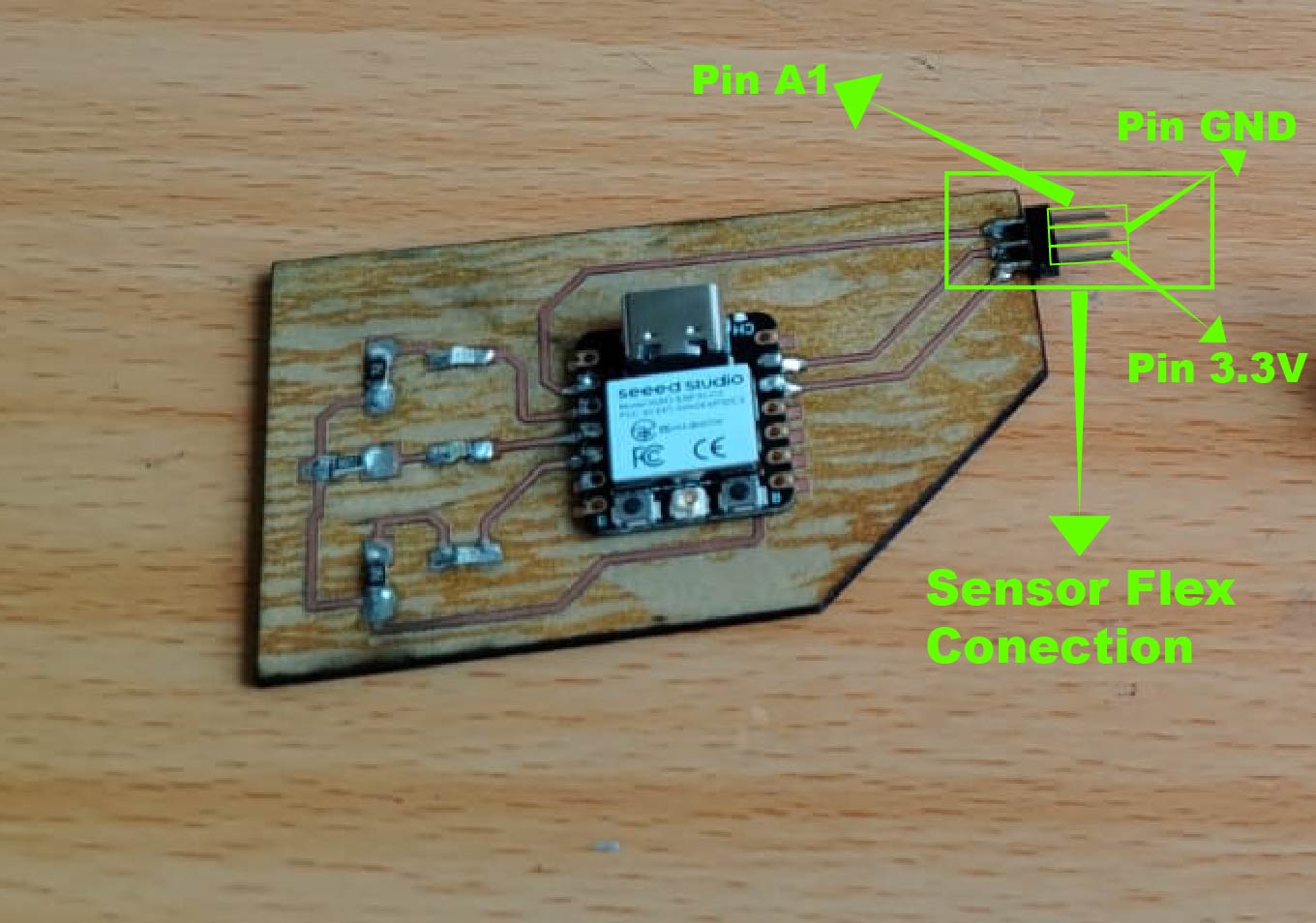
To connect a flex sensor to a microcontroller, a voltage divider must be implemented, according to the datasheet. The recommended fixed resistor is 25k ohms; however, based on my measurements, the sensor shows approximately 18k ohms at rest and around 9k ohms when bent. Therefore, to determine the appropriate resistor value, I used the formula provided in the following datasheet.
📐 Voltage Divider
- R1 << Sensor → Low voltage, small range
- R1 >> Sensor → High voltage, small range
- R1 ≈ Sensor → Maximum and centered range
Vout = Vin × R2 / (R1 + R2)
Where:
Vin = Input voltage
R1 = Fixed resistor
R2 = Variable resistor (sensor)
Vout = Output voltage
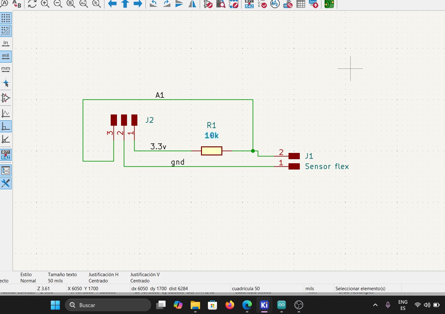
Additionally, the datasheet recommends using a 10k ohm fixed resistor, which I implemented in my circuit to ensure proper operation of the voltage divider.
Vout = 3.3V × 9 / (10 + 9)
Vout = 29.7 / 19
VoutMIN = 1.56V
ADC ~ (1.56/3.3)*4095
ADC min ~ 1935
Vout = 3.3V × 18 / (10 + 18)
Vout = 59.4 / 28
VoutMAX = 2.12V
ADC ~ (2.12/3.3)*4095
ADC max ~ 2630
These are approximate values that we should expect when connecting the sensor.
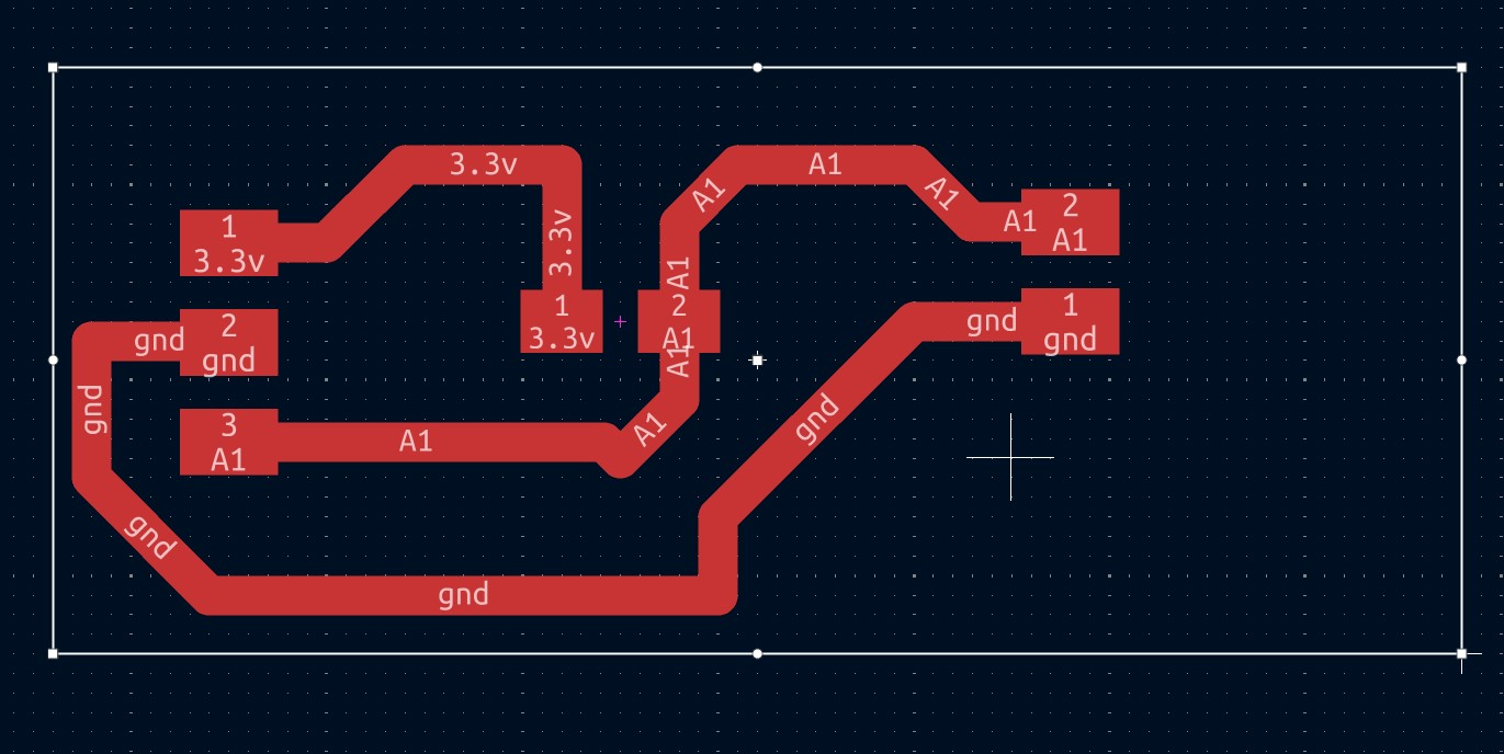
Once I understood this, I proceeded to design my PCB and fabricate it as I learned in Week 8.
Diagram
PCB
Result
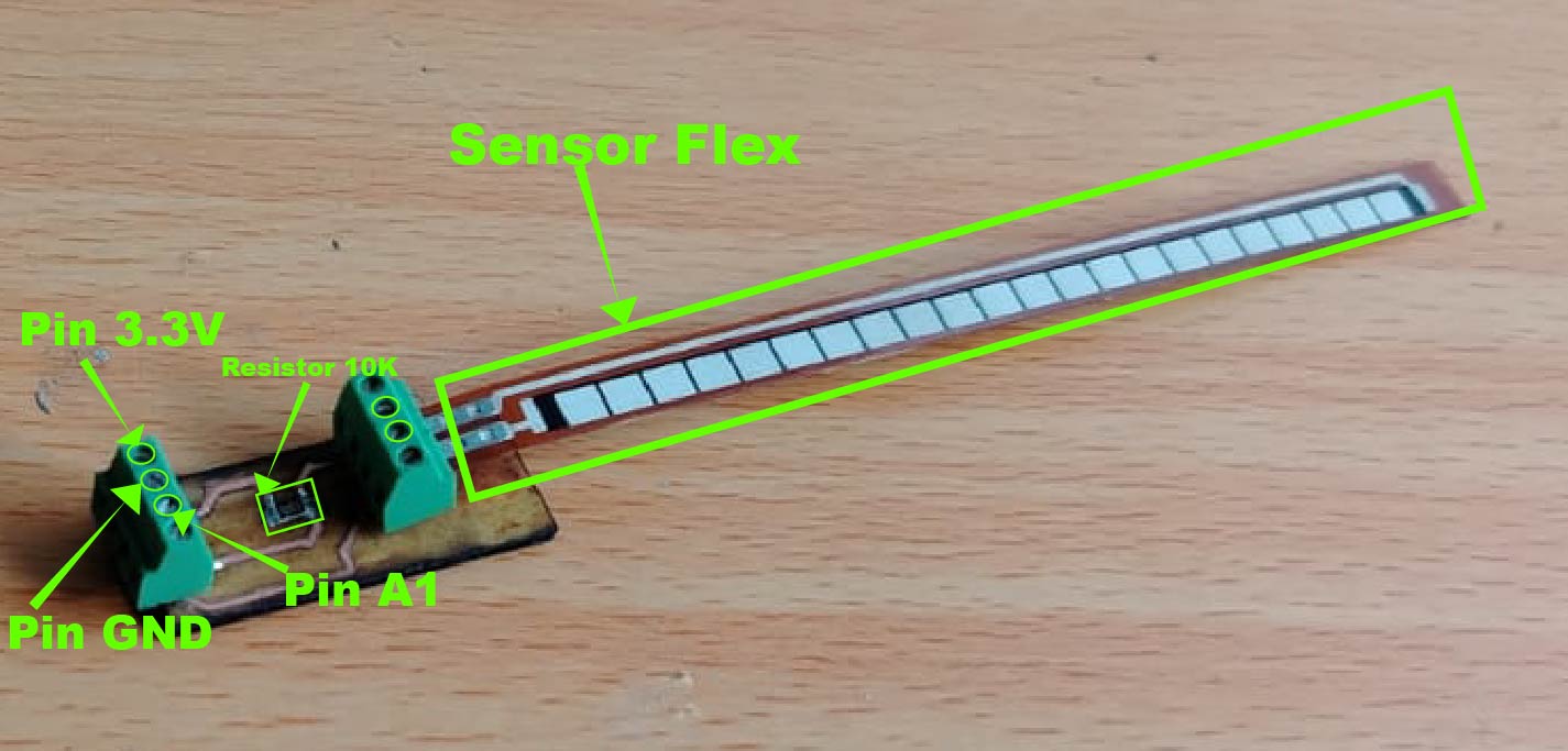
As shown in the previous image, this is how the flex sensor module turned out, ready to be connected to my PCB board fabricated in Week 8.
After building the flex sensor module, I proceeded to connect it to my board.
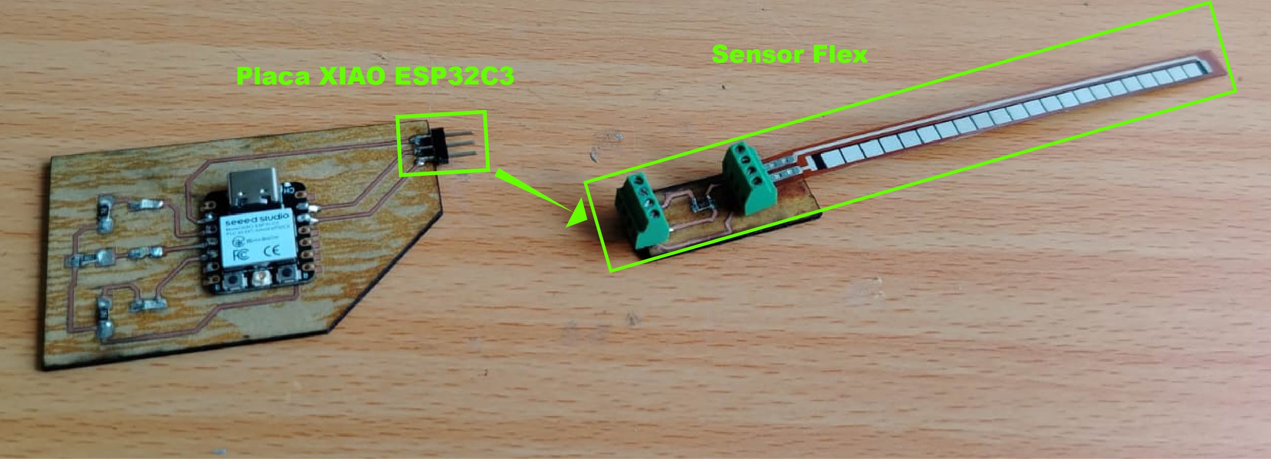
Once connected, it should look like this. I could have used jumper wires in a male-to-female configuration, but I decided to connect it as shown in the following video.
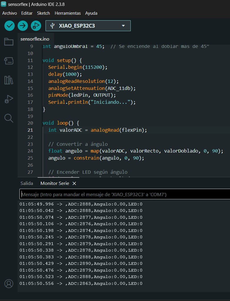
After connecting everything, I proceeded to program the board. The instruction I implemented was to turn on a green LED when the flex sensor angle is greater than 45 degrees. However, before that, I displayed the ADC value.
As you may remember from the previous section where we performed calculations for the voltage divider, we also calculated the expected ADC value. This was done by dividing the output voltage of the divider by the input voltage (Vin = 3.3V provided by the XIAO ESP32C3) and multiplying the result by 4095.
Based on these calculations, we predicted an ADC value of approximately 2630. In the following image, we can observe that the measured value is not exactly the same, but it is very close. The actual value shown in the serial monitor is around 2888 when the flex sensor is at rest (0-degree angle).
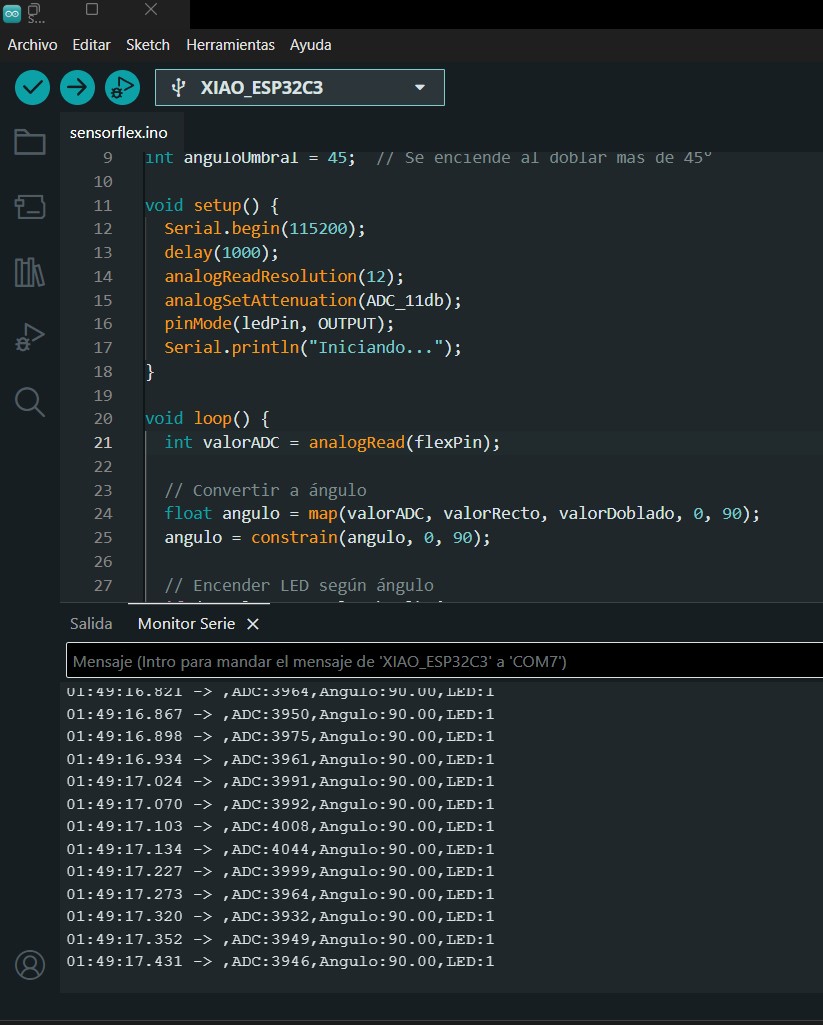
When the sensor is bent, the ADC value increases to approximately 3900. Although these values do not exactly match the theoretical calculations, they are expected to vary in real-world conditions. These values are typically confirmed during testing and sensor readings.
Even so, the results are useful because they provide a minimum and maximum range that can be mapped to angles, allowing us to control outputs such as turning on an LED.
Code Explanation
To verify that our sensor works correctly, we created a program that turns on an LED when the sensor is bent beyond a 45-degree angle.
At the beginning of the program, we declare global variables such as the A1 pin, which is connected to the flex sensor,
and the D3 pin, which is the digital pin connected to the LED. Additionally, we define variables such as
straightValue and bentValue.
These values must be adjusted according to the ADC readings obtained once the sensor is connected. This allows us to map the sensor readings to angles and correctly control the LED behavior.
                                const int flexPin = A1;      // Pin where the flex sensor is connected
                                const int ledPin = D3;       // Pin where the LED is connected
                                int valorRecto = 2900;       // ADC value when sensor is straight (0°)
                                int valorDoblado = 3900;     // ADC value when sensor is bent (90°)
                                int anguloUmbral = 45;       // Angle that decides if LED turns on or off
We configure the ADC input pin and define the pinLed as an output in the setup.
                               Serial.begin(115200);           // Starts communication with PC at 115200 baudrate
                                delay(1000);                    // Waits 1 second to stabilize
                                analogReadResolution(12);       // 12-bit ADC → values from 0 to 4095
                                analogSetAttenuation(ADC_11db); // Allows reading up to 3.3V
                                pinMode(ledPin, OUTPUT);        // Sets LED pin as output
                                Serial.println("Iniciando...");  // Prints startup message
We read the analog values obtained from the sensor.
                              int valorADC = analogRead(flexPin);
                                // Reads the sensor voltage and converts it
                                // to a number between 0 and 4095
We map the minimum, maximum, and current sensor values to angle values. Then, using the function
constrain(angle, 0, 90), we limit the result to a range between 0 and 90 degrees, preventing
negative values or values above 90.
                            float angulo = map(valorADC, valorRecto, valorDoblado, 0, 90);
                            // map() converts proportionally:
                            // 2900 ADC → 0°
                            // 3900 ADC → 90°
                            // 3400 ADC → 45° (right in the middle)

                            angulo = constrain(angulo, 0, 90);
                            // Limits the angle between 0° and 90°
                            // Prevents negative values or values above 90°
We define a simple condition: if the angle is greater than 45 degrees, the LED turns on; otherwise, it remains off.
                            if (angulo >= anguloUmbral) {   // If angle >= 45°
                                digitalWrite(ledPin, HIGH); // Turn LED ON
                            } else {
                                digitalWrite(ledPin, LOW);  // Turn LED OFF
                            }
Here, we output the values to the Serial Monitor and visualize them using the Serial Plotter.
                                Serial.print(",ADC:");
                                    Serial.print(valorADC);         // Shows raw sensor value
                                    Serial.print(",Angulo:");
                                    Serial.print(angulo);           // Shows calculated angle
                                    Serial.print(",LED:");
                                    Serial.println(angulo >= anguloUmbral ? 1 : 0); // 1=ON 0=OFF

        delay(50);                      // Waits 50ms before repeating (~20 times per second)
The following section shows evidence of the commercial flex sensor working properly.
As shown in the video, the green LED turns on every time the sensor is bent beyond an angle of 45 degrees.
In the last video, we can observe through the Serial Plotter how the signal from the ADC pin changes when the flex sensor is bent.
What I learned
During this week, I focused on working with the flex sensor since I plan to use it in my final project. I also learned how to build one using materials such as velostat, conductive thread, and adhesive tape. Although I was able to create my own sensor, it did not provide stable measurements. Therefore, I decided to use the commercial flex sensor, which offers more reliable and stable readings.
Dowload File
Mission accomplished! 😊