Week 9: Input Devices
Group assignment
Week 9Introduction
Input devices are hardware components that allow users to enter data, send commands, and interact with a computer system. They convert physical actions—like typing, clicking, or speaking—into digital signals for processing. Common examples include keyboards, mice, touchscreens, microphones, cameras, and scanners.
This week I’ll design a PCB with all the XIAO’s inputs and outputs, because I didn’t include them on last week’s board. For the inputs, I’ll use two different sensors: a step response sensor and a Sharp IR sensor. I’m interested in the step response sensor for a potential application in my final project.
Types of signals
Digital Signals: A digital signal is a type of signal that represents data as a sequence of discrete, distinct values—typically binary 0s and 1s—rather than a continuous waveform. These signals are implemented as fixed-width electrical or light pulses (0V or 5V), creating a square wave pattern that offers high noise immunity and better data integrity than analog signals.
Analog Signals: An analog signal is a continuous, time-varying electrical, mechanical, or physical signal that represents information by varying its amplitude, frequency, or phase. Unlike digital signals, which use discrete binary values (0s and 1s), analog signals can take on an infinite range of values, making them ideal for representing natural phenomena like sound, temperature, and light.
Type of communications
These methods define rules for data exchange and are designed for reliable communication between multiple devices:
I²C (Inter-Integrated Circuit)
Two-wire protocol (SDA, SCL) that allows multiple devices using addressing.
- One main device + multiple peripherals
SPI (Serial Peripheral Interface)
High-speed communication with dedicated lines (MOSI, MISO, SCK, CS).
- One main device + multiple peripherals (each with select line)
UART (Serial Communication)
Asynchronous communication using TX/RX.
- Point-to-point (main ↔ peripheral)
PCB
Schematic
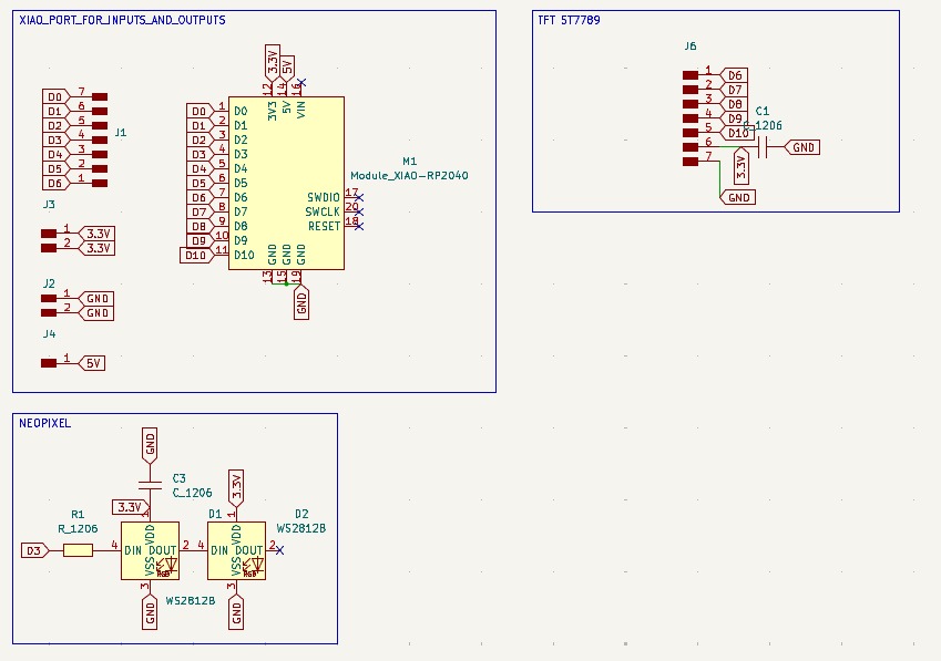
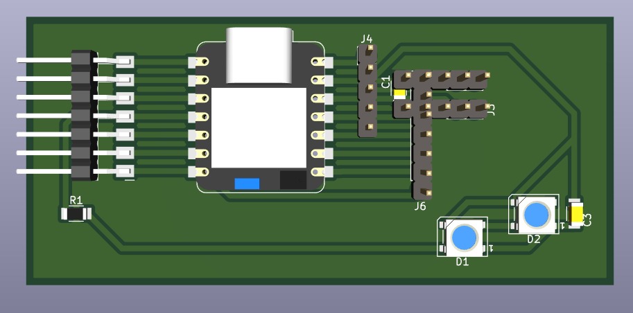
XIAO INPUTS AND OUTPUTS. For the Xiao, I'll just add pins for its inputs and outputs, and I'll also add pins for external power supply (3.3V, 5V, and GND).
NeoPixels. I connected them to D3 on my Xiao using a resistor and a label, then connected the LEDs in series and the first power pin to a capacitor of 100 nF for component safety. Finally, I left some holes so that more LEDs could be added if desired.
Display. For the display output I just added the corresponding pins to connect it later and a decoupling capacitor to 3.3V.
PCB design
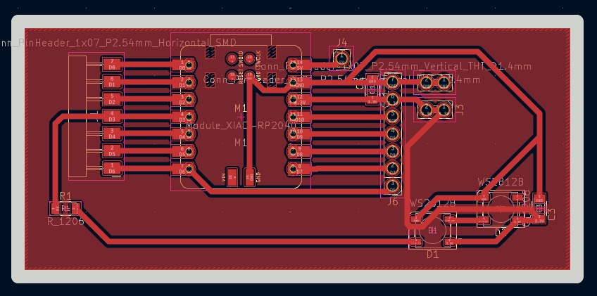
1. Then I went to the PCB editor and with the Route single track I connected every component.
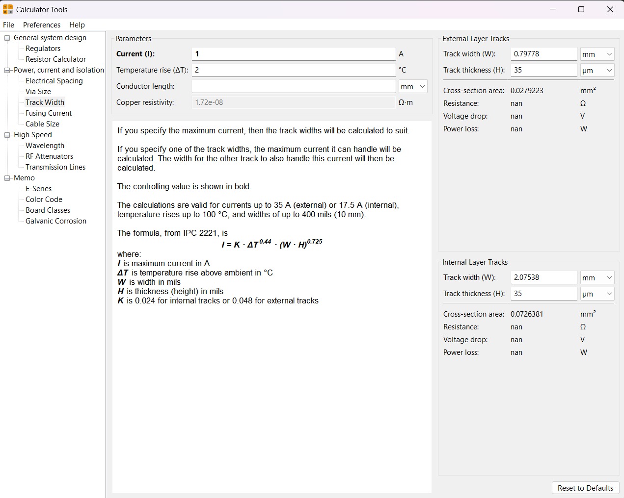
Calculator tool. Before defining the size, it is important to calculate it using the calculator tool given by KiCad. To do that we first have to go to the start menu and open the Calculator tool.Then add the Current (I) and the Temperature rise we are expecting our PCB to have and look fo the result the calculator will give back to us in the right top side. The calculator works by using a formula explained at the bottom.
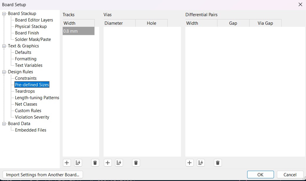
Track thickness. To change the track thickness we must go to the top tool section and click on Track use netclass width. Subsequently, select Edit Pre-defined Sizes.
Inside that section we can add tracks sizes by clicking the + symbol located at the bottom of the window, and in the width section we can change the width of the new track we added. Then we'll just have to click Ok.
MODS
This are the parameters for each process in Mods. If you want to learn more go to Week 8.
Parameters.• The outline width is 2 mm and its layer is Edge.Cuts.• The track’s width is 0.8 mm- 2 mm and its layer is F.Cu.• The Holes layer is User.1.
Drilling - MODS.
• Tool width. 0.8 mm• Speed. 0.5 mm/s• Origin (x,y,z). (0,0,0)• Offset number. 1
Cutting - MODS.
• Tool width. 0.39 mm• Speed. 4 mm/s• Origin (x,y,z). (0,0,0)•Offset number. 3
Outline - MODS.
• Tool width. 2 mm• Speed. 4 mm/s• Origin (x,y,z). (0,0,0)• Offset number. 1
Results
VPANEL
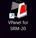
VPanel for the Roland DG Corporation SRM-20 is the dedicated, user-friendly computer software interface used to operate, control, and monitor the desktop milling machine. It acts as a virtual on-screen panel, enabling users to set the milling origin (XYZ base point), adjust feed rates and spindle speeds, and pause/resume jobs.
Before Cutting
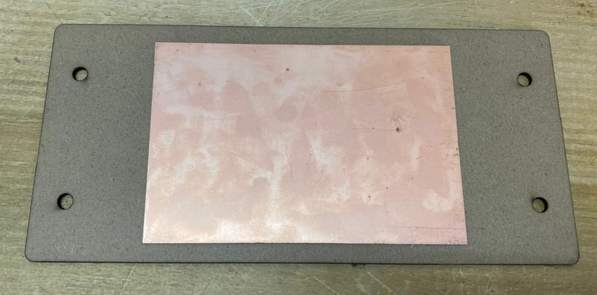
1. First, we have to paste the tape in the back of the copper board.
2. Then, we have to paste the copper board to the Sacrifice Bed.
Materials:
Copper Board.
double-sided tape.
Sacrifice Bed. Is an MDF board designed to prevent the SMR-20 from being damaged in the event that the tool drills too deep.
Before Cutting
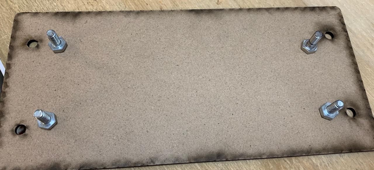
3. Subsequently, we have to place the bed inside the SMR-20. In my case, in my lab, our SMR-20 has a fitting to secure the sacrifice table with screws.
Before Cutting
4. Having secured the bed inside the SMR-20, we have to select the tool for each milling process (Holes, Tracks and Borders).
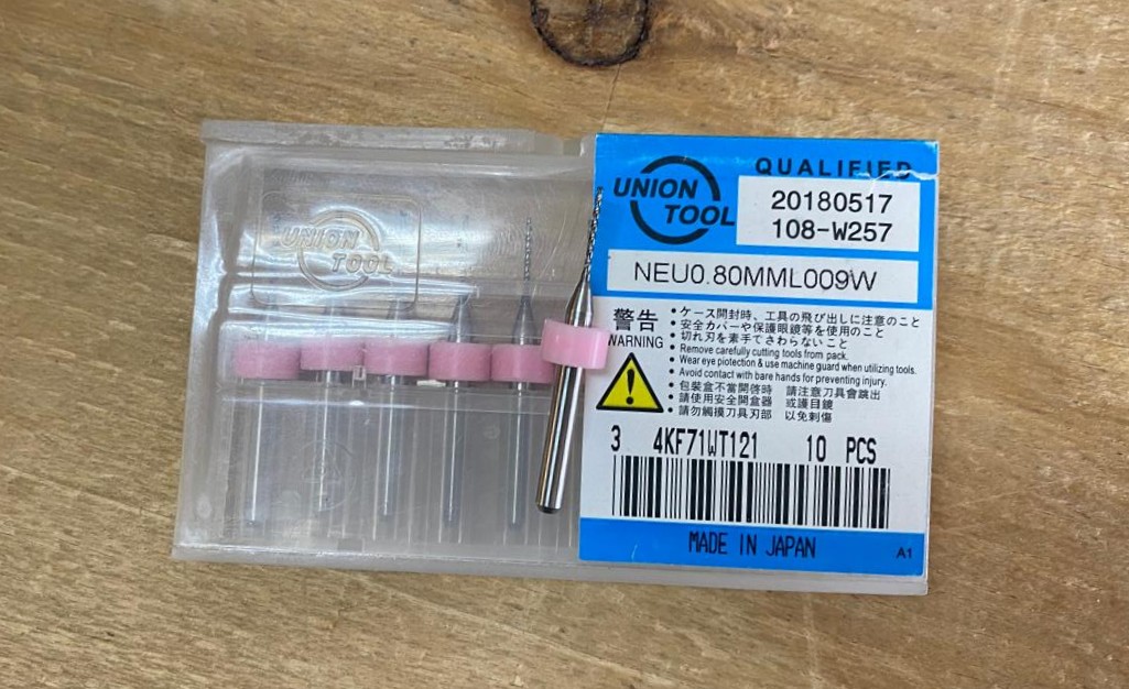
Drilling Tool. This tool is specifically for perforations because of its shape and width. To use it, we must set the speed between 0.1 and 0.5 in order to don't damage it.
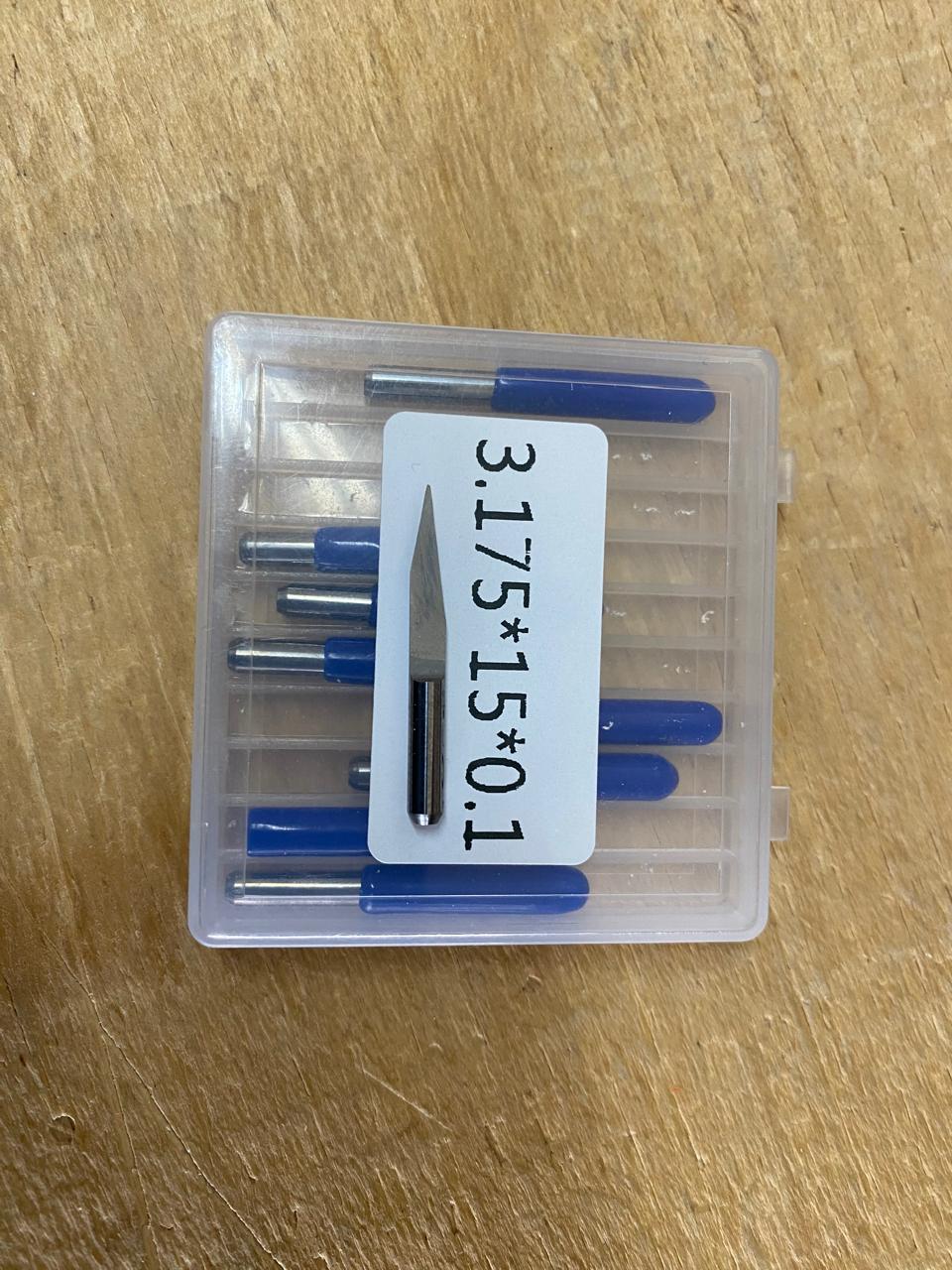
Cutting tool. This tool is specifically designed for traces, as its point is sharp and very thin. The Speed of use can be higher but we must be careful about its deep.
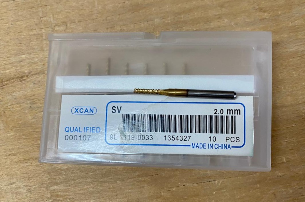
Border tool. This tool is can be used for the border cutting because of its width, it can also be used for perforation, but the diameter of them will be bigger.
Cutting
1. We have to connect our computer to the SMR-20 and open VPANEL.
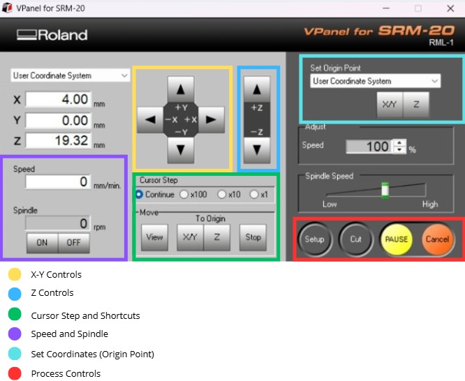
VPANEL.
X-Y Controls. Move the tool in the X-Y axis.
Z Controls.Move the tool in the Z axis.
Cursor Step and Shortcuts. The Step Cursor determines the speed at which the tool moves along all axes; Continue is the smoothest and x1 is the slowest setting, since each click corresponds to a single motor movement. The Shortcuts are to automatically move to an already saved point (Origin Point).
Speed and Spindle. Is to set the speed and to turn on or turn off the the spin of the tool.
Set Coordinates (Origin Point). By clicking the XY or the Z button we can set the Origin Point.
Process Controls. Cut is for adding our code and start the process. Pause, this allows you to pause the process and resume it from where it left off. Stop, stops the process.
Cutting
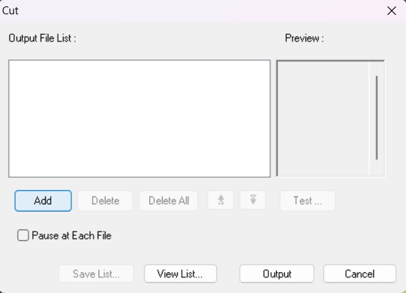
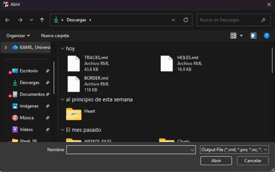
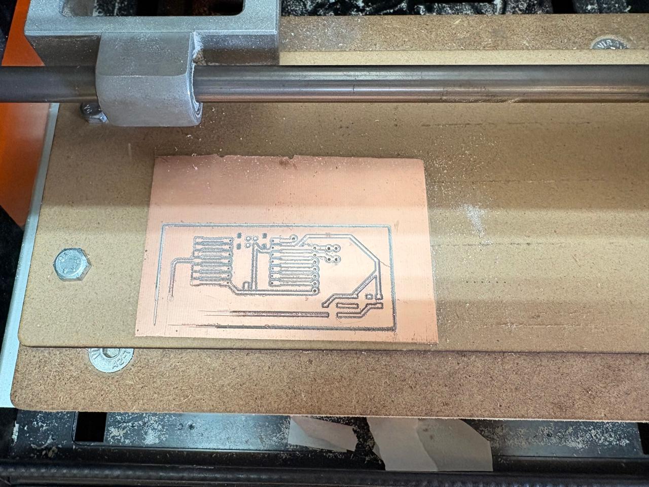
2. Then we have to click on Cut. A window will open, and we should click Add to add our milling code.
3. Finally we have to click Output and the machine will automatically start to cut.
Cutting
Soldering
1. To solder, we first need to set up our workspace and gather the necessary tools.
Necessary tools
- Soldering station
- Flux
- Soldering Tin
- Desoldering mesh
- Silicone Tablecloth
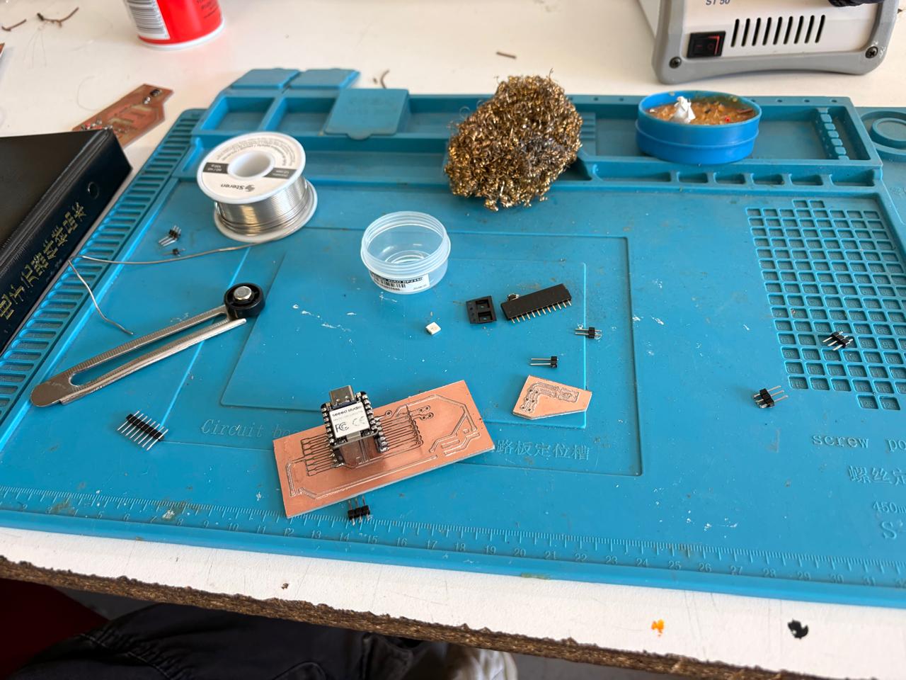
Components
- Pinheaders
- 1 Jumper
- 2 smd WS2812B
Soldering
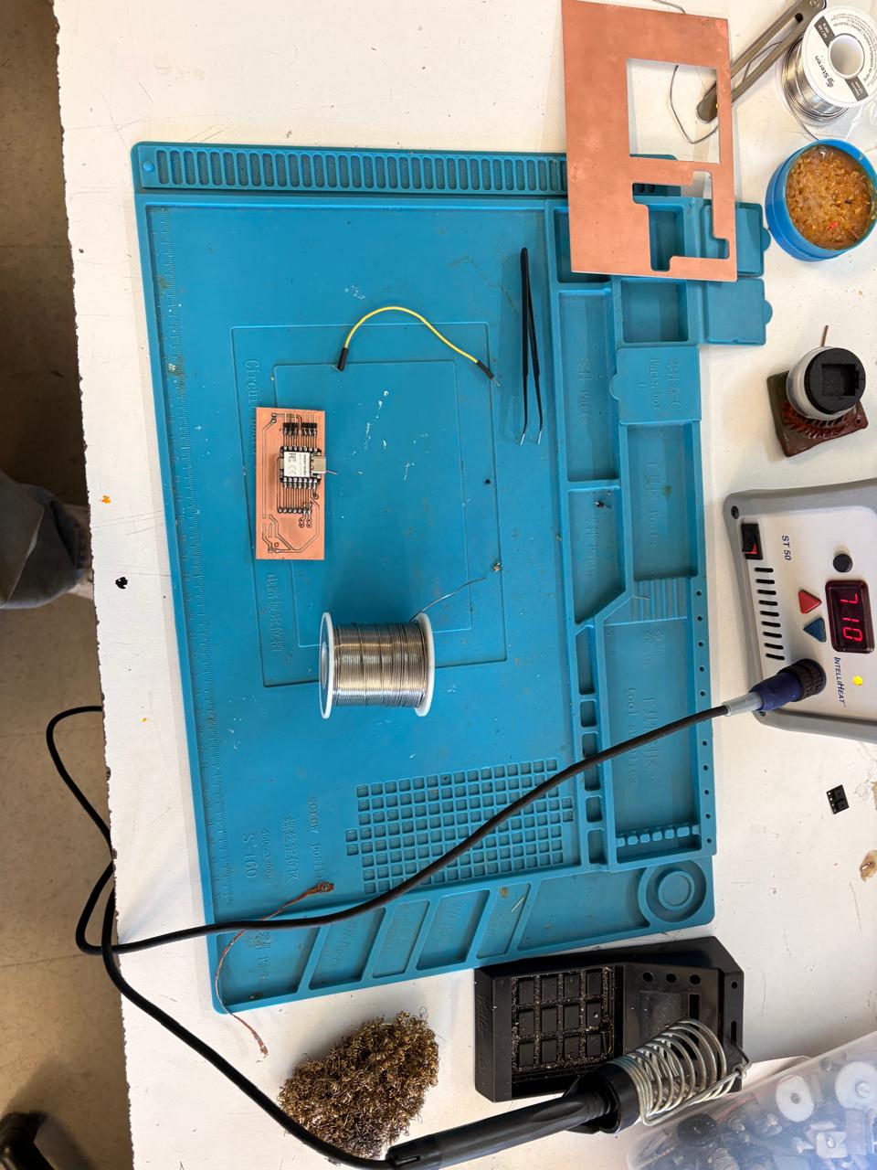
2. First, we need to apply flux to our PCB so that the solder adheres better. I placed the Xiao over the pins so it would stand upright.
Soldering
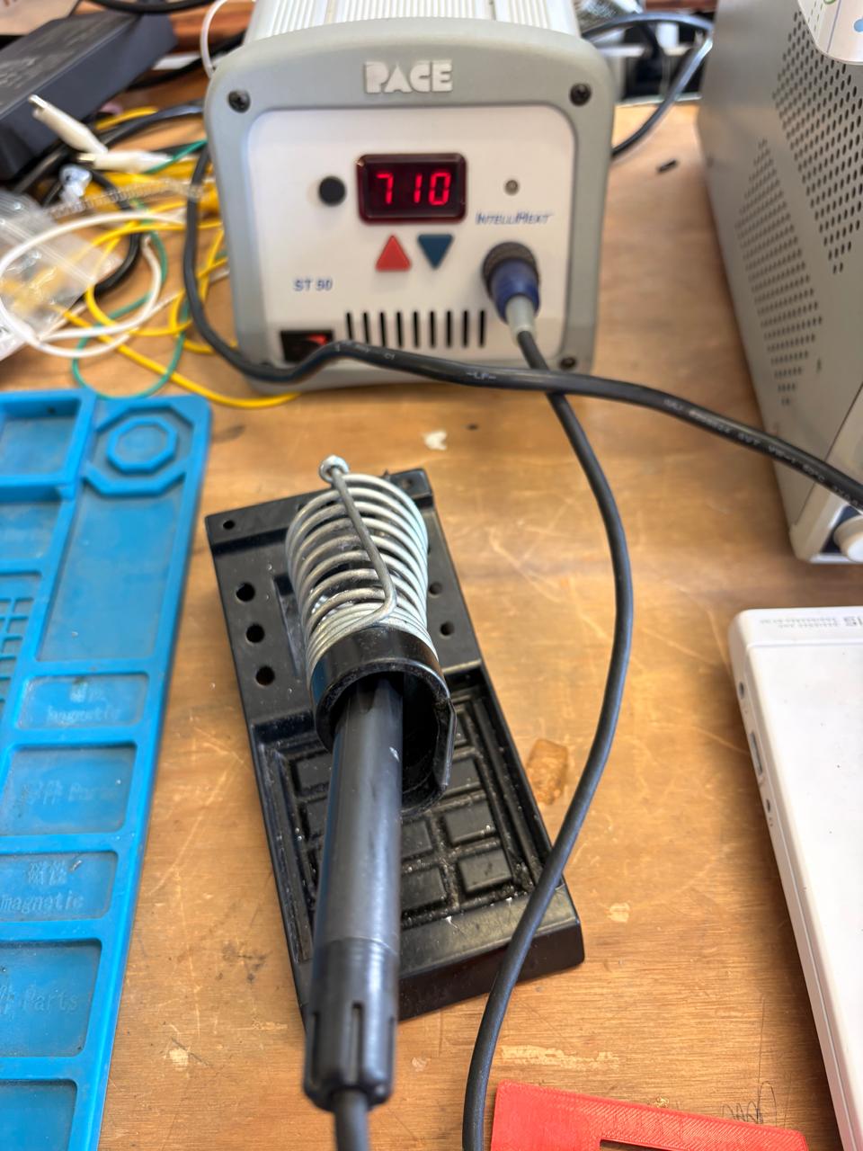
3.Then, we have to turn on the soldering station and set the temperature. To solder tin it is recomendable to place the temperature above 300 °C (572 °F). I will use 375 °C (710 °F) because that works good with my materials.
4.To solder, we have to place the soldering iron over the copper board and heat it up, then we have to place the Tin on the surface and wait until it melts. It is important to place the Tin on the copper surfance and not on the soldering iron because the melted Tin flows toward hot surfaces, if we place it on the soldering iron, it won't adhere easily to the copper surface because it will be cooler.
Results
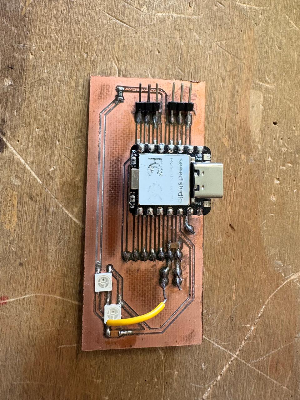
Note.During the design of the PCB, I forgot to connect my neopixels to voltage, so I solved it using a little cable and soldering it to one 3.3V pin. Then I had some trouble with the alimentaton because I forgot that the neopixels requiere more than 3.3V to perform properly.
Step Response Sensor
Schematic
I made this sensor with the help of Adrian Torres documentation, Neil Gershenfeld's examples and Robert Hart's page.
What this sensor does is that its reading increases when we bring the plates closer together, since the distance between the two copper pieces decreases, causing a change in capacitance. The closer the plates are, the greater the capacitance.
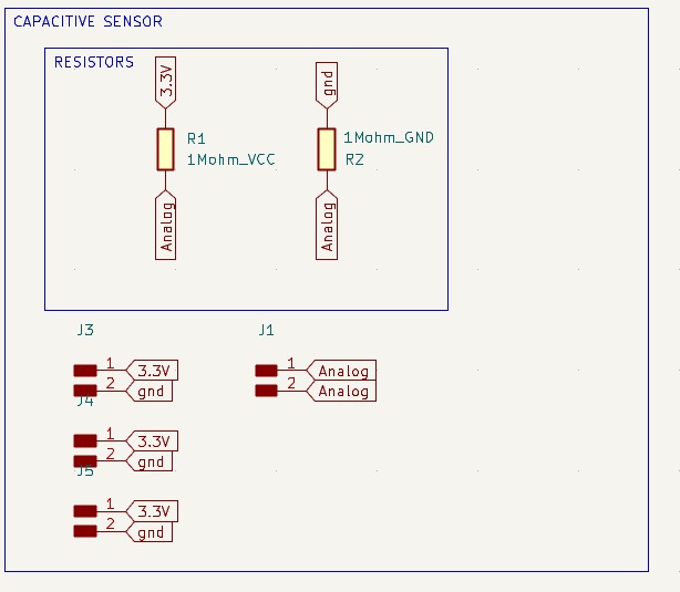
Step Response. This board only has the pins needed to connect the step-response sensor to the microcontroller. It consists of two analog pins; one is connected to GND and the other to 3.3V via two 1-megohm resistors. After that, I simply added pins for power.
PCB design
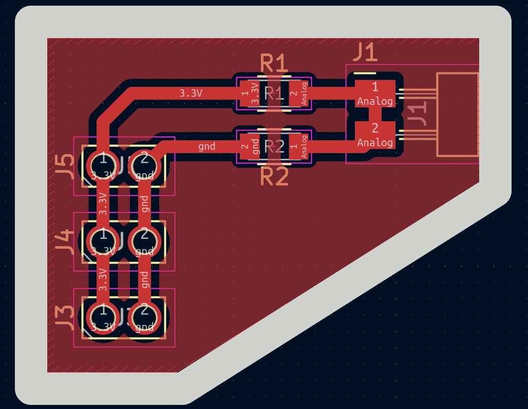
1. Then I went to the PCB editor and with the Route single track I connected every component.
Calculator tool. Before defining the size, it is important to calculate it using the calculator tool given by KiCad. To do that we first have to go to the start menu and open the Calculator tool.Then add the Current (I) and the Temperature rise we are expecting our PCB to have and look fo the result the calculator will give back to us in the right top side. The calculator works by using a formula explained at the bottom.
Track thickness. To change the track thickness we must go to the top tool section and click on Track use netclass width. Subsequently, select Edit Pre-defined Sizes.
Inside that section we can add tracks sizes by clicking the + symbol located at the bottom of the window, and in the width section we can change the width of the new track we added. Then we'll just have to click Ok.
MODS
This are the parameters for each process in Mods. If you want to learn more go to Week 8.
Parameters.• The outline width is 2 mm and its layer is Edge.Cuts.• The track’s width is 0.8 mm- 2 mm and its layer is F.Cu.• The Holes layer is User.1.
Drilling - MODS.
• Tool width. 0.8 mm• Speed. 0.5 mm/s• Origin (x,y,z). (0,0,0)• Offset number. 1
Cutting - MODS.
• Tool width. 0.39 mm• Speed. 4 mm/s• Origin (x,y,z). (0,0,0)•Offset number. 3
Outline - MODS.
• Tool width. 2 mm• Speed. 4 mm/s• Origin (x,y,z). (0,0,0)• Offset number. 1
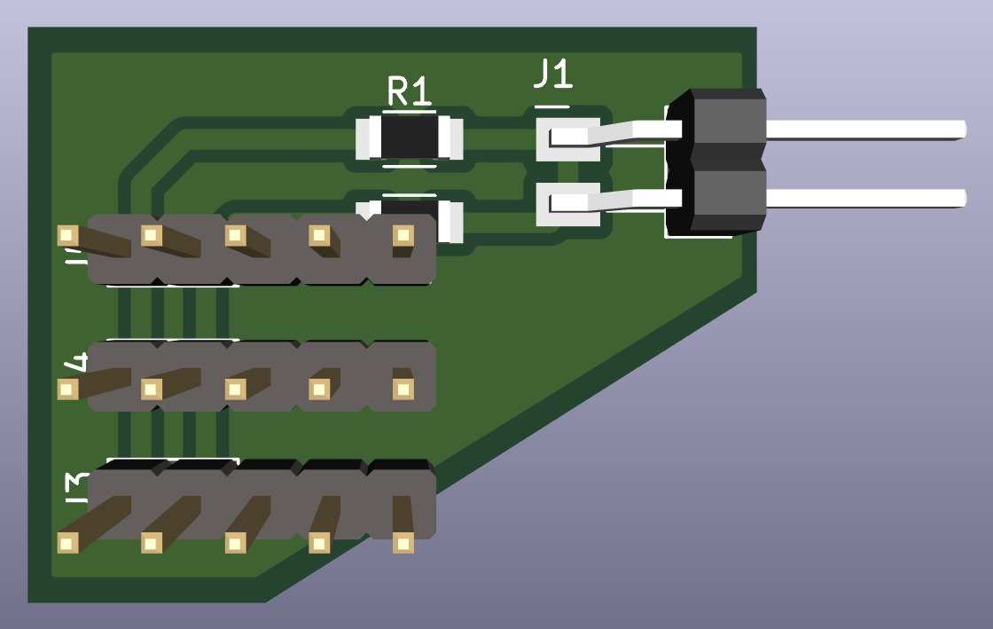
3D view
How to make the sensor
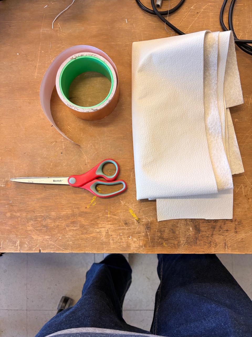
1. First I gathered all the materials.
Necessary materials
- Non-conductive material
- Copper tape
- Scissors
- Wire or Jumpers
How to make the sensor
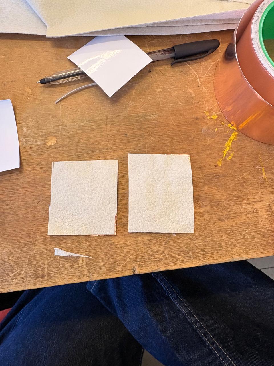
2. Then we have to cut the Non-conductive material in the shape we desire.
How to make the sensor
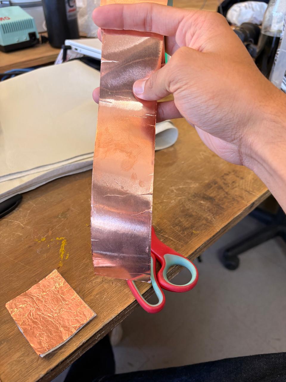
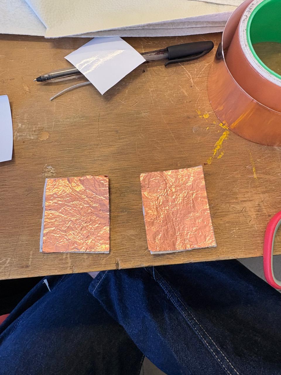
3. Then we have to cut the Copper tape and paste it over the other material.
How to make the sensor
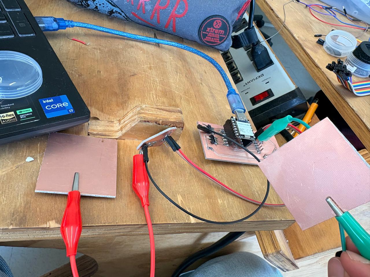
4. Then we have to connect it. To connect the board with the sensor we must conect one layer to a digital pin and the other layer to the Step response board analog pin and the other analog pin to one microcontrollers analog pin. then connect the power supply pins to power.
How does it work?
1. I made this sensor with the help of Adrian Torres' documentation and Neil Gershenfeld's examples.
2. Then, we have to paste the copper board to the Sacrifice Bed.
Materials:
Copper Board.
double-sided tape.
Sacrifice Bed. Is an MDF board designed to prevent the SMR-20 from being damaged in the event that the tool drills too deep.
Before Cutting
3. Subsequently, we have to place the bed inside the SMR-20. In my case, in my lab, our SMR-20 has a fitting to secure the sacrifice table with screws.
Before Cutting
4. Having secured the bed inside the SMR-20, we have to select the tool for each milling process (Holes, Tracks and Borders).
Drilling Tool. This tool is specifically for perforations because of its shape and width. To use it, we must set the speed between 0.1 and 0.5 in order to don't damage it.
Cutting tool. This tool is specifically designed for traces, as its point is sharp and very thin. The Speed of use can be higher but we must be careful about its deep.
Border tool. This tool is can be used for the border cutting because of its width, it can also be used for perforation, but the diameter of them will be bigger.
Cutting
1. We have to connect our computer to the SMR-20 and open VPANEL.
VPANEL.
X-Y Controls. Move the tool in the X-Y axis.
Z Controls.Move the tool in the Z axis.
Cursor Step and Shortcuts. The Step Cursor determines the speed at which the tool moves along all axes; Continue is the smoothest and x1 is the slowest setting, since each click corresponds to a single motor movement. The Shortcuts are to automatically move to an already saved point (Origin Point).
Speed and Spindle. Is to set the speed and to turn on or turn off the the spin of the tool.
Set Coordinates (Origin Point). By clicking the XY or the Z button we can set the Origin Point.
Process Controls. Cut is for adding our code and start the process. Pause, this allows you to pause the process and resume it from where it left off. Stop, stops the process.
Cutting
2. Then we have to click on Cut. A window will open, and we should click Add to add our milling code.
3. Finally we have to click Output and the machine will automatically start to cut.
Cutting
Sharp IR Distance
Sensor
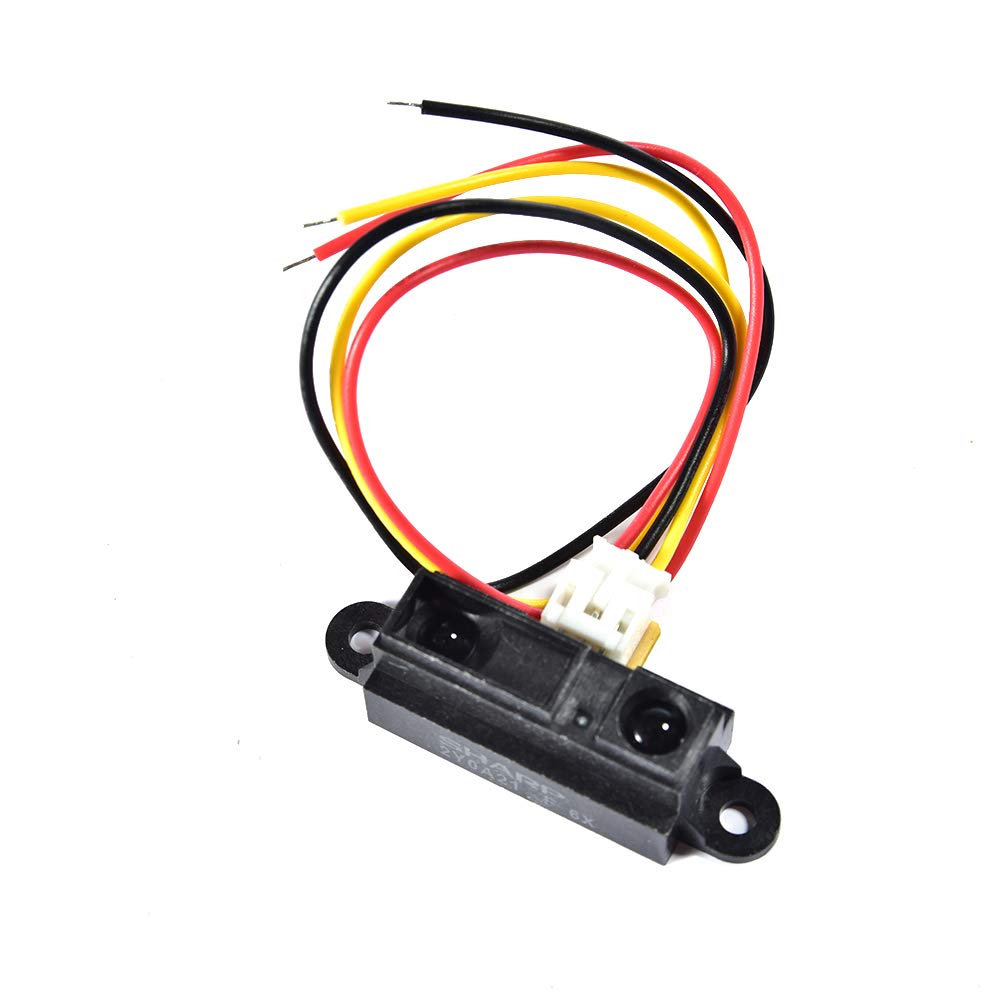
is a distance measuring sensor unit, composed of an integrated combination of PSD (position sensitive detector) , IR-LED (infrared emitting diode) and signal processing circuit. The variety of the reflectivity of the object, the environmental temperature and the operating duration are not influenced easily to the distance detection because of adopting the triangulation method. This device outputs the voltage corresponding to the detection distance. So this sensor can also be used as a proximity sensor.
Datasheet: Sharp IR Distance
How to connect.To connect it, simply connect the red wire to 5V, the black wire to GND, and the yellow wire to any analog pin on the microcontroller.
How does it work?
1. I made this sensor with the help of Adrian Torres' documentation and Neil Gershenfeld's examples.
2. Then, we have to paste the copper board to the Sacrifice Bed.
Materials:
Copper Board.
double-sided tape.
Sacrifice Bed. Is an MDF board designed to prevent the SMR-20 from being damaged in the event that the tool drills too deep.
Before Cutting
3. Subsequently, we have to place the bed inside the SMR-20. In my case, in my lab, our SMR-20 has a fitting to secure the sacrifice table with screws.
Before Cutting
4. Having secured the bed inside the SMR-20, we have to select the tool for each milling process (Holes, Tracks and Borders).
Drilling Tool. This tool is specifically for perforations because of its shape and width. To use it, we must set the speed between 0.1 and 0.5 in order to don't damage it.
Cutting tool. This tool is specifically designed for traces, as its point is sharp and very thin. The Speed of use can be higher but we must be careful about its deep.
Border tool. This tool is can be used for the border cutting because of its width, it can also be used for perforation, but the diameter of them will be bigger.
Cutting
1. We have to connect our computer to the SMR-20 and open VPANEL.
VPANEL.
X-Y Controls. Move the tool in the X-Y axis.
Z Controls.Move the tool in the Z axis.
Cursor Step and Shortcuts. The Step Cursor determines the speed at which the tool moves along all axes; Continue is the smoothest and x1 is the slowest setting, since each click corresponds to a single motor movement. The Shortcuts are to automatically move to an already saved point (Origin Point).
Speed and Spindle. Is to set the speed and to turn on or turn off the the spin of the tool.
Set Coordinates (Origin Point). By clicking the XY or the Z button we can set the Origin Point.
Process Controls. Cut is for adding our code and start the process. Pause, this allows you to pause the process and resume it from where it left off. Stop, stops the process.
Cutting
2. Then we have to click on Cut. A window will open, and we should click Add to add our milling code.
3. Finally we have to click Output and the machine will automatically start to cut.
Cutting
Learning outcomes
This week I learned how to build capacitive sensors and how they work. I also came to understand how useful this type of sensor is for my final project, which involves detecting impacts and measuring reaction times. In addition, I learned how proximity sensors work and how to program them.