Week 8: Electronics production
Group assignment
Week 8Introduction
Electronic production (or electronics manufacturing) is the industrial process of designing, prototyping, assembling, testing, and packaging electronic components and devices.
A Printed Circuit Board (PCB) is a board that mechanically supports and electrically connects electronic components using conductive copper traces embedded within insulating material layers.
PCBs are built by alternating layers of copper and non-conductive laminate. During manufacturing, unwanted copper is etched away to form the intended circuit traces. The layers are then laminated together to create the final board structure.
After fabrication, components are mounted on the outer layers. Surface-mount devices (SMD) are placed automatically, while through-hole components may be inserted manually or by machine. The board is then soldered using reflow or wave soldering. Finally, a solder mask and silkscreen are applied to protect the board and label component locations.
For more information you can access to my Week 6.
Export Design
Export as SVG
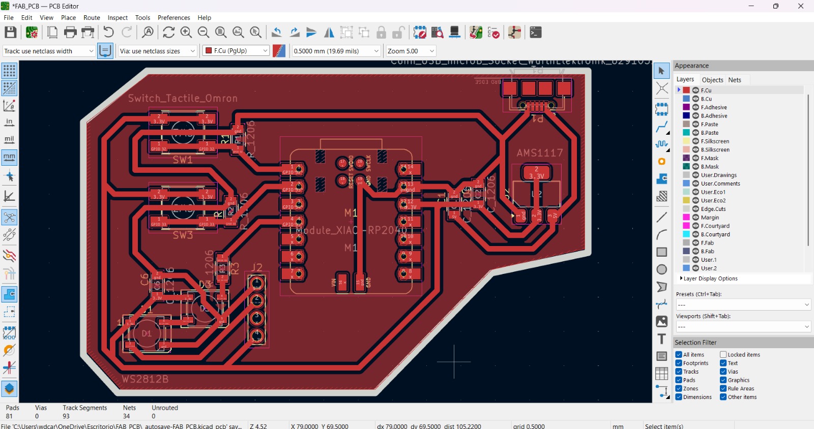
The Design I'll use, is the one that I made in my Week 6.
Export as SVG
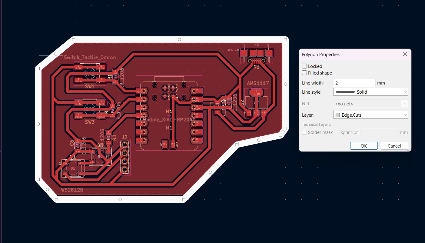
1. First, I changed the border line width to 2 mm because of the tool that will be used later.
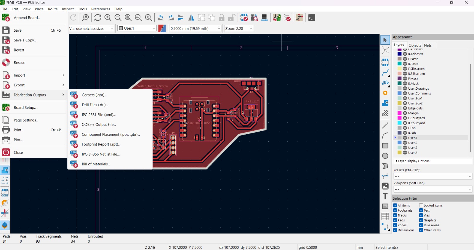
2. Then I went to the top left corner and pressed file, after that I selected Fabrication Outputs.
Export as SVG
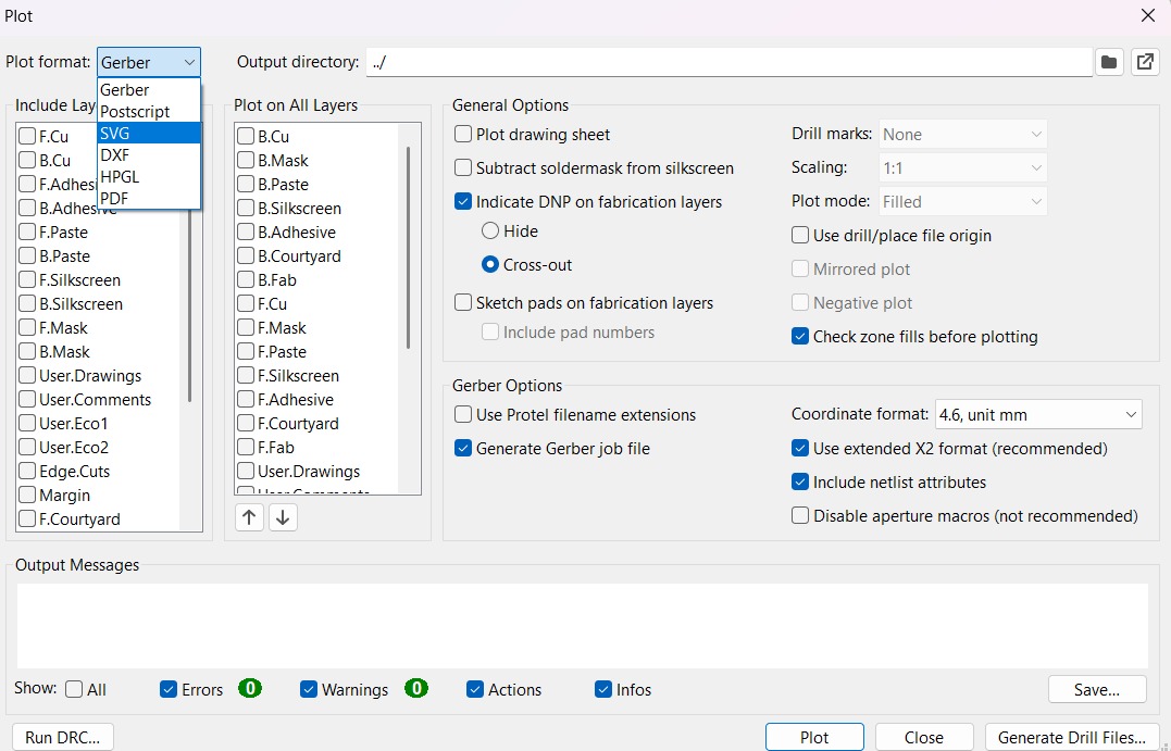
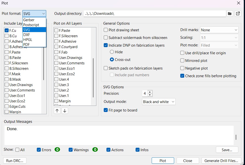
3.In the fabrication outputs we have to select Gerbers. In Gerbers we have to change the plot format to SVG.
4.Having changed the format to SVG, we have to click on Fit page to board to keep the meassures the way they are in the dessign and select the Output Directory.
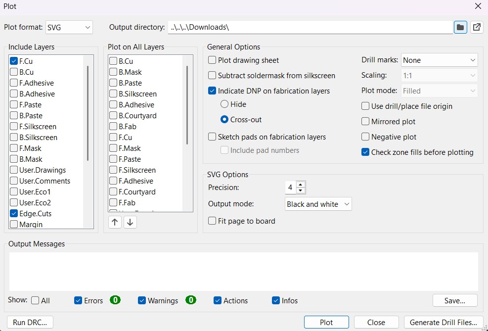
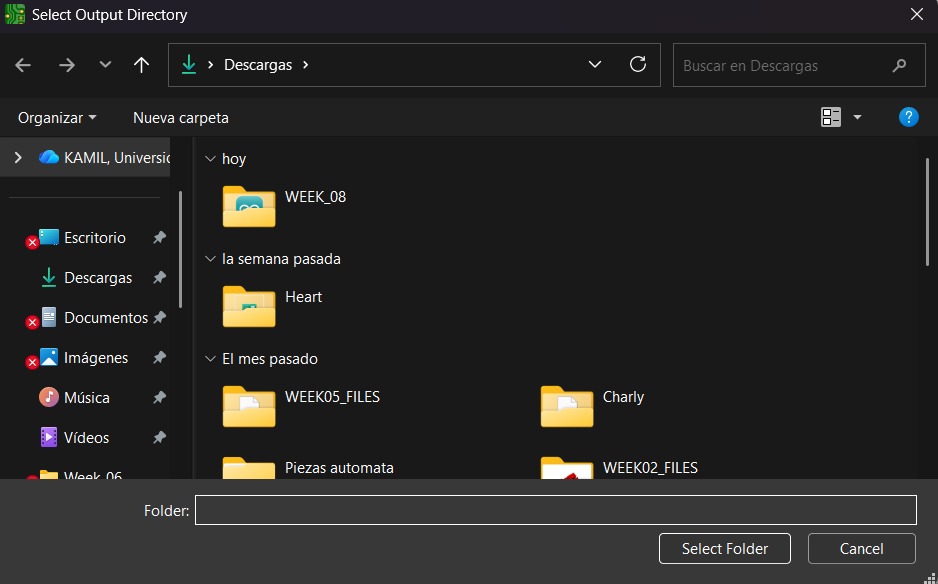
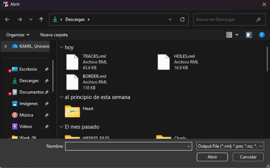
Output Directory To change the Output Directory we have to click on the folder symbol located at the top and select the place in our computer where we want to save our document.
Export as SVG
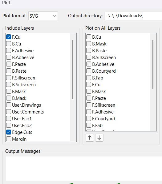
5. Then, we have to select the layers we want to plot.
6. Finally, we have to click on plot and go to the folder where our files are located.
MODS CE
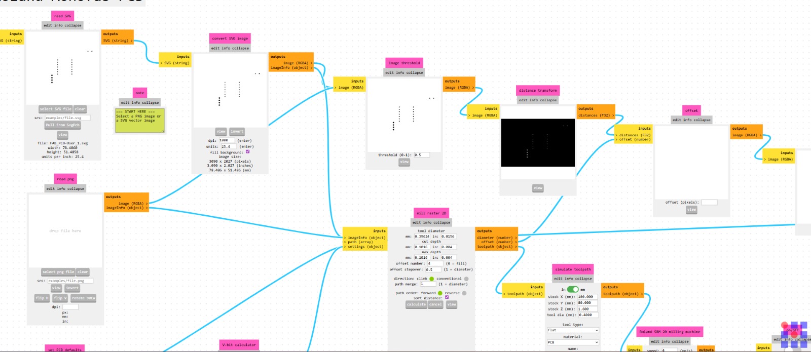
MODS CE is a website that offers a wide range of programs and modules designed to perform various functions. It includes G-CODE programming software for CNC routers such as the Roland SRM-20, which we will use later on.

MODS CE - HOLES
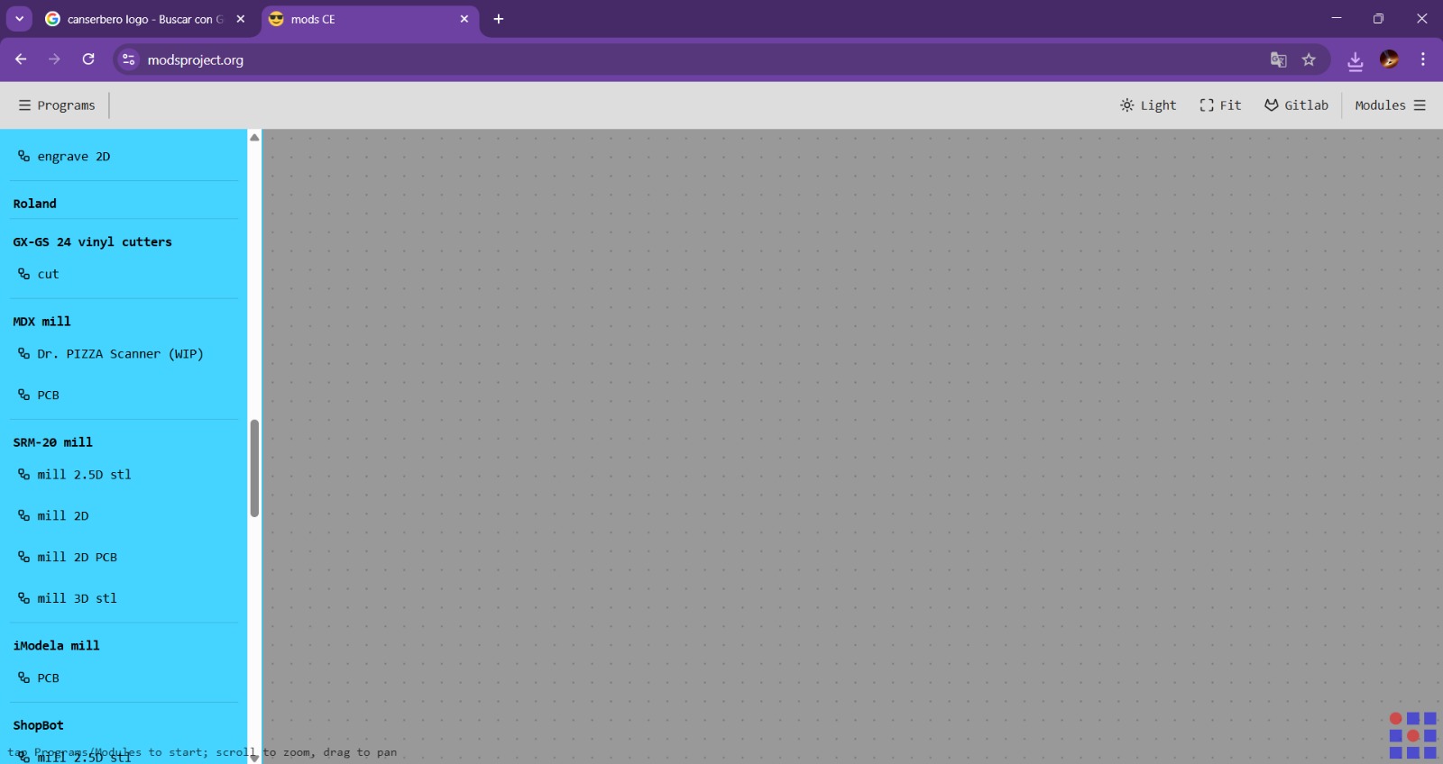
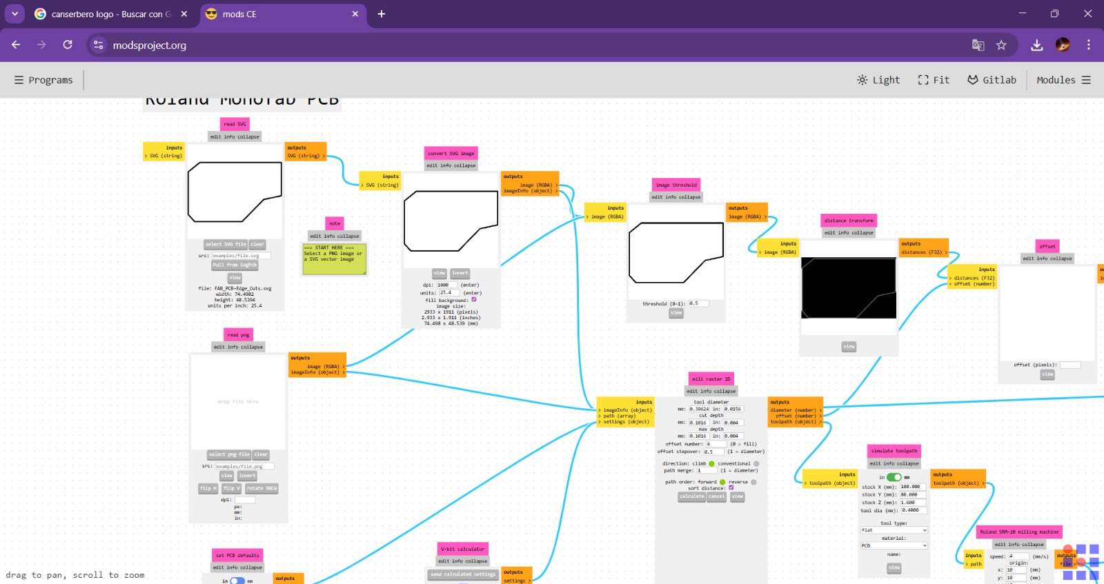
First we need to access to MODS CE, click the top left drop-down menu and look for SRM-20 mill section and select mill 2D PCB.
MODS CE - HOLES
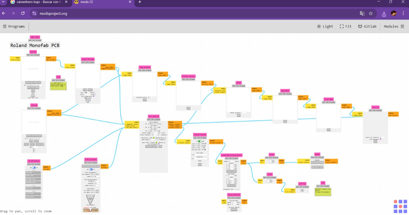
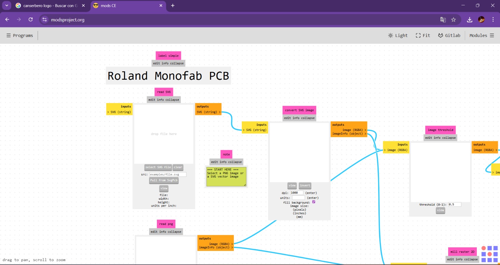
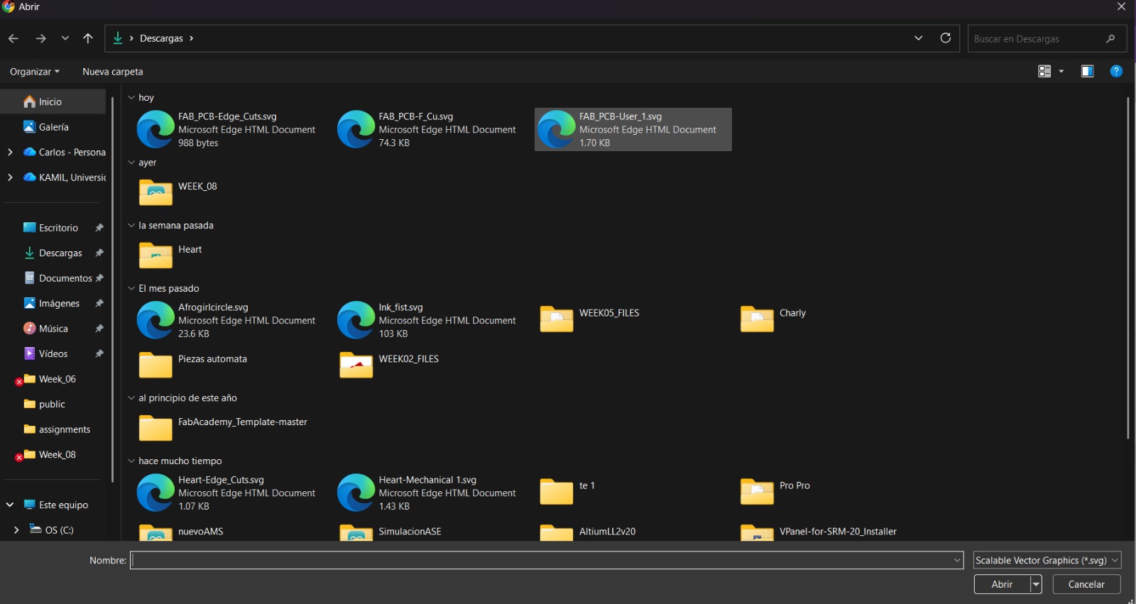
1. Having accesed to mill 2D PCB a workspace will be deployed. First we have to upload our file. To achieve that we have to click select SVG File in the first rectangle.
MODS CE - HOLES
2. Once our file has been uploaded, we need to scroll down to the bottom section and select the size of our tool. Since we'll be drilling holes in this case, we must select the drill tool.
MODS CE - HOLES
Set
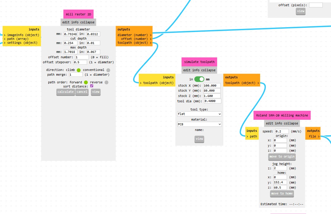
Tool diameter.Cut Depth.Max Depth.Offset Number.To define the tool tip position or compensation values, enabling accurate machining and tool changes.Offset StepOver.Is the horizontal distance (offset) between consecutive tool passes, critical for determining surface finish (scallop height) and machining time.Path Merge.
Process
- Calculate
- Cancel
- View
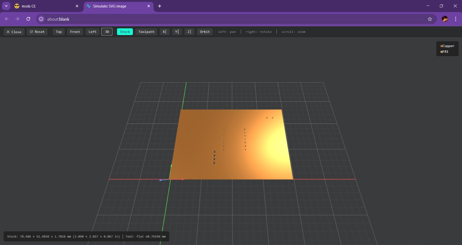
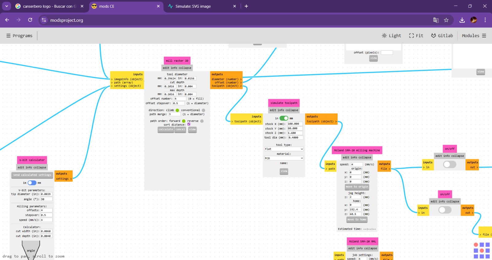
View. To generate the view we have to calculate the process and automatically the page will send us to another window where we can visualize the virtual result.
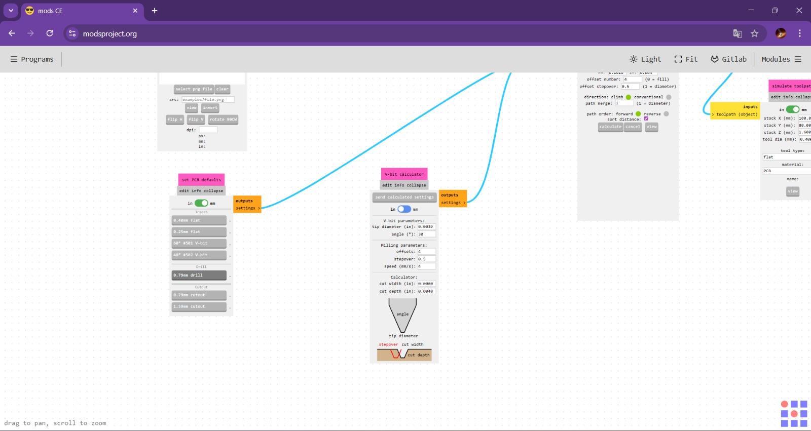
3. Next, in the center, are two modules where we can adjust the actual diameter of our tool; in this case, my tool has the same diameter as the one in the drilling section, so I’m not going to change its size, and in fact, I’m not going to modify any default values, since the holes only need an offset and the depth is correct.
On the right, you can adjust the speed and the initial position of the tool; I recommend setting the speed between 0.2 and 0.5 mm/s to avoid damaging the tool and set the initial position in 0, as shown in the picture.
Parameters.Tool diameter.0.8 mmOffset Number.1Speed.0.2 mm/sPosition(x,y,z).(0,0,0)mmMODS CE - HOLES
4. Finally, we have to enable this option and we have to calculate the process again. After doing this our code will be saved automatically.
MODS CE - TRACKS
First we need to access to MODS CE, click the top left drop-down menu and look for SRM-20 mill section and select mill 2D PCB.
MODS CE - TRACKS
1. Having accesed to mill 2D PCB a workspace will be deployed. First we have to upload our file. To achieve that we have to click select SVG File in the first rectangle.
MODS CE - TRACKS
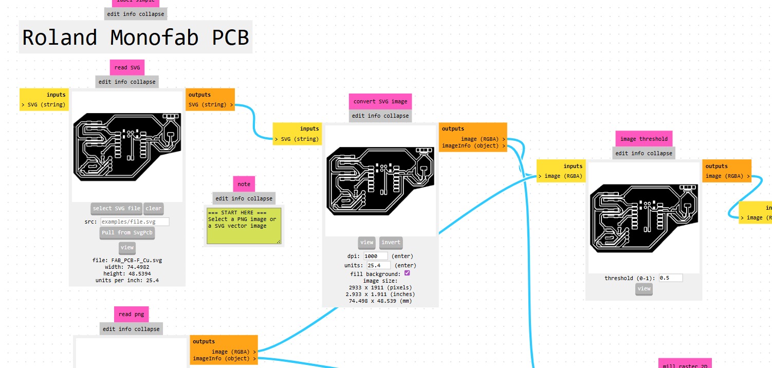
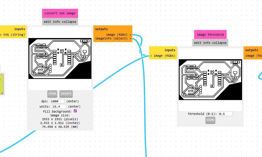
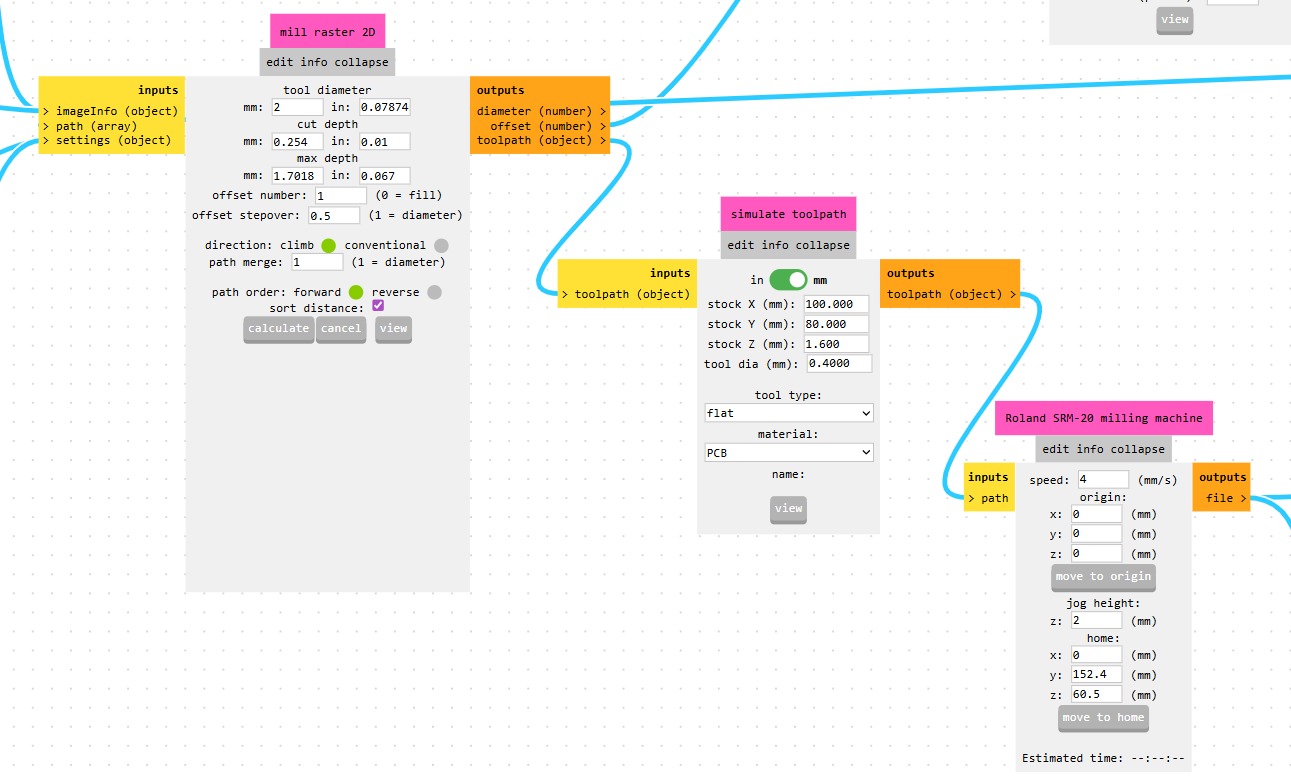
2. Once we've uploaded the file, we need to go to the right side and invert the colors. This is necessary because the machine removes the black areas. Then, we have to scroll down to the bottom section and select the size of our tool. Since we'll be tracing in this case, we must select the flat tool.
MODS CE - TRACKS
Set
Tool diameter.Cut Depth.Max Depth.Offset Number.To define the tool tip position or compensation values, enabling accurate machining and tool changes.Offset StepOver.Is the horizontal distance (offset) between consecutive tool passes, critical for determining surface finish (scallop height) and machining time.Path Merge.
Process
- Calculate
- Cancel
- View
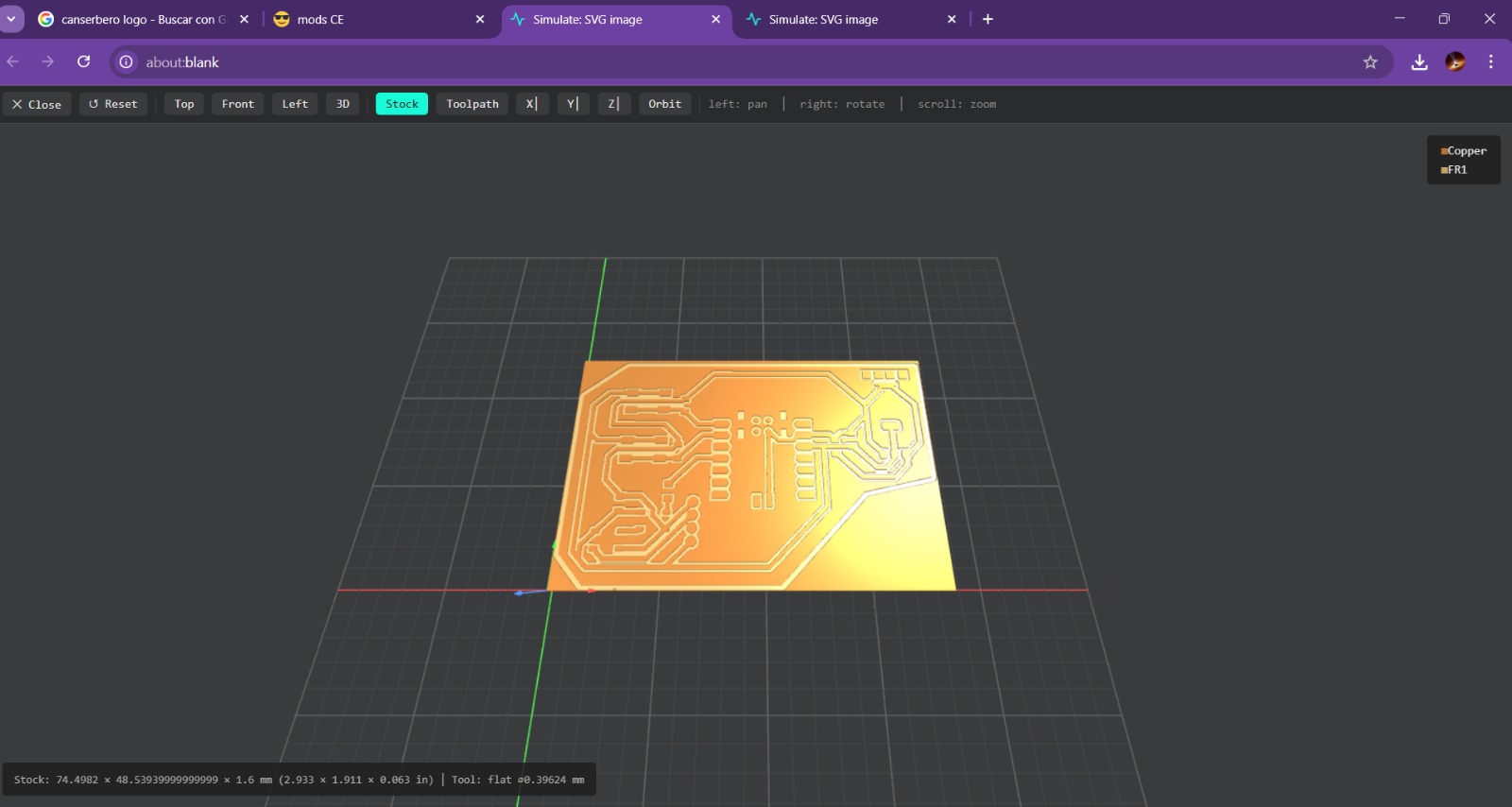
View. To generate the view we have to calculate the process and automatically the page will send us to another window where we can visualize the virtual result.
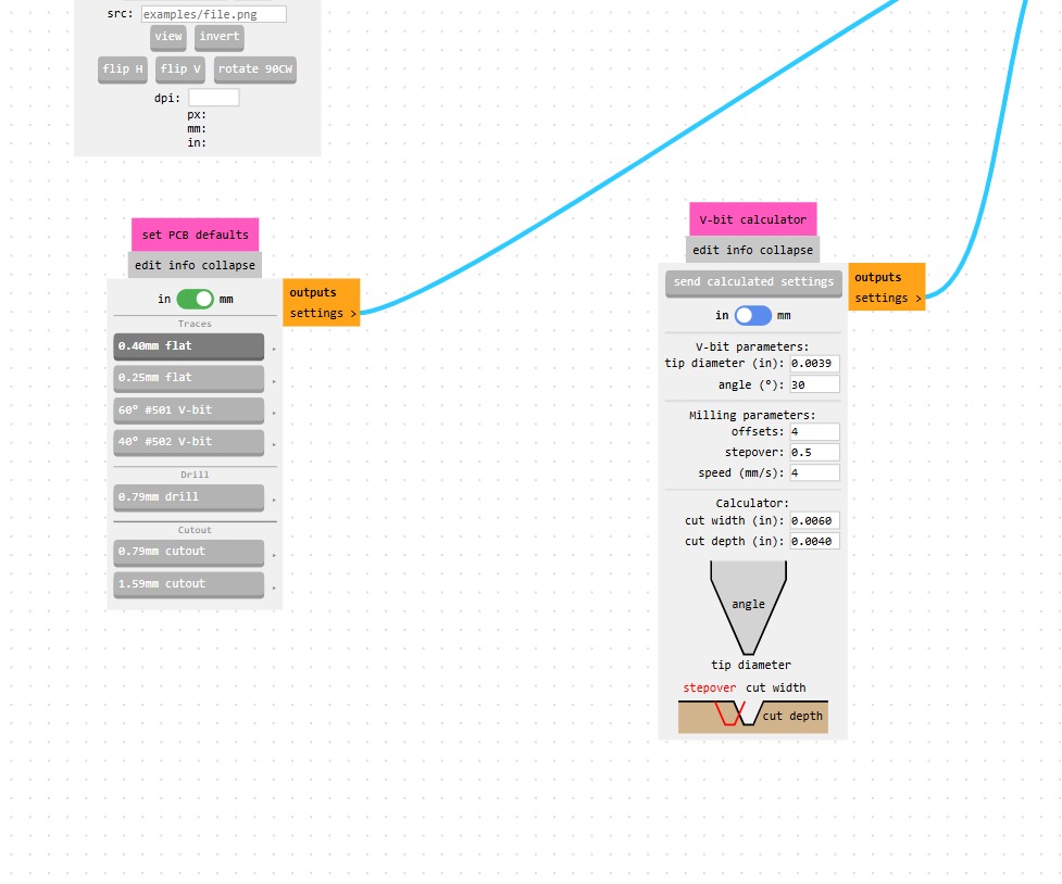
3. Next, in the center, are two modules where we can adjust the actual diameter of our tool; in this case, my tool has the same diameter as the one in the tracing section, so I’m not going to change its size.
On the right, you can adjust the speed and the initial position of the tool. Thanks to the shape of the tool, we can work a little faster than we would with holes.
Parameters.Tool diameter.0.4 mmOffset Number.4Speed.4 mm/sPosition(x,y,z).(0,0,0)mmMODS CE - TRACKS
4. Finally, we have to enable this option and we have to calculate the process again. After doing this our code will be saved automatically.
MODS CE - BORDER
First we need to access to MODS CE, click the top left drop-down menu and look for SRM-20 mill section and select mill 2D PCB.
MODS CE - BORDER
1. Having accesed to mill 2D PCB a workspace will be deployed. First we have to upload our file. To achieve that we have to click select SVG File in the first rectangle.
MODS CE - BORDER
2. Once we've uploaded the file, we have to scroll down to the bottom section and select the size of our tool. Since we'll be doing a perforation in this case, we must select the drill tool.
MODS CE - BORDER
Set
Tool diameter.Cut Depth.Max Depth.Offset Number.To define the tool tip position or compensation values, enabling accurate machining and tool changes.Offset StepOver.Is the horizontal distance (offset) between consecutive tool passes, critical for determining surface finish (scallop height) and machining time.Path Merge.
Process
- Calculate
- Cancel
- View
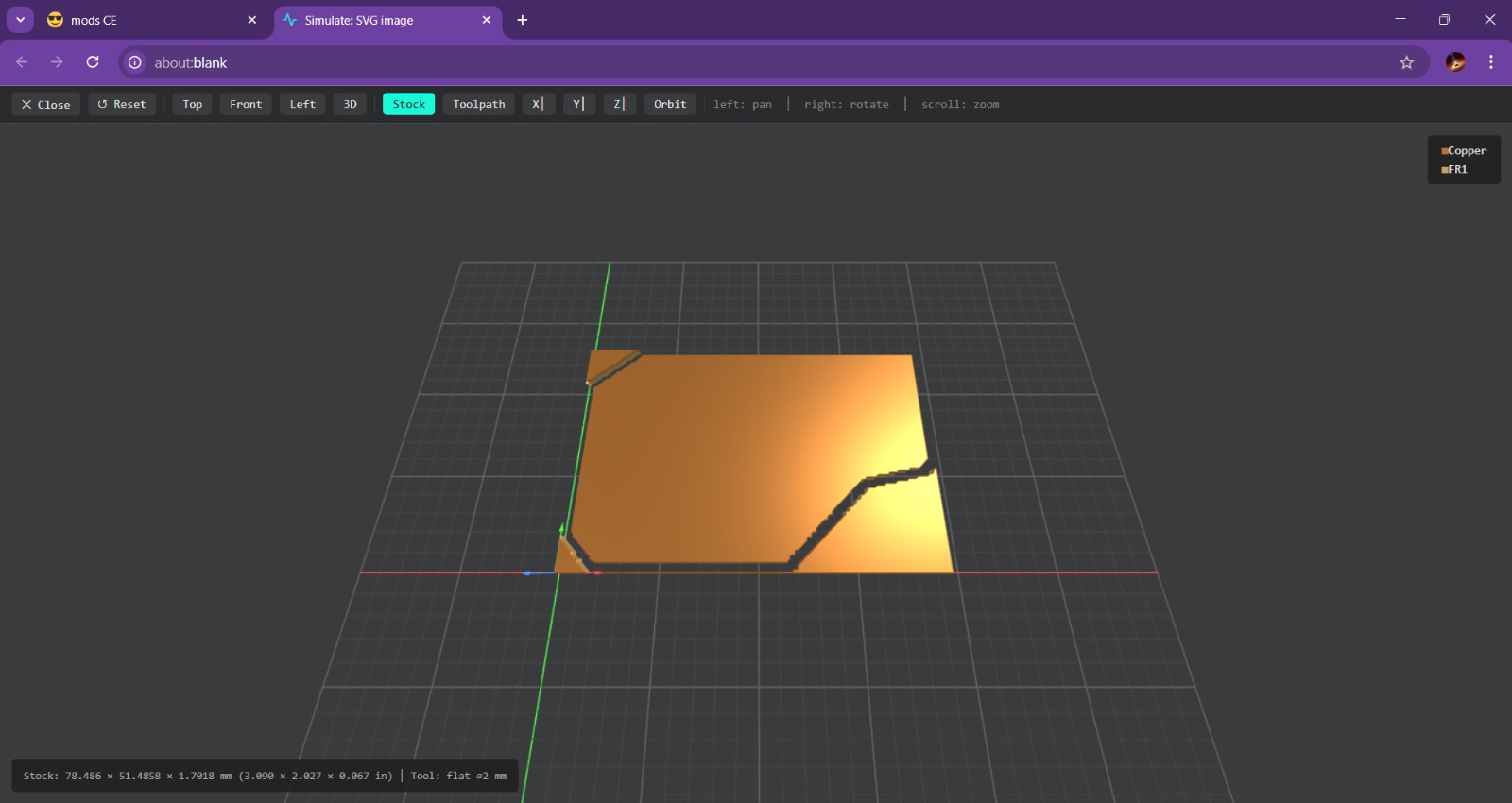
View. To generate the view we have to calculate the process and automatically the page will send us to another window where we can visualize the virtual result.
3. Next, in the center, are two modules where we can adjust the actual diameter of our tool; in this case, my tool doesn't has the same diameter as the one in the drilling section, so I’m going to change it to 2 mm.
On the right, you can adjust the speed and the initial position of the tool. Thanks to the shape of the tool, we can work a little faster than we would with holes.
Parameters.Tool diameter.2 mmOffset Number.1Speed.4 mm/sPosition(x,y,z).(0,0,0)mmMODS CE - BORDER
4. Finally, we have to enable this option and we have to calculate the process again. After doing this our code will be saved automatically.
Roland SRM-20
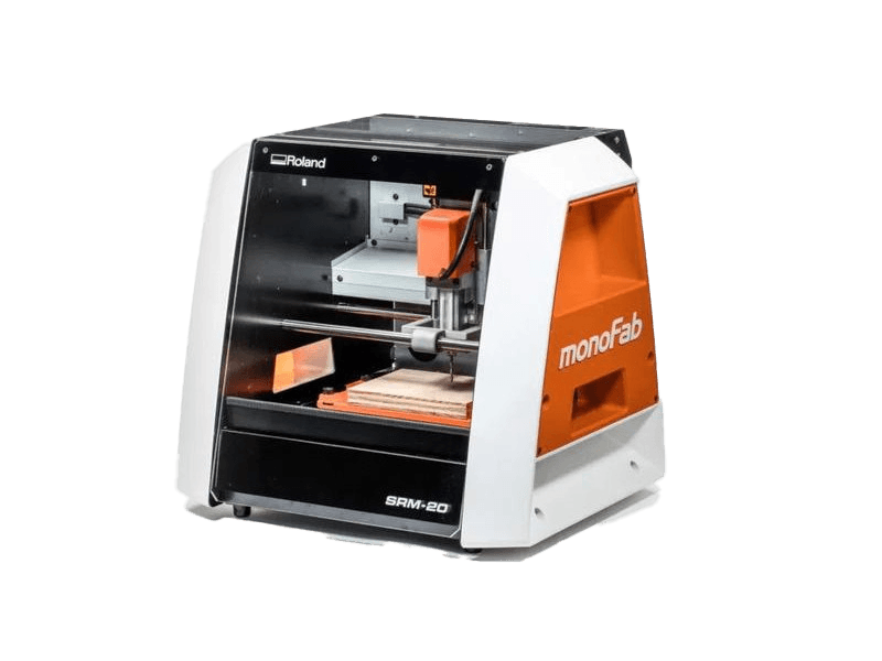
The Roland SRM-20 is a compact CNC desktop milling machine used for prototyping, PCB milling, and small mechanical parts. It removes material using rotating cutting tools.
Work area: 203.2 × 152.4 × 60.5 mm
Table size: 232.2 × 156.6 mm
Spindle speed: 3,000 – 7,000 rpm
Feed rate: 6 – 1800 mm/min
Mechanical resolution: ~0.000998 mm/step
Max workpiece weight: 2 kg
Control interface: USB (RML-1 or NC code)
PCB
VPANEL
VPanel for the Roland DG Corporation SRM-20 is the dedicated, user-friendly computer software interface used to operate, control, and monitor the desktop milling machine. It acts as a virtual on-screen panel, enabling users to set the milling origin (XYZ base point), adjust feed rates and spindle speeds, and pause/resume jobs.
Before Cutting
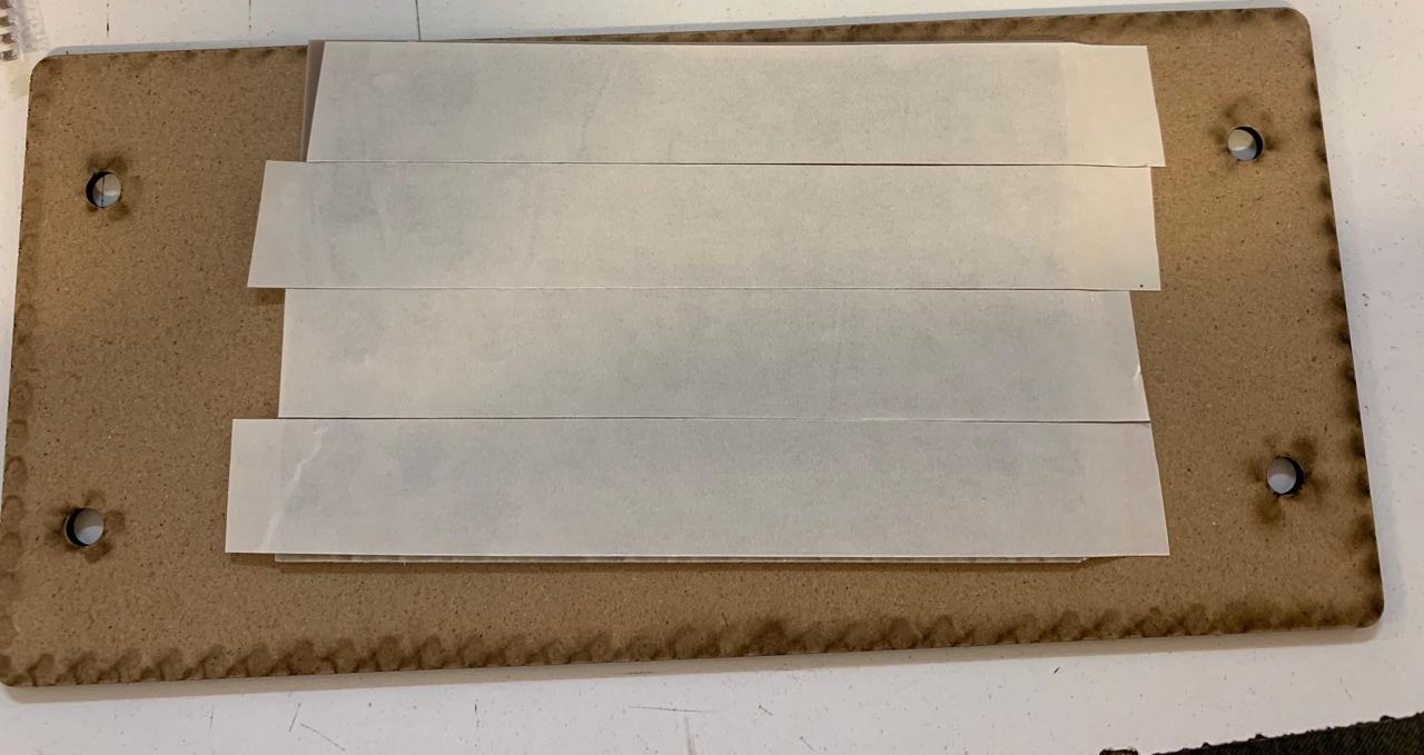
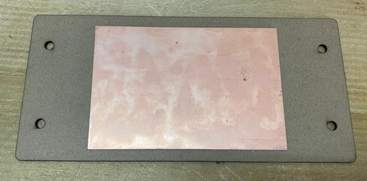
1. First, we have to paste the tape in the back of the copper board.
2. Then, we have to paste the copper board to the Sacrifice Bed.
Materials:
Copper Board.
double-sided tape.
Sacrifice Bed. Is an MDF board designed to prevent the SMR-20 from being damaged in the event that the tool drills too deep.
Before Cutting
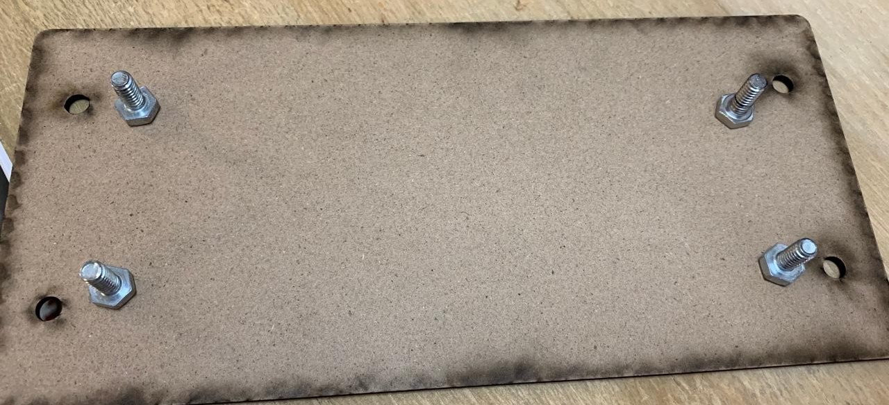
3. Subsequently, we have to place the bed inside the SMR-20. In my case, in my lab, our SMR-20 has a fitting to secure the sacrifice table with screws.
Before Cutting
4. Having secured the bed inside the SMR-20, we have to select the tool for each milling process (Holes, Tracks and Borders).
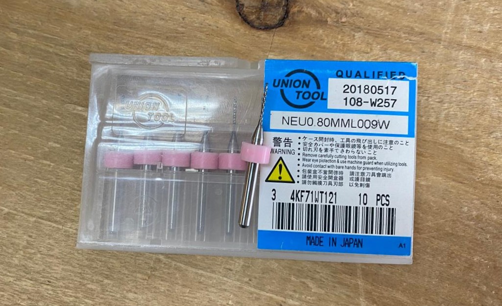
Drilling Tool. This tool is specifically for perforations because of its shape and width. To use it, we must set the speed between 0.1 and 0.5 in order to don't damage it.
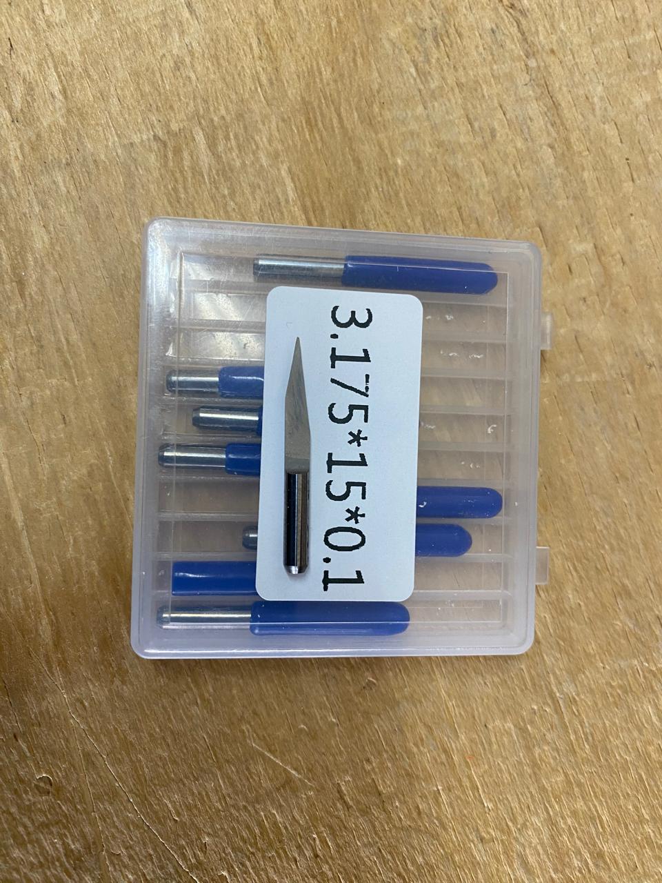
Cutting tool. This tool is specifically designed for traces, as its point is sharp and very thin. The Speed of use can be higher but we must be careful about its deep.
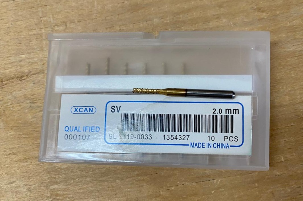
Border tool. This tool is can be used for the border cutting because of its width, it can also be used for perforation, but the diameter of them will be bigger.
Cutting
1. We have to connect our computer to the SMR-20 and open VPANEL.
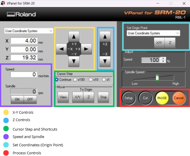
VPANEL.
X-Y Controls. Move the tool in the X-Y axis.
Z Controls.Move the tool in the Z axis.
Cursor Step and Shortcuts. The Step Cursor determines the speed at which the tool moves along all axes; Continue is the smoothest and x1 is the slowest setting, since each click corresponds to a single motor movement. The Shortcuts are to automatically move to an already saved point (Origin Point).
Speed and Spindle. Is to set the speed and to turn on or turn off the the spin of the tool.
Set Coordinates (Origin Point). By clicking the XY or the Z button we can set the Origin Point.
Process Controls. Cut is for adding our code and start the process. Pause, this allows you to pause the process and resume it from where it left off. Stop, stops the process.
Cutting
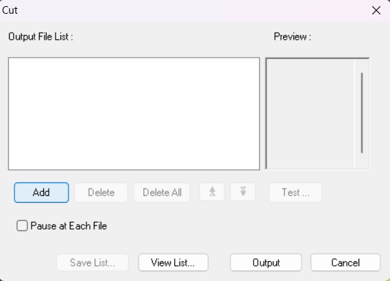
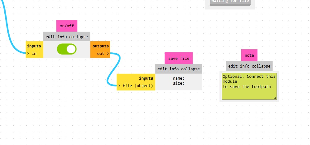
2. Then we have to click on Cut. A window will open, and we should click Add to add our milling code.
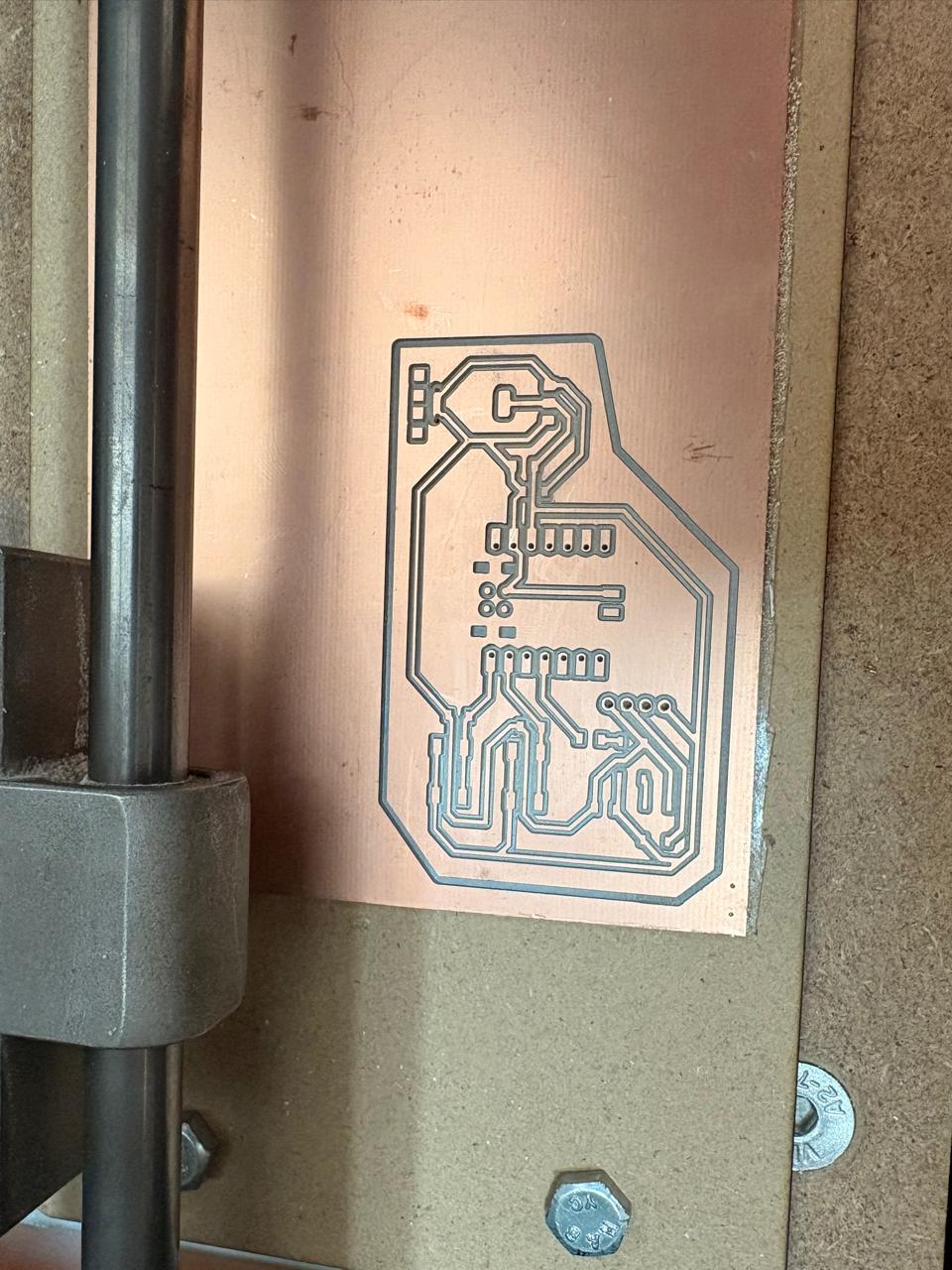
3. Finally we have to click Output and the machine will automatically start to cut.
After Cutting
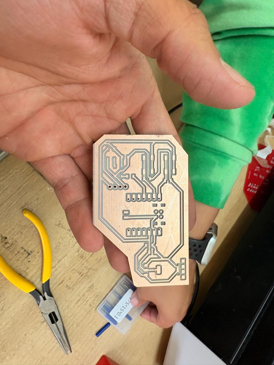
1. After finishing the cutting, very carefully, we must take out the copper board and remove our PCB.
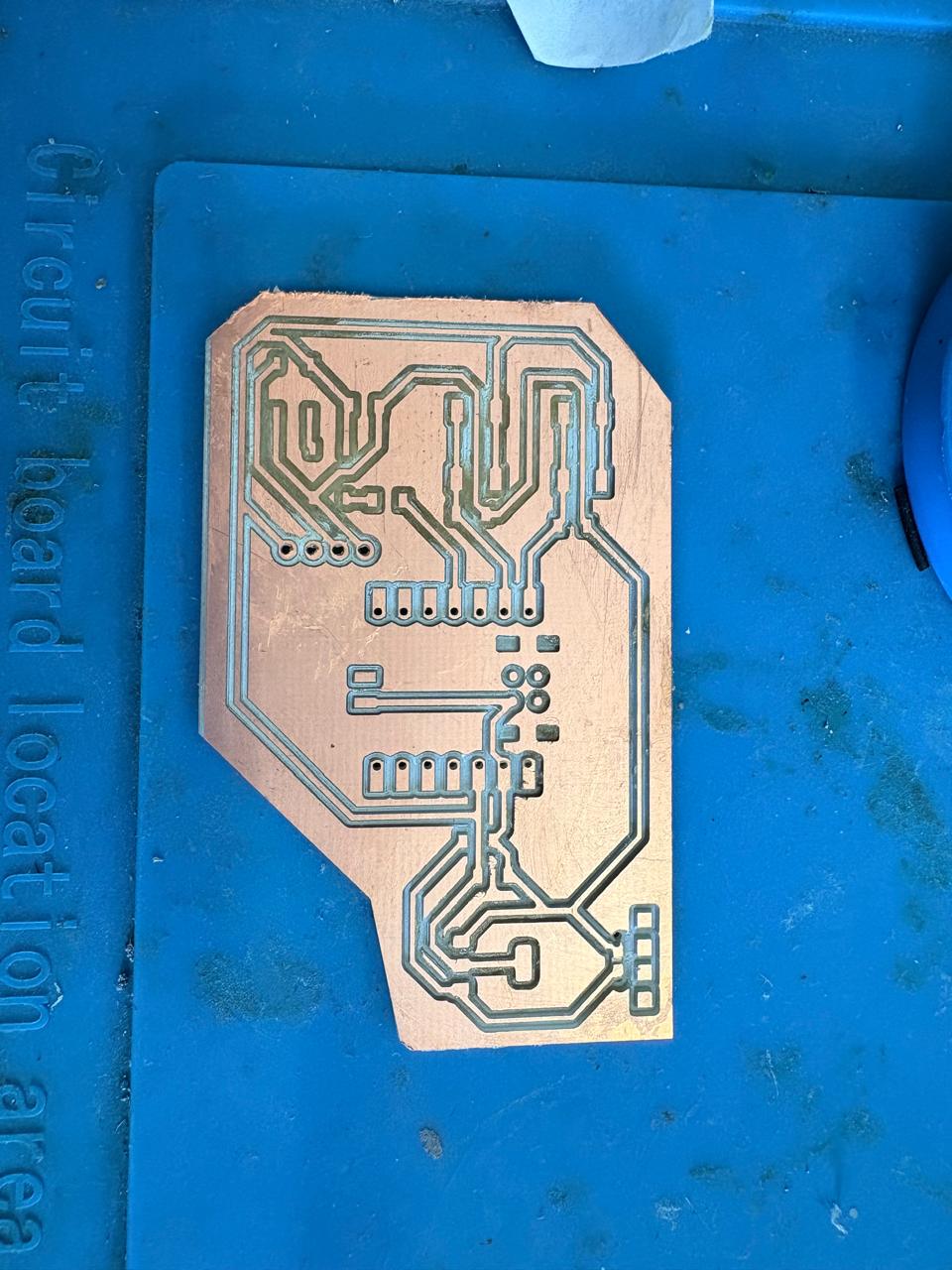
Results
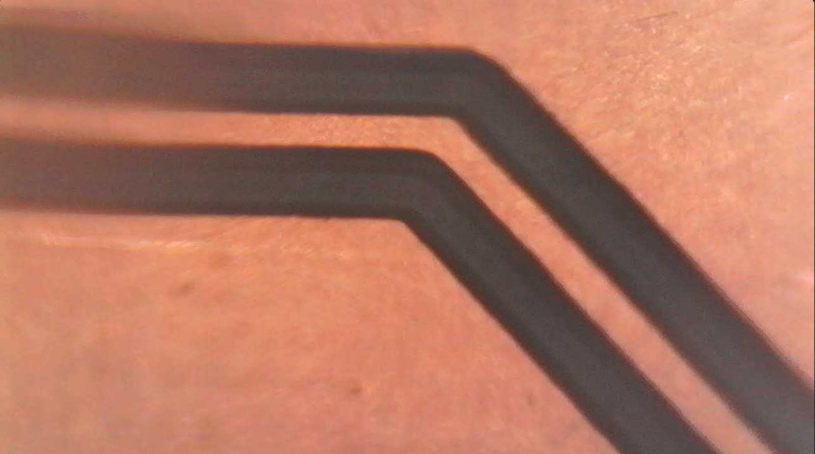
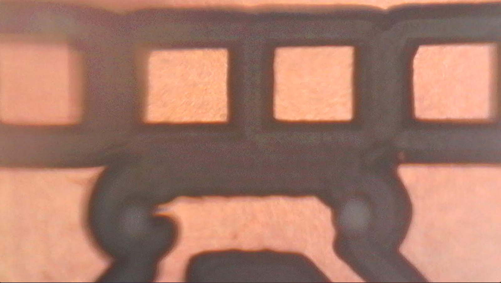
Tracks. They were cut very cleanly, with no burrs or bridges between the tracks.
Micro-USB. Because the micro USB connector is so small, not all of its traces were cut cleanly. However, since I only plan to use it for power, I just need to cut the remaining rectangle in half.
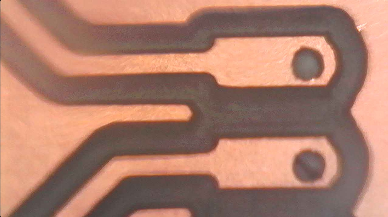
Pads. The pads were cut very cleanly, leaving enough space for soldering.
Soldering
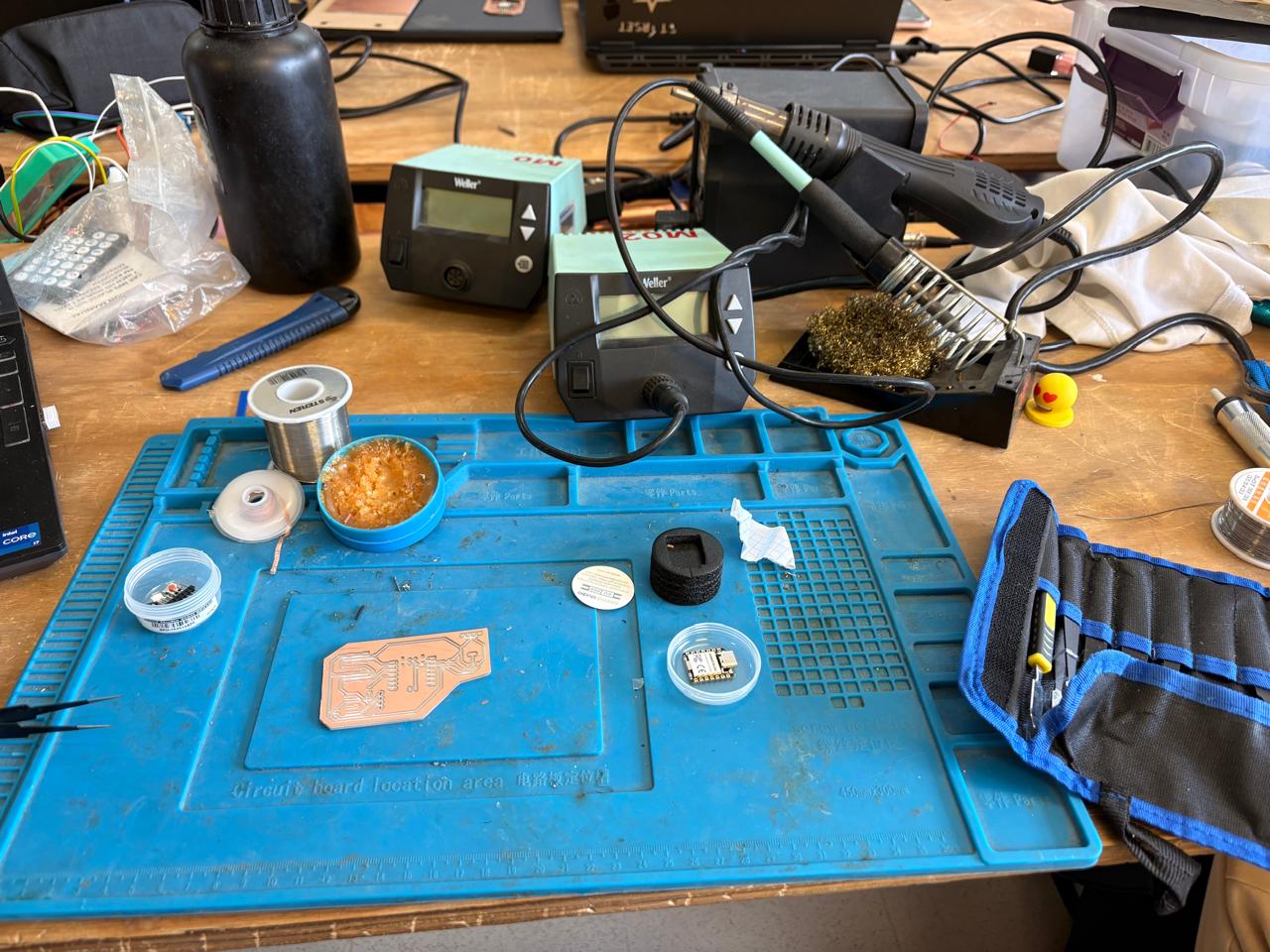
1. To solder, we first need to set up our workspace and gather the necessary tools.
Necessary tools
- Soldering station
- Flux
- Soldering Tin
- Desoldering mesh
- Silicone Tablecloth
Components
- 1 XIAO-RP2350
- 2 smd Buttons
- 2 smd WS2812B
- 1 AMS 1117
Soldering
2. First, we need to apply flux to our PCB so that the solder adheres better.
Soldering
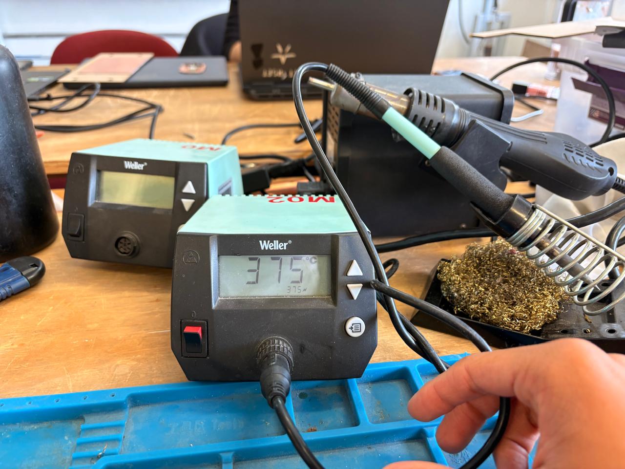
3. Then, we have to turn on the soldering station and set the temperature. To solder tin it is recomendable to place the temperature above 300 °C. I will use 375 °C because that works good with my materials.
Soldering
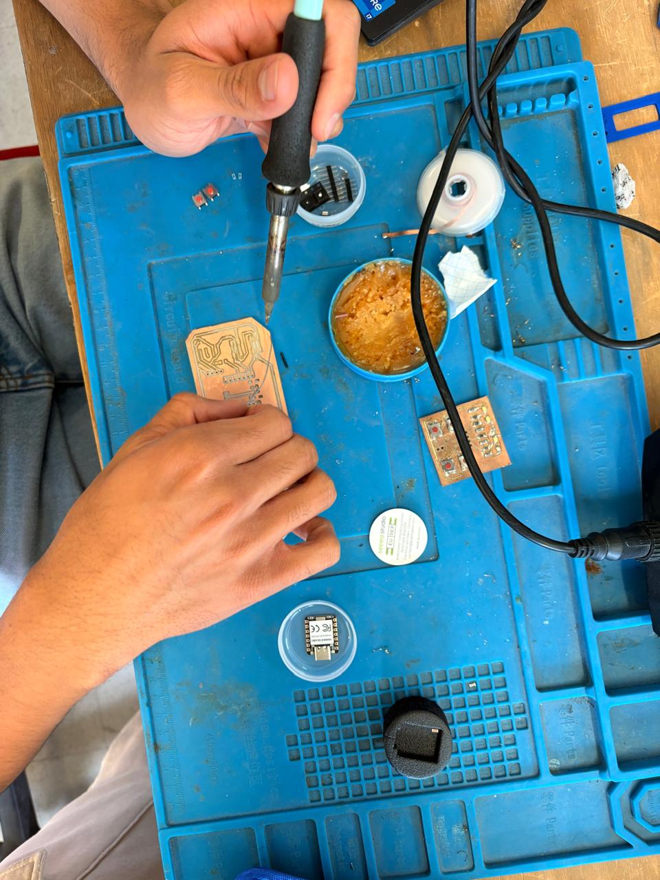
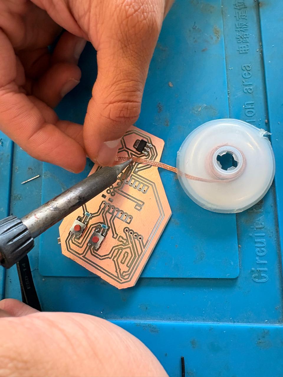
4.To solder, we have to place the soldering iron over the copper board and heat it up, then we have to place the Tin on the surface and wait until it melts. It is important to place the Tin on the copper surfance and not on the soldering iron because the melted Tin flows toward hot surfaces, if we place it on the soldering iron, it won't adhere easily to the copper surface because it will be cooler.
Soldering
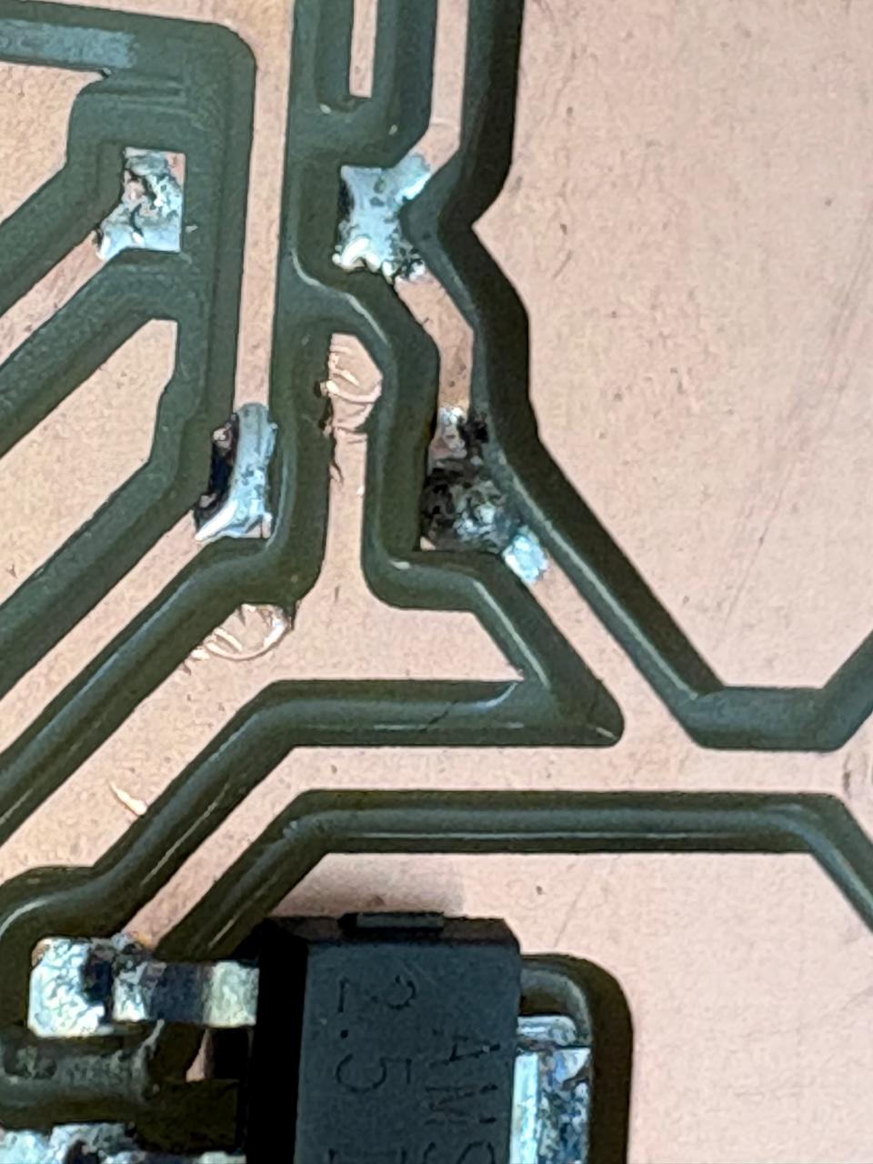
MISTAKE.A common mistake when soldering is applying more solder than necessary; if that happens, there’s no need to worry. To remove the excess solder, place the desoldering braid over the excess, then hold the soldering iron over it to heat it. The braid will absorb the excess solder, and you can then solder as usual.
Results
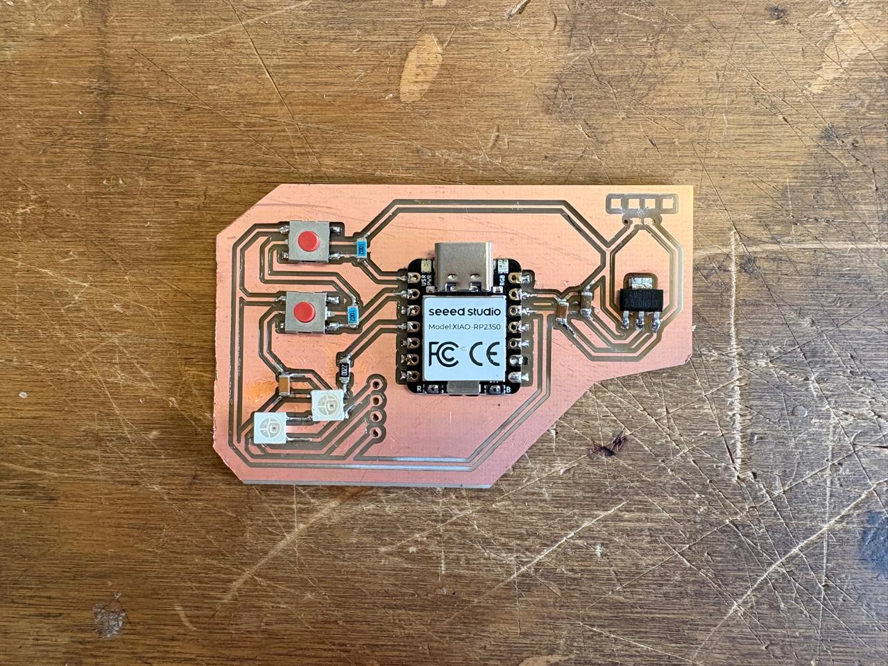
Programming
To code, I used ARDUINO IDE. ARDUINO IDE is a free, open-source application for Windows, macOS, and Linux, used to write, compile, and upload code to Arduino boards. It provides a text editor, toolbar, and serial monitor, supporting C/C++ to create ".ino" sketch files for controlling microcontrollers.

XIAO RP2350 Board
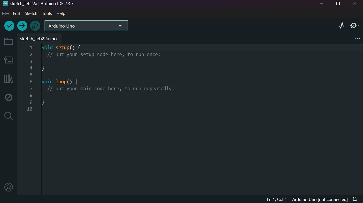
1. First, we have to create a sketch in Arduino IDE.
XIAO RP2350 Board
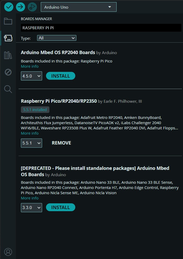
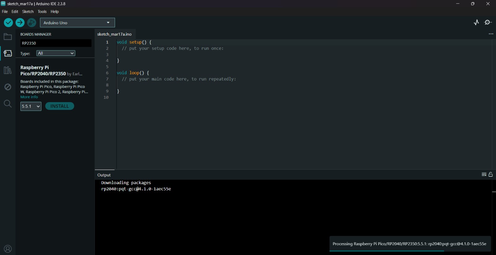
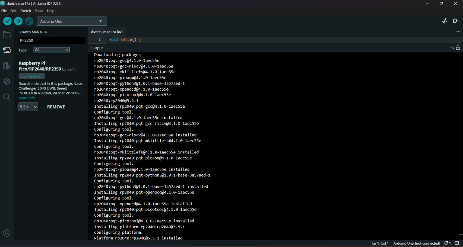
2. Then, we have go to the board manager and write XIAO RP2350. After doing that, a library will appear, its name is Raspberry Pi Pico/RP2040/RP2350 by Earle F. Philhower, III, we must install it.
Uploading
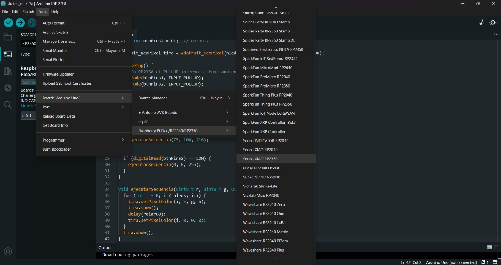
3. After installing the XIAO RP 2350 Board, we must click on the tab that says select board and write Seeed XIAO RP2350, then select the PORT where our microcontroller is connected and upload the information. We can also click Tools, then Board and then the library Raspberry Pi Pico/RP2040/RP2350 by Earle F. Philhower, III and there look for the XIAO. Both ways will let us set our board as a XIAO.
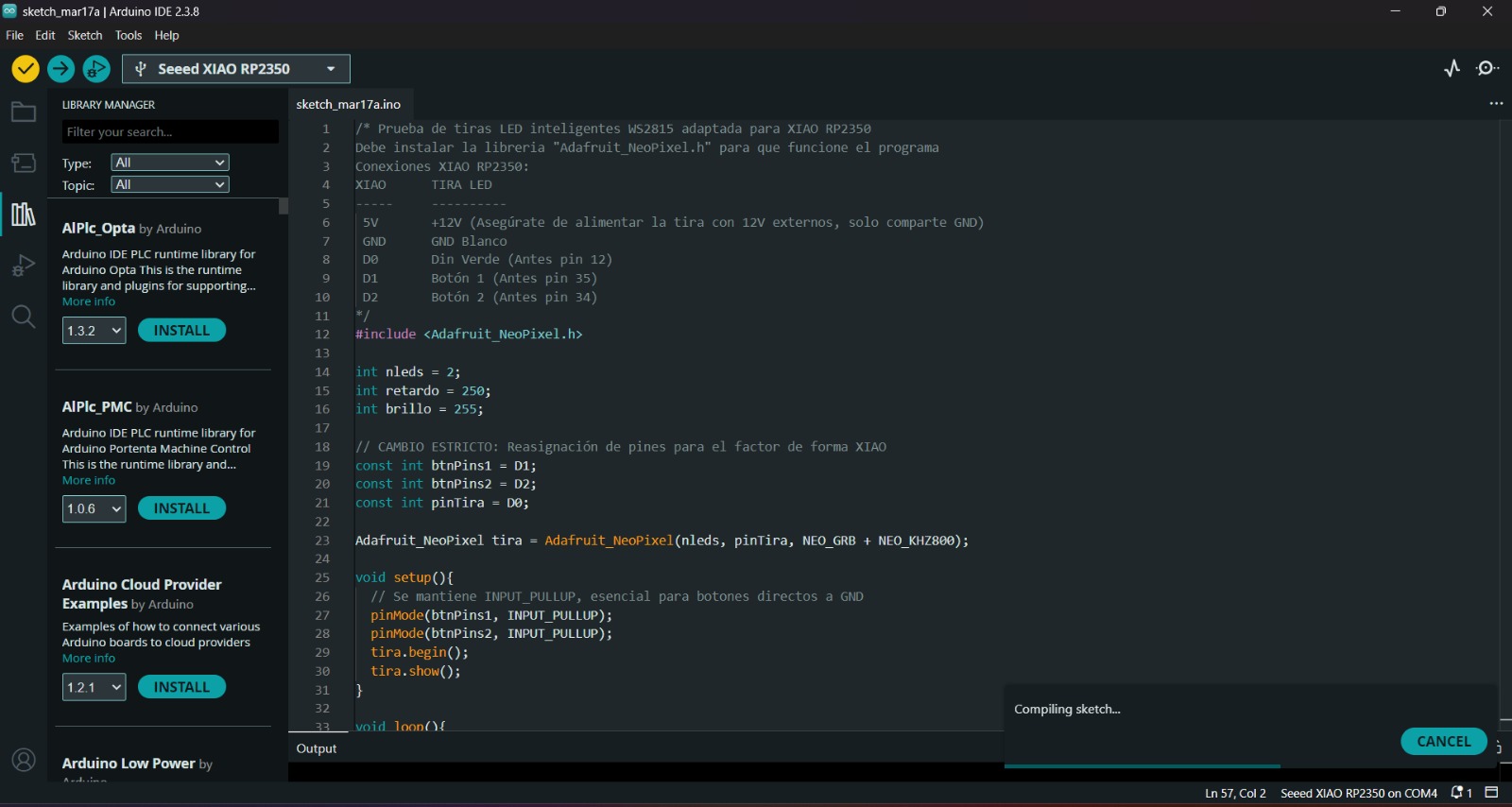
4. Before uploading our code to the microcontroller we should use the verify tool, that compiles the code before uploading it in order to detect mistakes or problems. The verify tool is the one in the top with the check.
5. Finally, to upload our code we must click the upload tool, that is the one with the arrow pointing to the right. If our code is right, it shall compile. To get the , we must click on Tools in the top menu and select Serial Monitor.
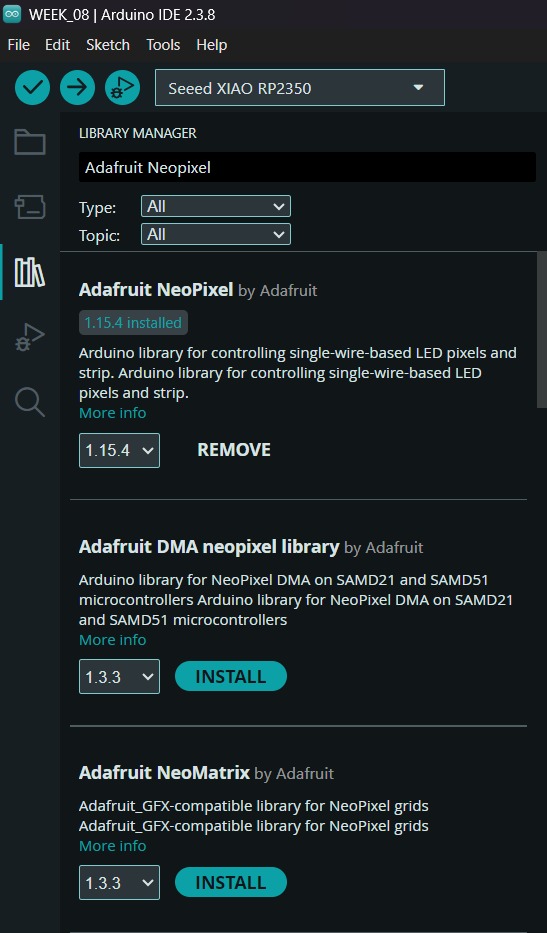
Neopixels Library
To set the neopixels, we first need to install de library in Arduino. For that we have to go to the Library Manager and write Adafruit Neopixel, then intall the library named like that.
Learning outcomes
Since I’m studying mechatronics engineering, I already had some prior exposure to electronics manufacturing; however, this was a wonderful opportunity to see the AMS1117 regulator in action and learn about programming Neopixels, which will be a very useful tool for my project.