FINAL PROJECT
Kamil Gallardo Toledo - FAB ACADEMY
THE KNOCKOUT CONCEPT
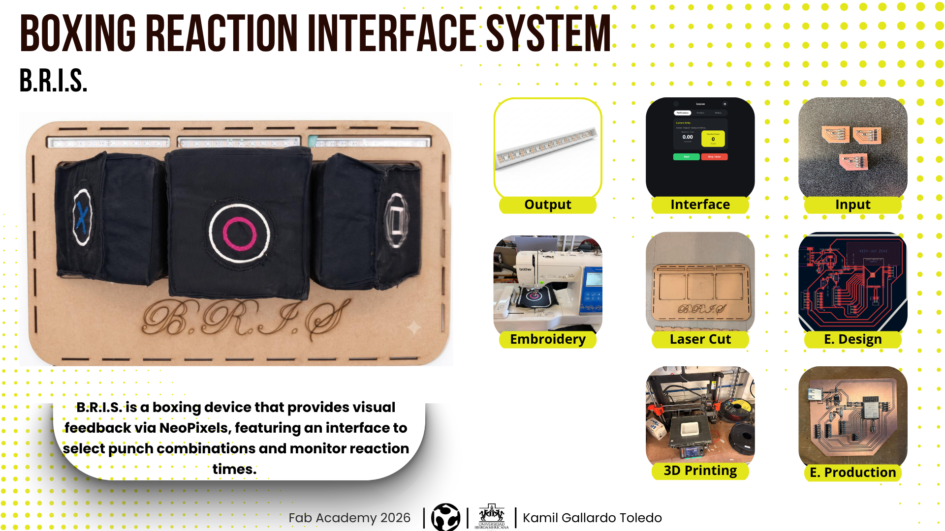
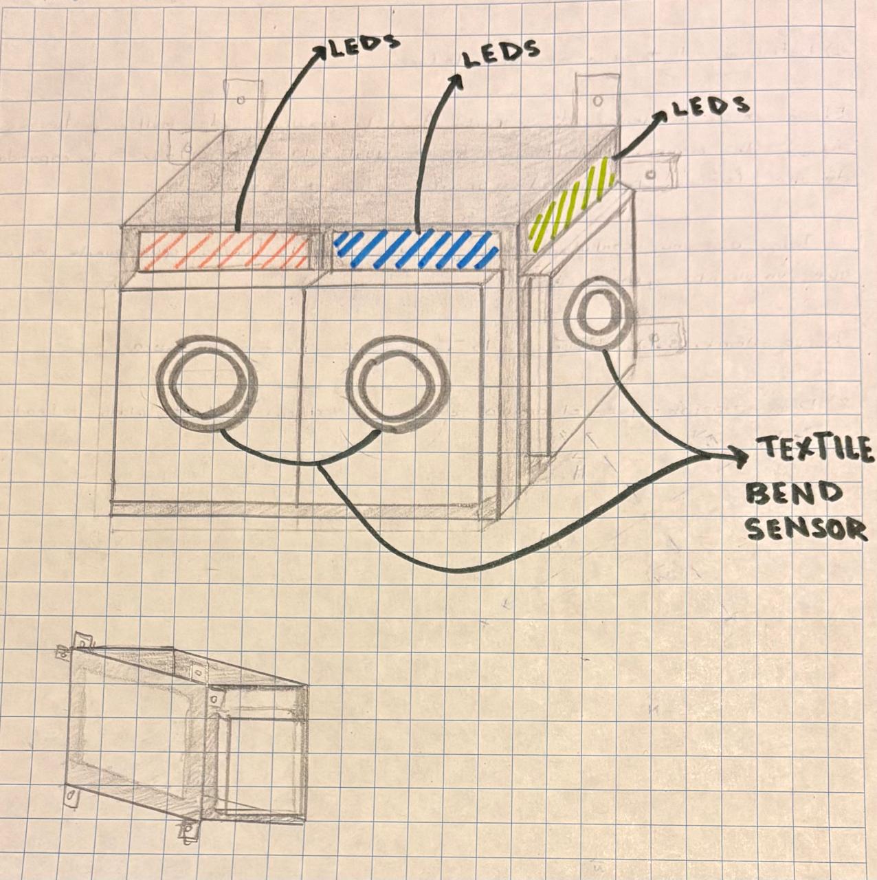
It consists of a device that measures reaction speed and the force of punches for people interested in boxing. Using a visual cue, users can learn punch combinations while receiving feedback through a virtual interface.

WEEK PROGRESS
During some week tasks I tried to learn about some necesarry things for my final project. Here is the progress I have.
COMPONENTS
PCB
| Material | Description | Quantity | Unit price | Source |
|---|---|---|---|---|
| ESP32 WROOM-32 SMD Dual Core 32Bits 4 MB | It is a 32-bit dual-core microcontroller with Wi-Fi and Bluetooth capabilities; it is an SMD surface-mount device with 32 pins. | 1 | $6.46 | UNIT ELECTRONICS |
| AMS1117 3.3v regulator | It is a low-dropout linear voltage regulator. | 1 | - | IBERO |
| 1 USB Type A | It serves as a standard “host” connection to transfer data and power. | 1 | $0.69 | - |
| 10μF smd Capacitors | It is an electronic component that temporarily stores electrical energy in an electric field. | 3 | - | IBERO |
| 100nF smd Capacitors | It is an electronic component that temporarily stores electrical energy in an electric field. | 4 | $1.21 | - |
| 10k Ω resistor | It a passive electrical component that restricts or limits the flow of electrical current in a circuit. | 1 | - | IBERO |
| 2k Ω resistor | It a passive electrical component that restricts or limits the flow of electrical current in a circuit. | 1 | - | IBERO |
| 4.7k Ω resistor | It a passive electrical component that restricts or limits the flow of electrical current in a circuit. | 3 | - | IBERO |
| 0 Ω resistor | It is essentially a wire link packaged to look like a standard resistor. | 1 | - | - |
| 1M Ω resistor | It a passive electrical component that restricts or limits the flow of electrical current in a circuit. | 6 | - | IBERO |
| Blue LED | LED stands for Light-Emitting Diode. It is a highly efficient electronic component made of semiconductor materials that converts electricity directly into light. | 1 | - | IBERO |
| Pinheaders | A pin header is a common electrical connector consisting of one or more rows of metal pins mounted on a plastic base. They are primarily used as bridges on printed circuit boards (PCBs) to route power, data, and signals, or to connect components to external wiring and other boards. | 39 | - | - |
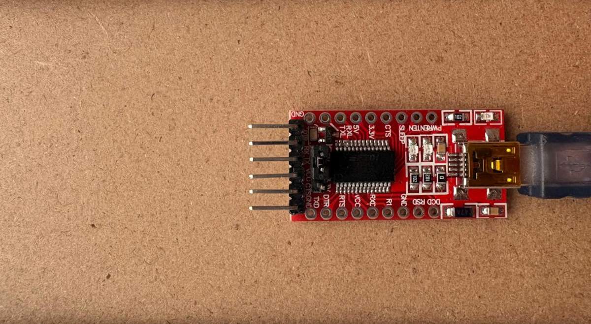
| Ft232rl 3.3v 5v | It is a highly popular USB-to-UART bridge integrated circuit (IC) manufactured by FTDI (Future Technology Devices International). | 1 | $4.55 | Mercado Libre |
| Soku Charger Usb 5v 3a 15w | It is a usb charger. | 1 | $10.21 | Mercado Libre |
| Usb to Usb cable 1.7 meters | It is a usb to usb cable. | 1 | $4.55 | Mercado Libre |
Cases
| Material | Description | Quantity | Unit price | Source |
|---|---|---|---|---|
| PLA | A biodegradable thermoplastic derived from renewable resources like corn starch. It's the standard for desktop printing due to its minimal thermal expansion. | 1 | $20 | Inova Market |
Integration
| Material | Description | Quantity | Unit price | Source |
|---|---|---|---|---|
| 3mm-thick MDF board | MDF (Medium-Density Fiberboard) is an engineered wood product made by breaking down hardwood and softwood residuals into fine fibers, combining them with wax and resin, and pressing them into flat, dense sheets under high heat and pressure. | 2 | $9.51 | HOME DEPOT |
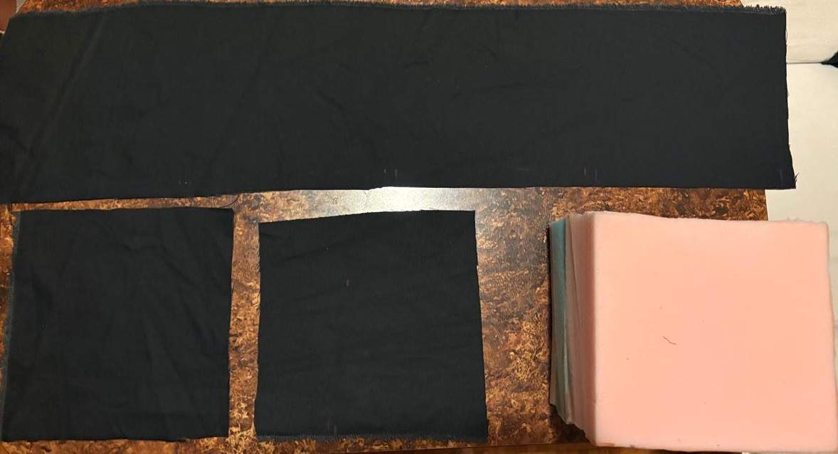
| Canvas fabric snippet | is a highly durable, heavy-duty plain-weave fabric traditionally made from cotton or linen. | 2 | $2.88 | - |
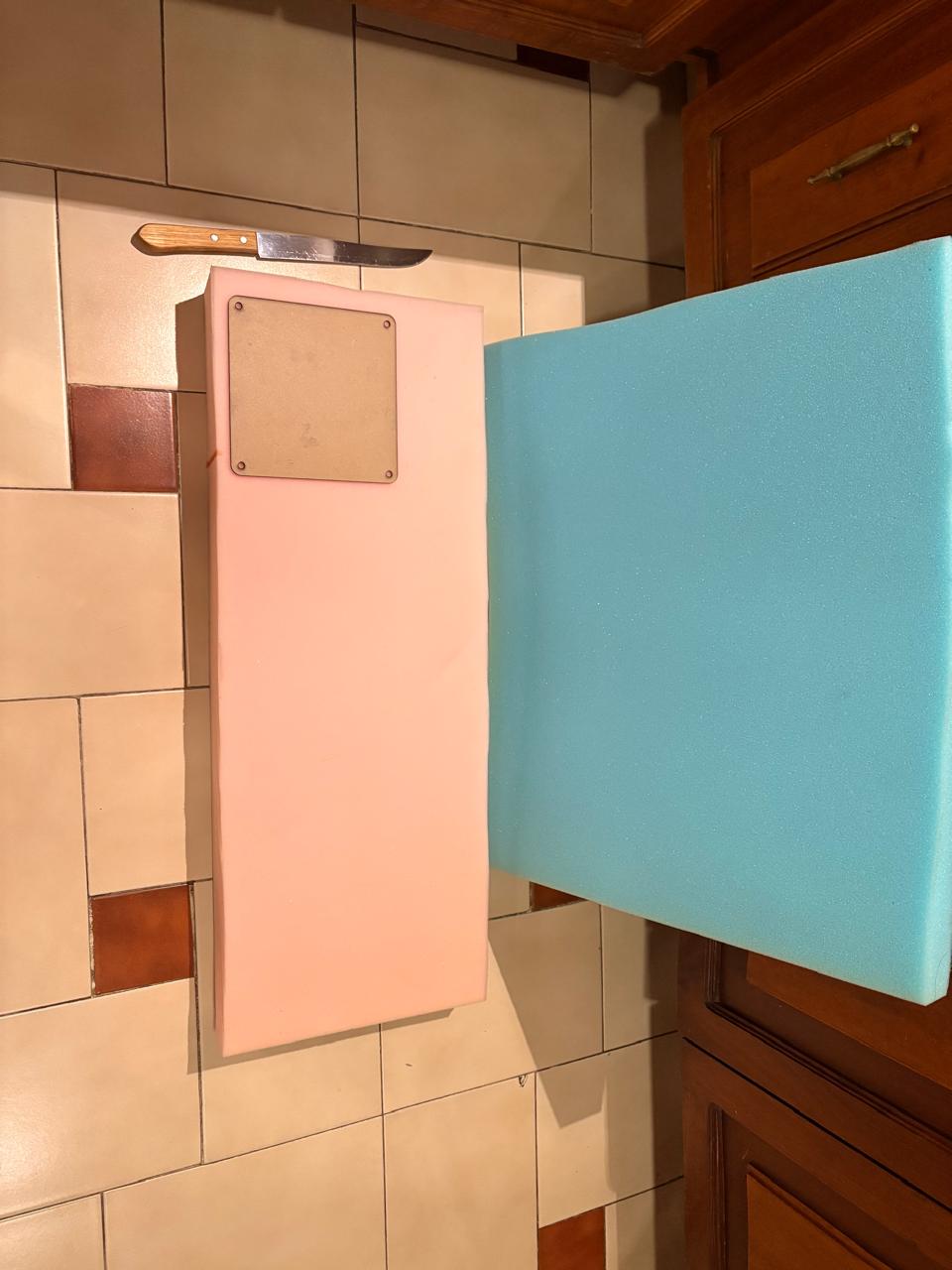
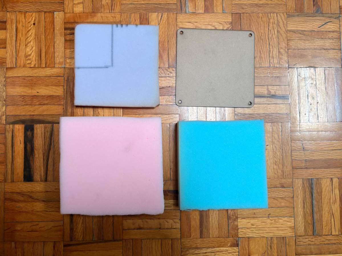
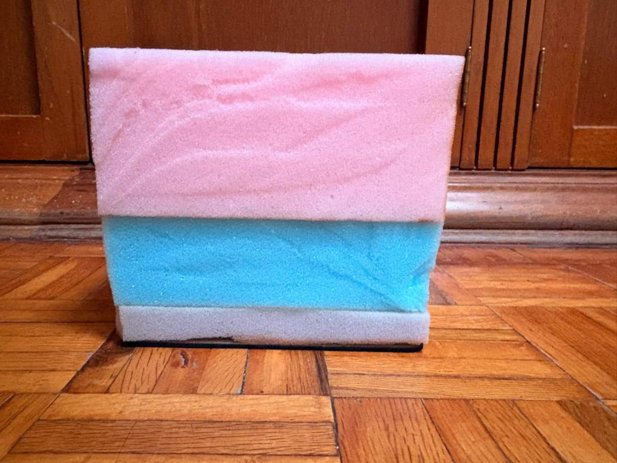
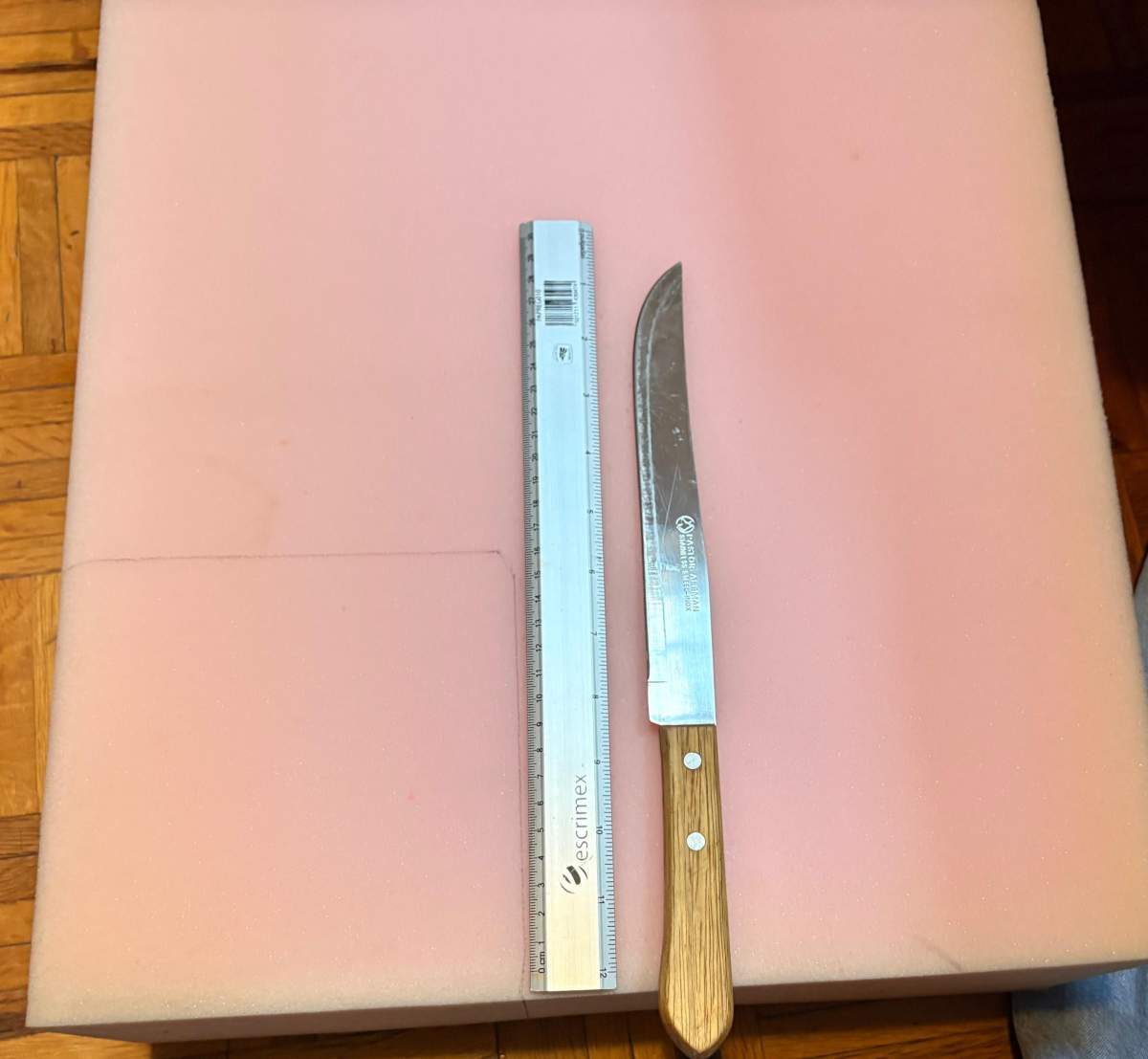
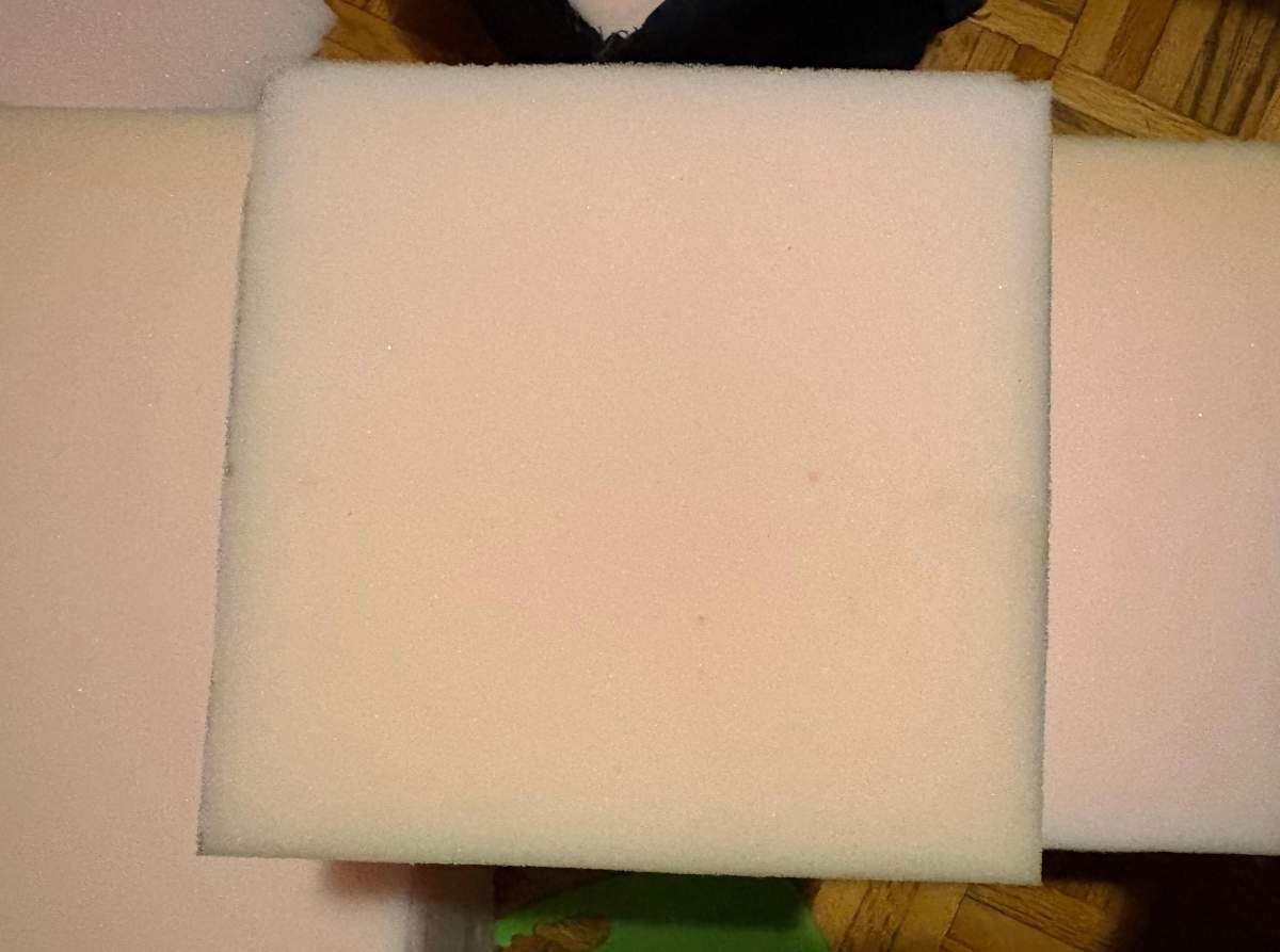
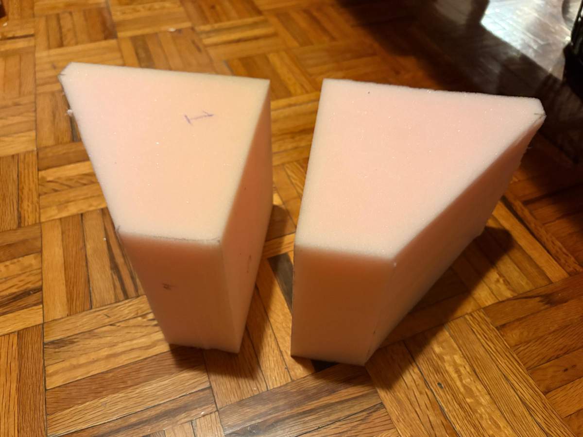
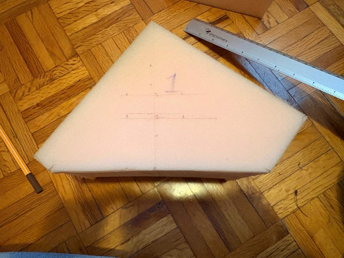
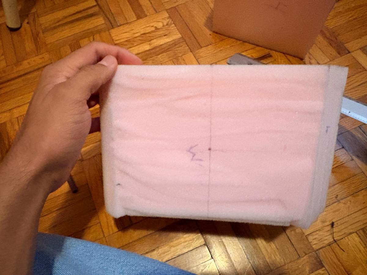
| Foam | These are foams of different densities used for the pads. | 3 | $11.82 | - |
| Adhesive Velcro | These are two strips of Velcro that stick to the wall. | 1 | $8.31 | Amazon |
Boxing Reaction Interface System
Electronic Design & Production
Design
Schematic
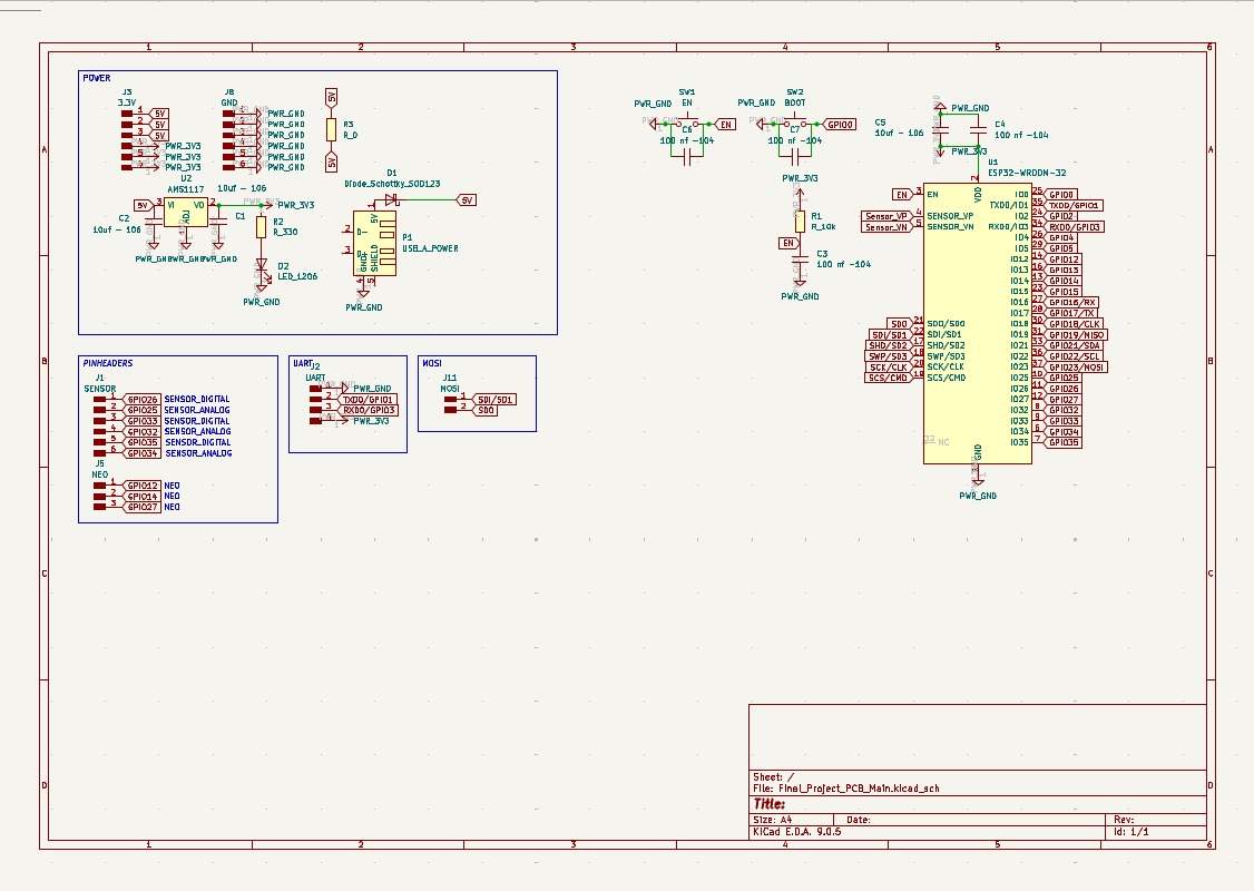
Power
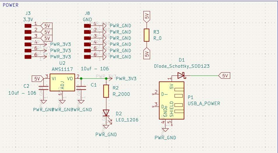
Power
~ To power my circuit, I’ll use a 5V, 3A wall charger, so I connected it to my board via a USB Type-A cable, using only the VCC and GND pins. I intended to use a Schottky diode to protect my circuit; however, my professor Oliver told me that it would significantly reduce my voltage and that the regulator would be sufficient, so I won’t use it when soldering and will instead place a 0-ohm resistor.
Next, I installed an AMS1117 regulator from 5V to 3.3V, placing two 10uF capacitors on the input and output. Then, on the 3.3V output, I placed an LED connected to a 2000Ω resistor to provide a visual indication that it is powering correctly. Finally, I added 3 5V pins and 3 3.3V pins to power my NEOPIXELS and sensors, respectively, and I also added 6 ground pins for the same purpose. The 0-ohm resistor is there to facilitate the connection in the design.
ESP32 WROOM 32
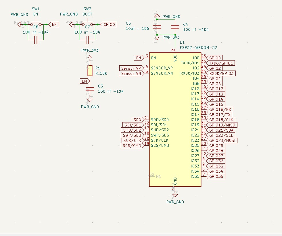
ESP32 WROOM 32
~ The ESP32 WROOM 32 is connected to 3.3V via two capacitors in parallel—one 10uF and the other 100nF—to prevent voltage spikes that could impair the chip's functionality. I installed two buttons, Boot and Enable; both are connected to the ESP32 and to GND via a 100nF capacitors. The capacitor has this value to ensure precise signal transmission. The Enable pin is also connected to a 10k resistor and a 100nF capacitor to GND.
PINS
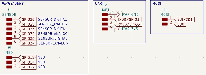
PINS
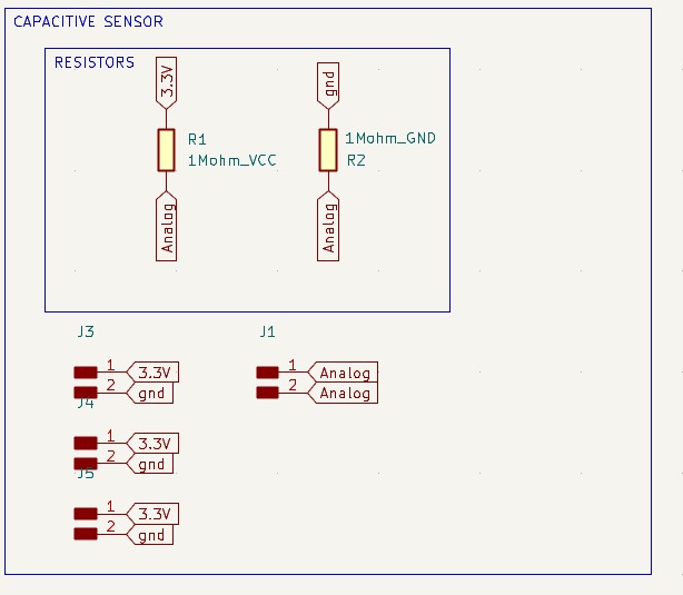
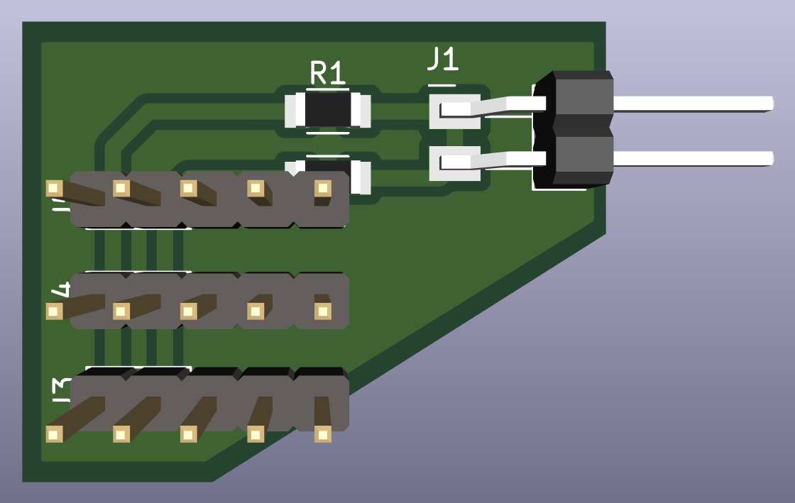
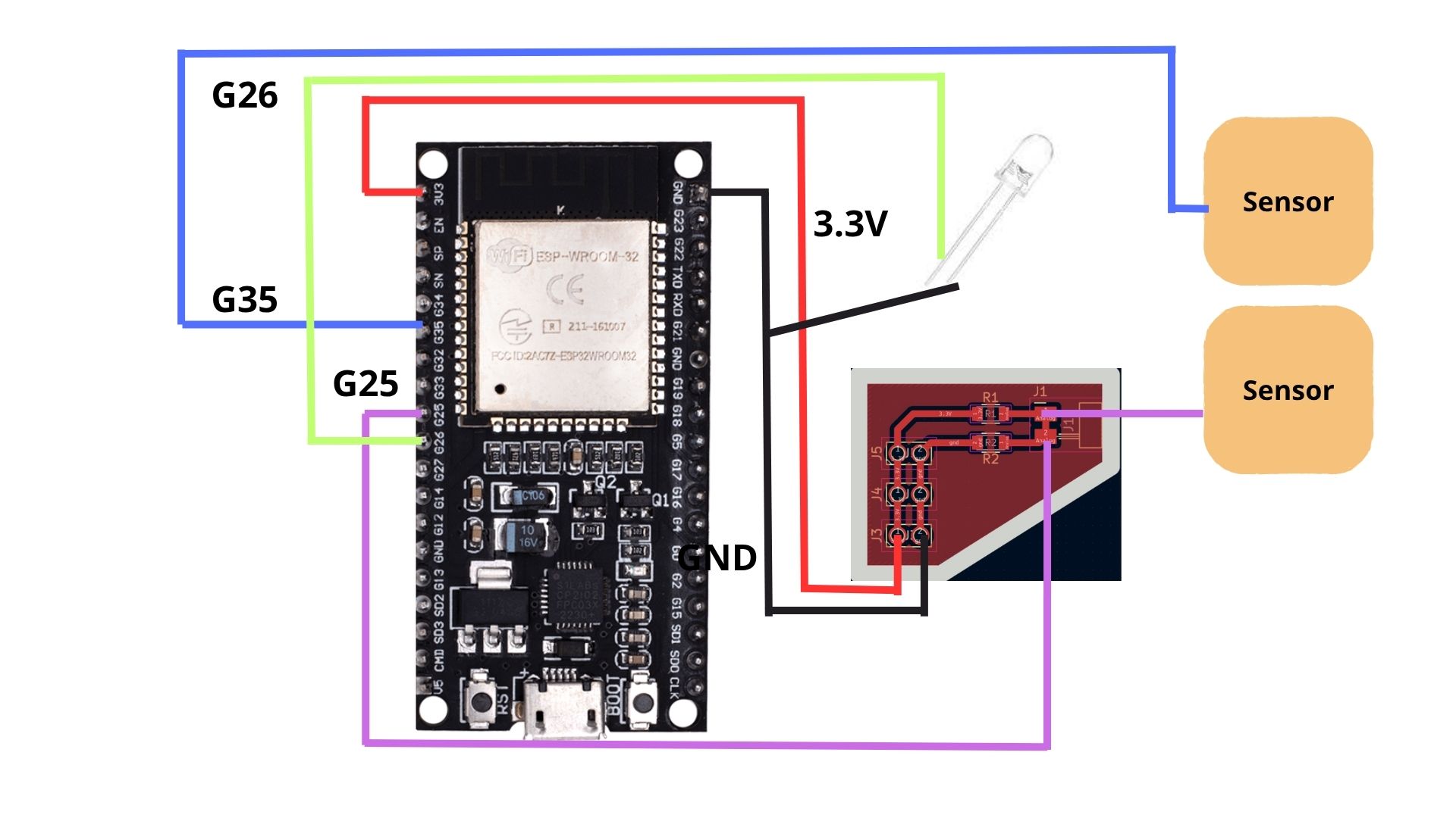
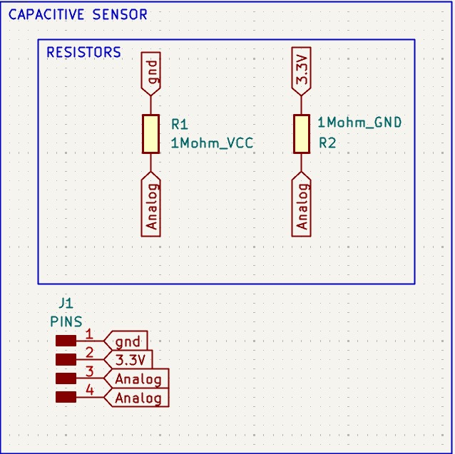
~ The pins are for the three analog sensors, which require four connections (VCC, GND, Input, and Output). Then there are three for the Neopixels (VCC, GND, VIN, VOUT). I also included pins for UART communication so I can program my board, and I left pins for MOSI.
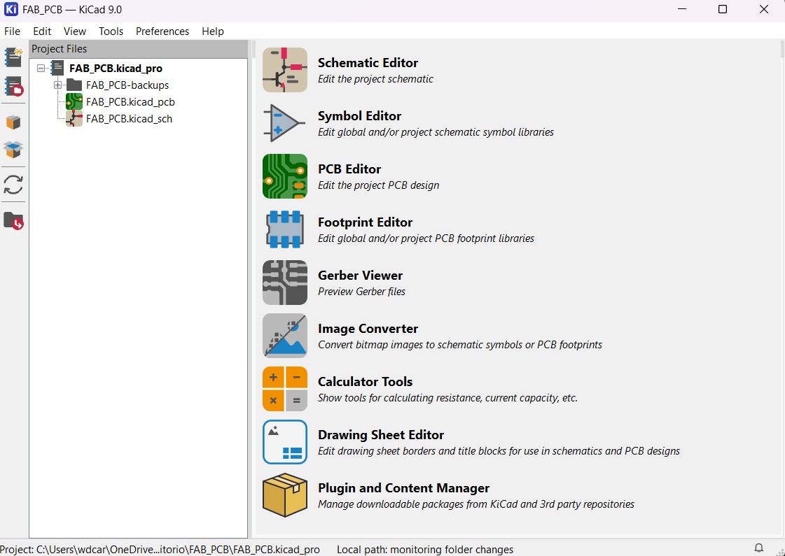
PCB Design
~ Calculator tool. Before defining the size, it is important to calculate it using the calculator tool given by KiCad. To do that we first have to go to the start menu and open the Calculator tool.
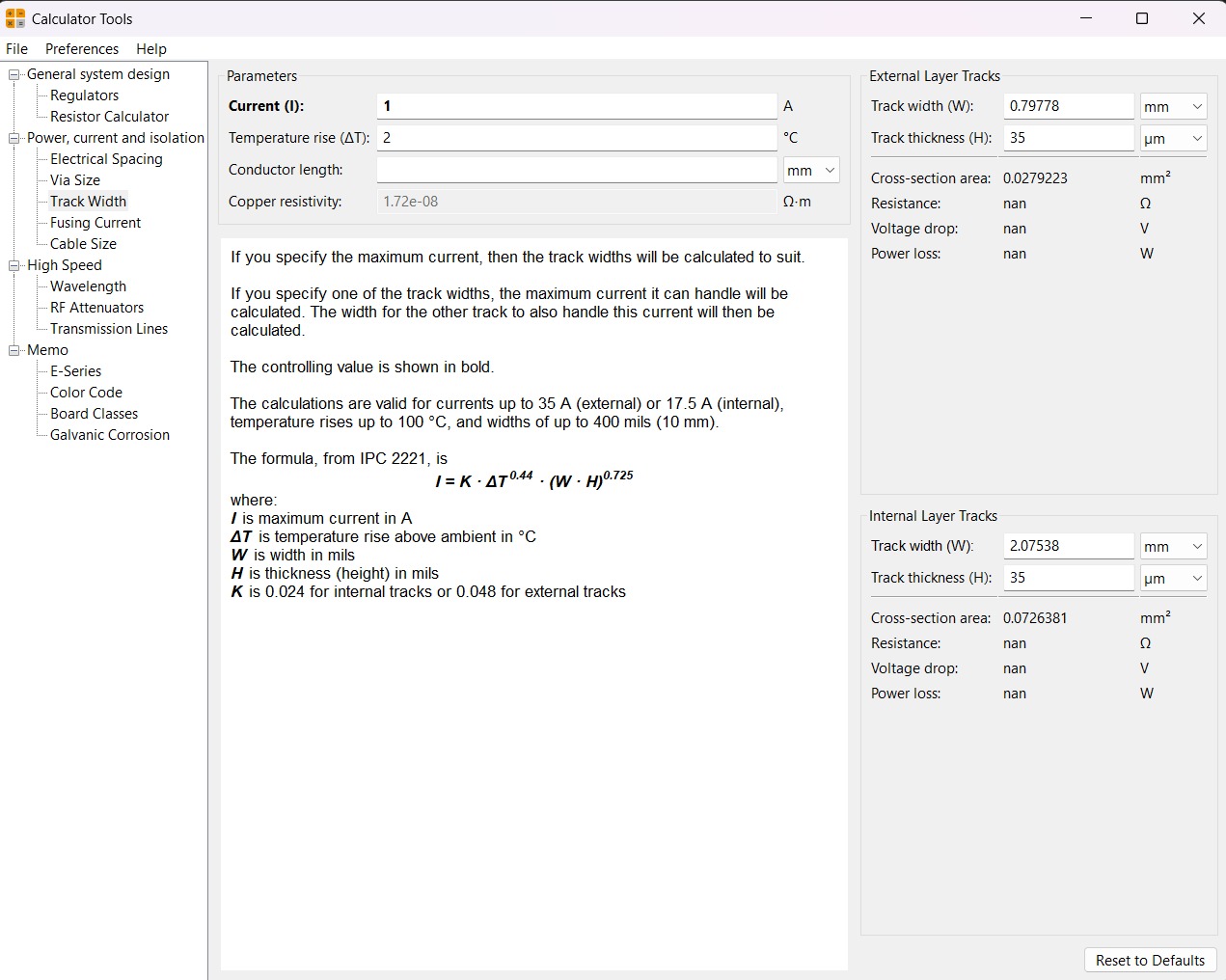
Then add the Current (I) and the Temperature rise we are expecting our PCB to have and look for the result the calculator will give back to us in the right top side. The calculator works by using a formula explained at the bottom.
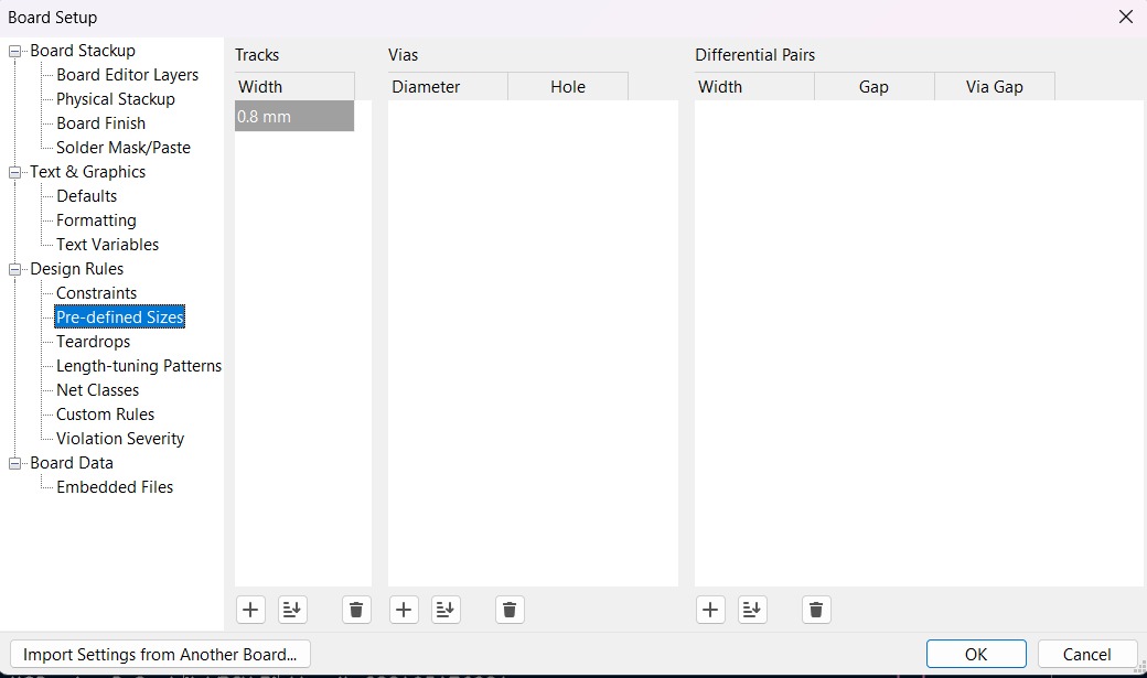
~ Track thickness. To change the track thickness we must go to the top tool section and click on Track use netclass width. Subsequently, select Edit Pre-defined Sizes.
Inside that section we can add tracks sizes by clicking the + symbol located at the bottom of the window, and in the width section we can change the width of the new track we added. Then we'll just have to click Ok.
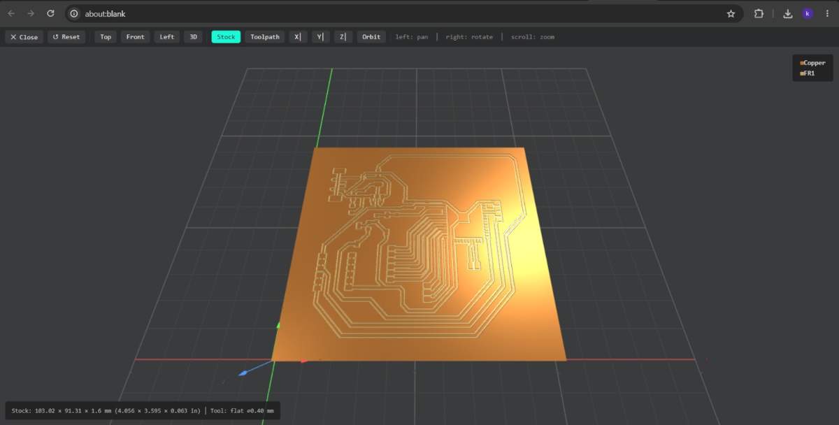
Design
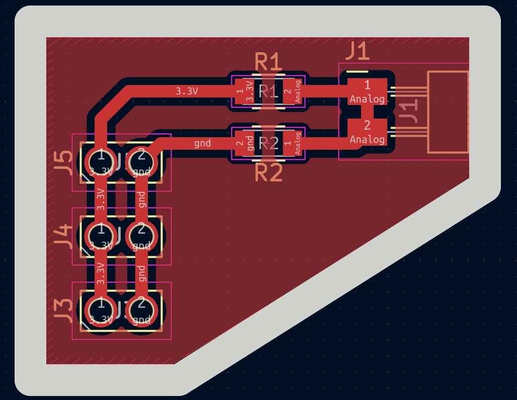
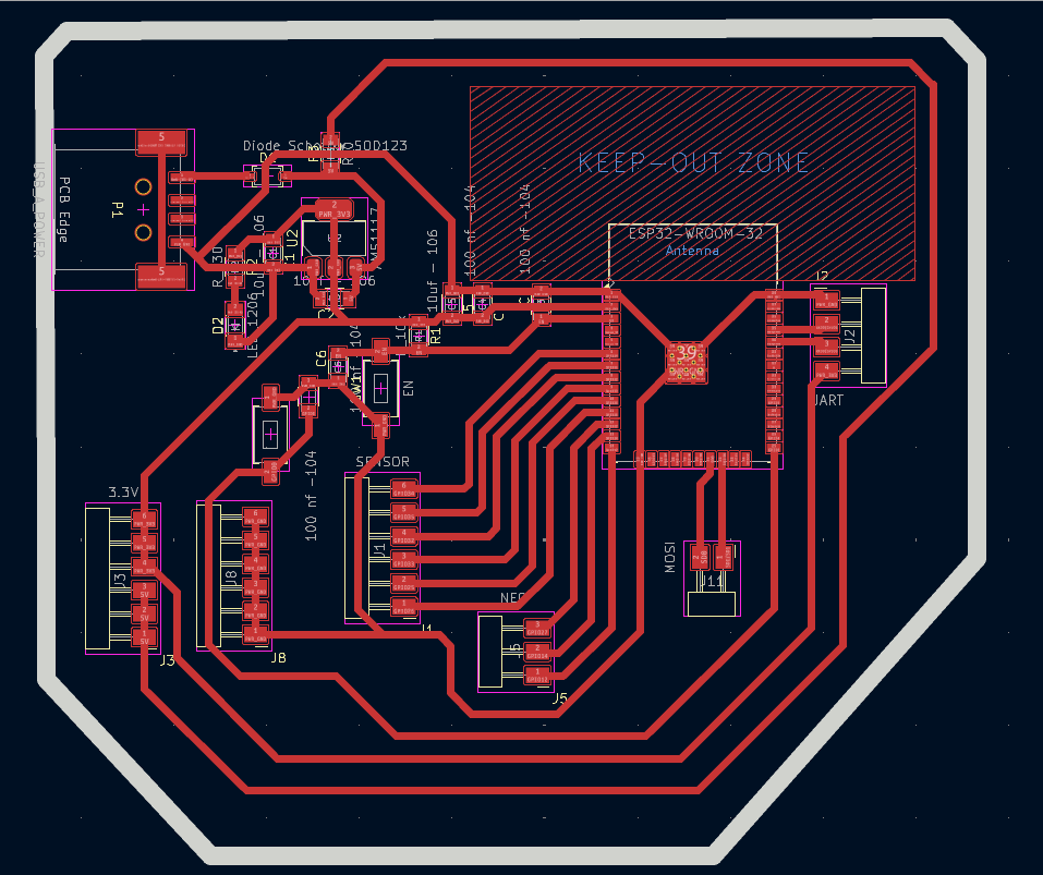
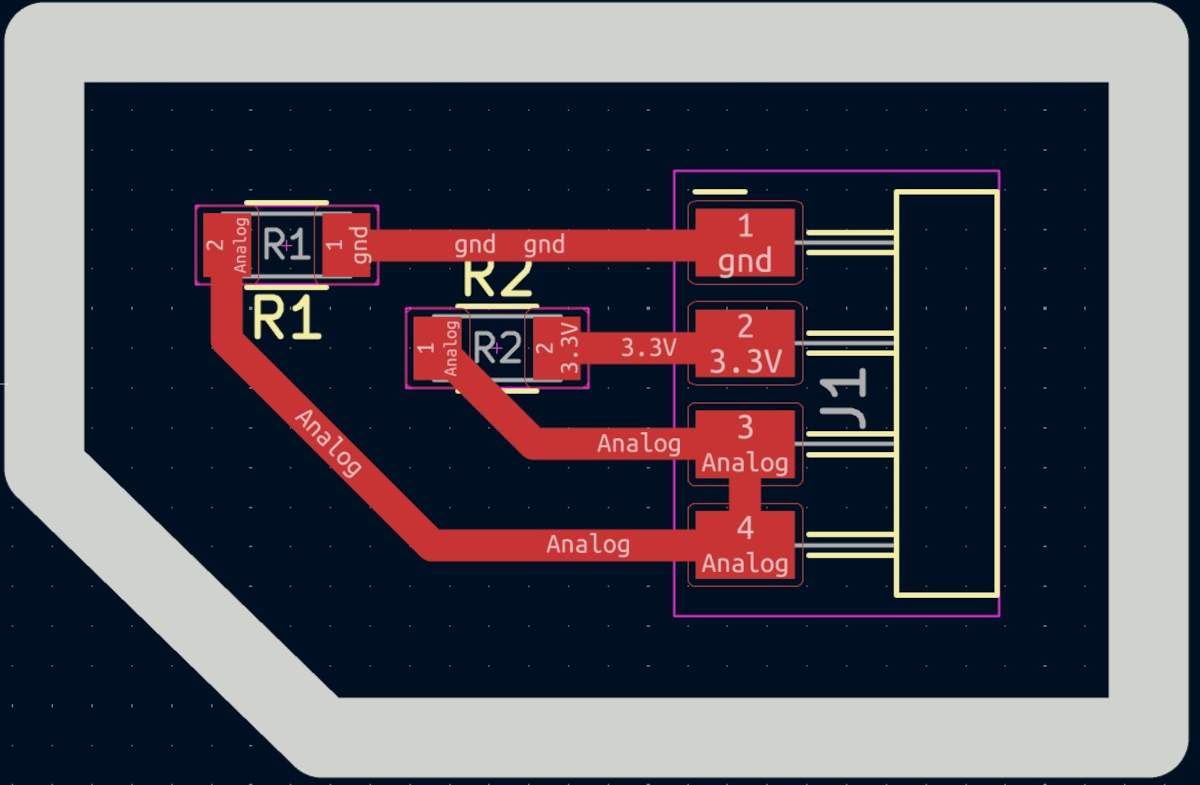
After using KiCad’s width calculation tool, 0.8 mm trace width was selected. I placed the USB at the edge of the board so it would be easier to connect it, then I tried to place all the pins that will be connected to external components as close as posible so I can have more order and I also left the signal space free so it won't be interrfered. The enable and boot buttons are close so I can program it easier.
~ Parameters.
> The outline width is 2 mm and its layer is Edge.Cuts.
> The track’s width is 0.8 mm and its layer is F.Cu.
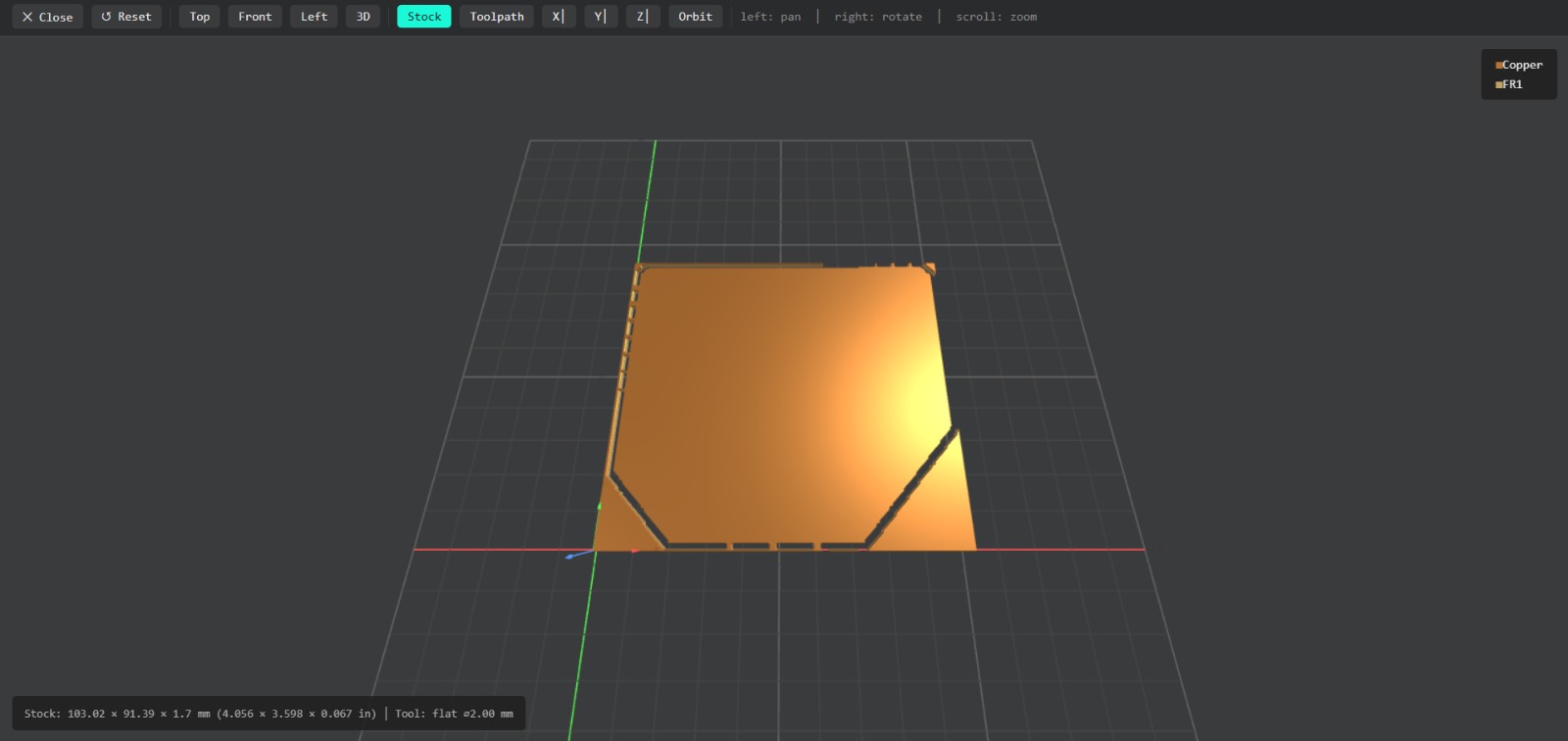
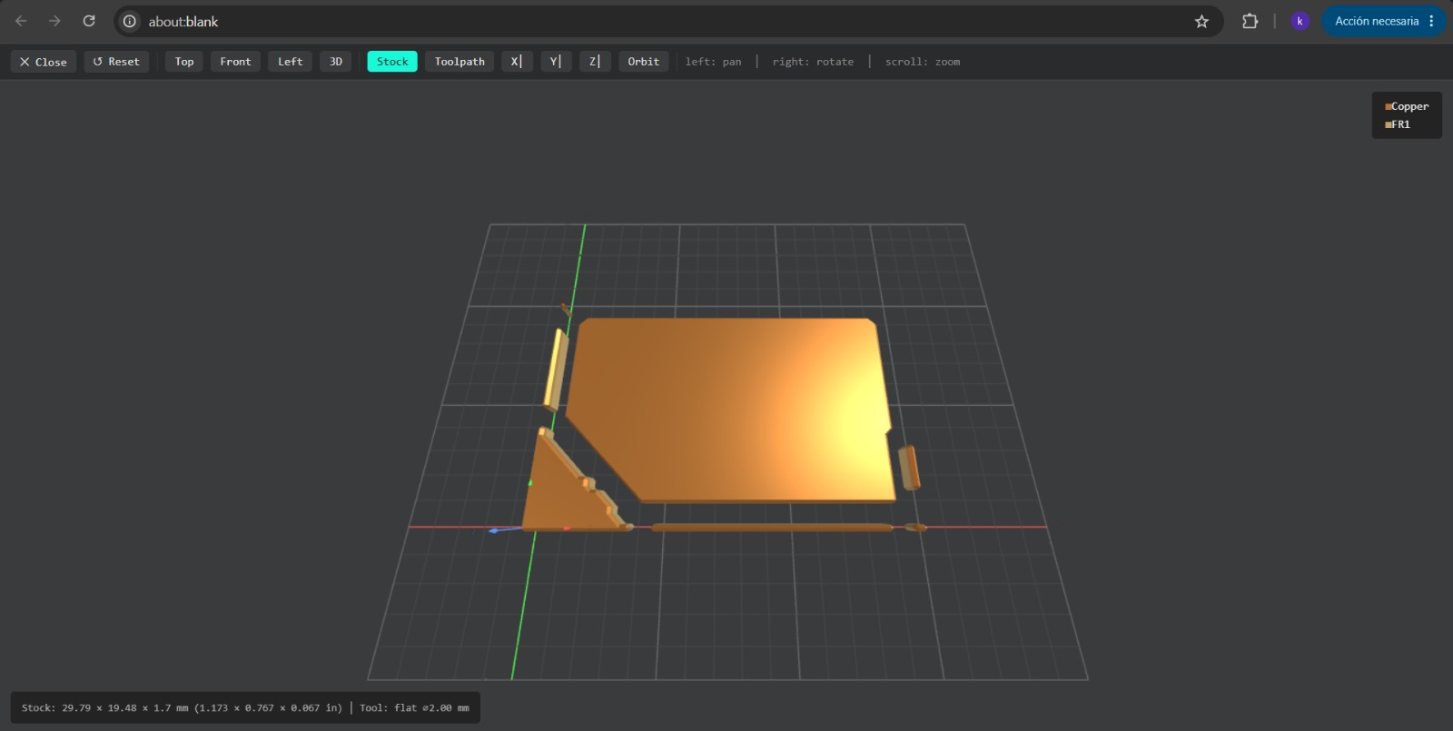
Results
Export as SVG
1. First, I changed the border line width to 2 mm because of the tool that will be used later.
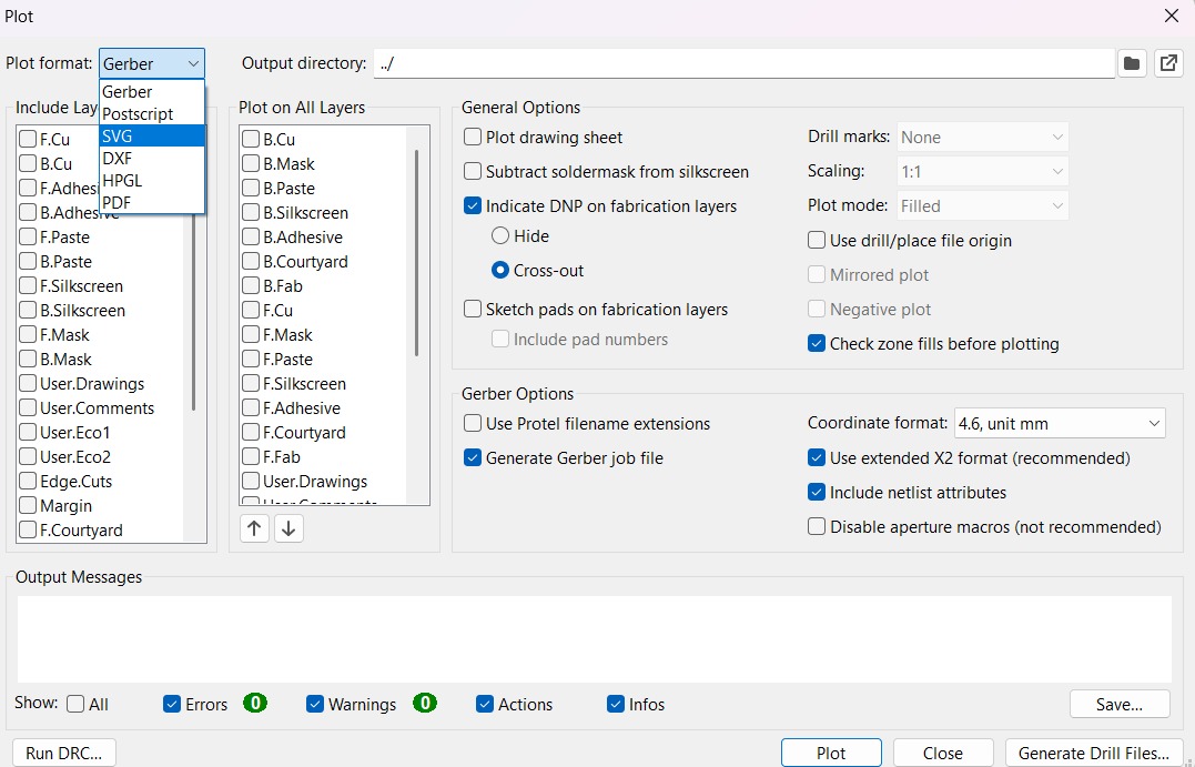
2. Then I went to the top left corner and pressed file, after that I selected Fabrication Outputs.
3. In the fabrication outputs we have to select Gerbers. In Gerbers we have to change the plot format to SVG.
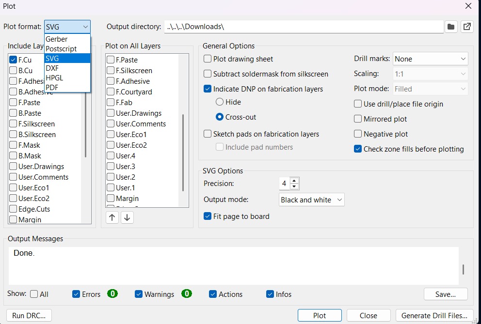
4. Having changed the format to SVG, we have to click on Fit page to board to keep the meassures the way they are in the dessign and select the Output Directory.
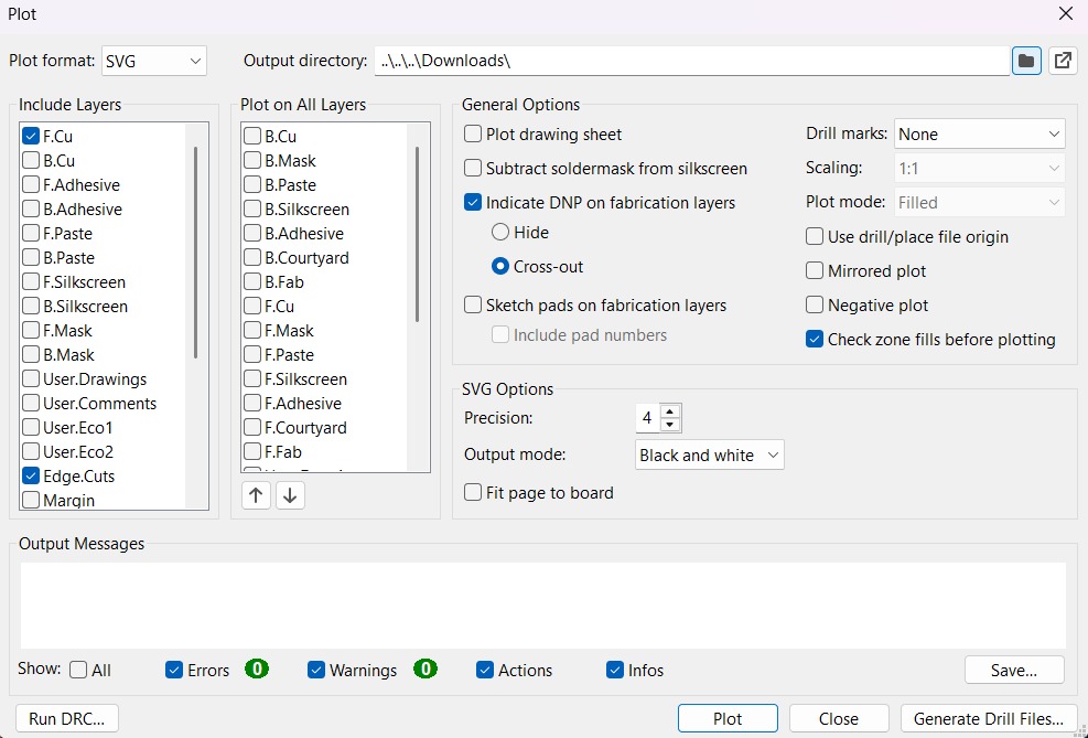
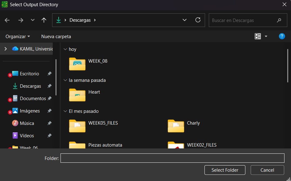
~ Output Directory To change the Output Directory we have to click on the folder symbol located at the top and select the place in our computer where we want to save our document.
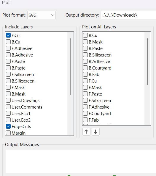
5. Then, we have to select the layers we want to plot.
6. Finally, we have to click on plot and go to the folder where our files are located.
Before Cutting
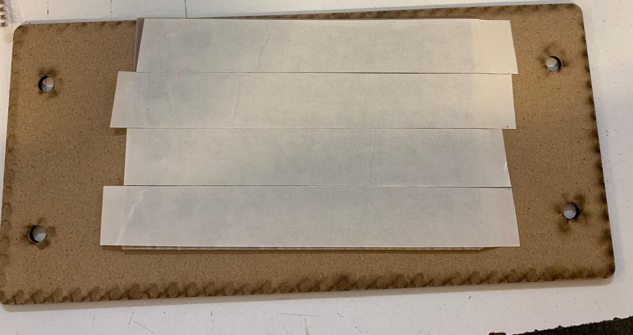
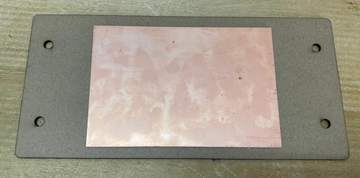
1. First, we have to paste the tape in the back of the copper board.
2. Then, we have to paste the copper board to the Sacrifice Bed.
~ Materials:
> Copper Board.
> Double-sided tape.
> Sacrifice Bed. Is an MDF board designed to prevent the SMR-20 from being damaged in the event that the tool drills too deep.
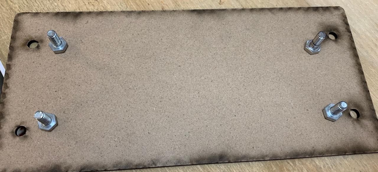
3. Subsequently, we have to place the bed inside the SMR-20. In my case, in my lab, our SMR-20 has a fitting to secure the sacrifice table with screws.
Before Cutting (Tools)
4. Having secured the bed inside the SMR-20, we have to select the tool for each milling process (Tracks and Borders).
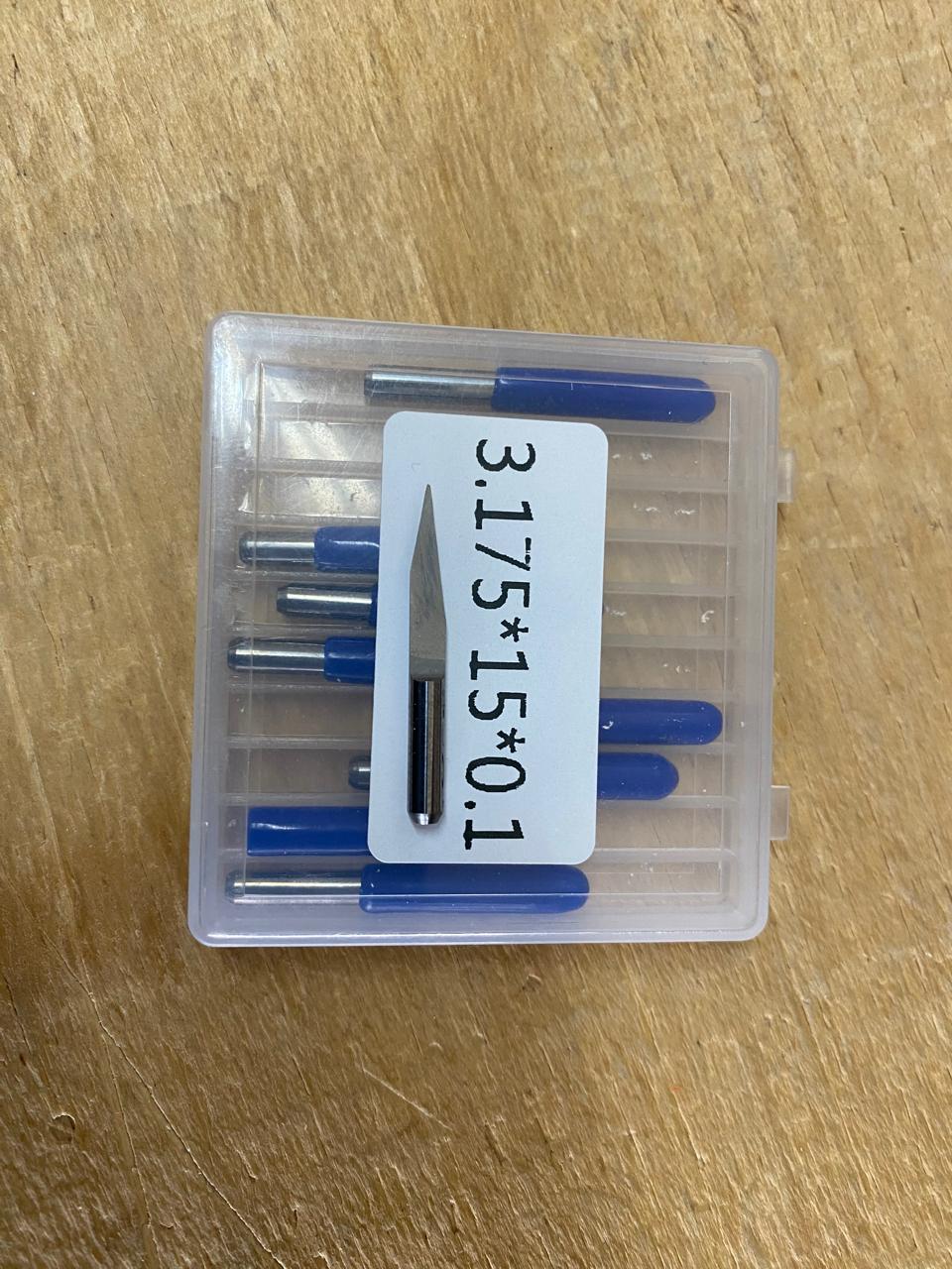
~ Cutting tool. This tool is specifically designed for traces, as its point is sharp and very thin. The Speed of use can be higher but we must be careful about its deep.
~ Cutting - MODS.
> Tool width: 0.39 mm
> Speed: 4 mm/s
> Origin (x,y,z): (0,0,0)
> Offset number: 3
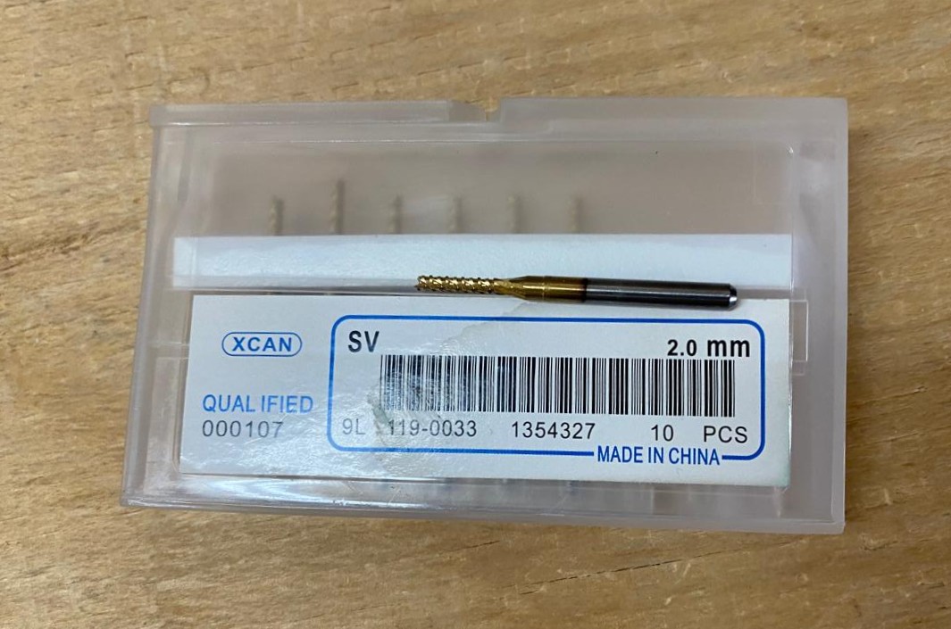
~ Outline tool. This tool is can be used for the border cutting because of its width, it can also be used for perforation, but the diameter of them will be bigger.
~ Outline - MODS.
> Tool width: 2 mm
> Speed: 4 mm/s
> Origin (x,y,z): (0,0,0)
> Offset number: 1
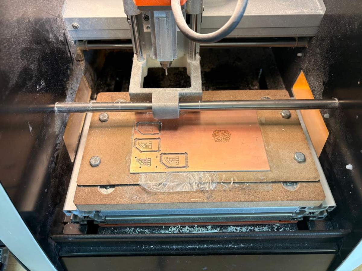
Cutting
1. We have to connect our computer to the SMR-20 and open VPANEL.
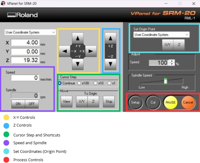
~ VPANEL Overview:
> X-Y Controls: Move the tool in the X-Y axis.
> Z Controls: Move the tool in the Z axis.
> Cursor Step and Shortcuts: The Step Cursor determines the speed at which the tool moves along all axes; Continue is the smoothest and x1 is the slowest setting, since each click corresponds to a single motor movement. The Shortcuts are to automatically move to an already saved point (Origin Point).
> Speed and Spindle: Is to set the speed and to turn on or turn off the the spin of the tool.
> Set Coordinates (Origin Point): By clicking the XY or the Z button we can set the Origin Point.
> Process Controls: Cut is for adding our code and start the process. Pause allows you to pause the process and resume it from where it left off. Stop stops the process.
Cutting Setup
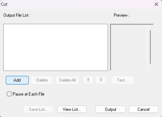
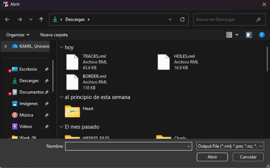
2. Then we have to click on Cut. A window will open, and we should click Add to add our milling code.
3. Finally we have to click Output and the machine will automatically start to cut.
After Cutting
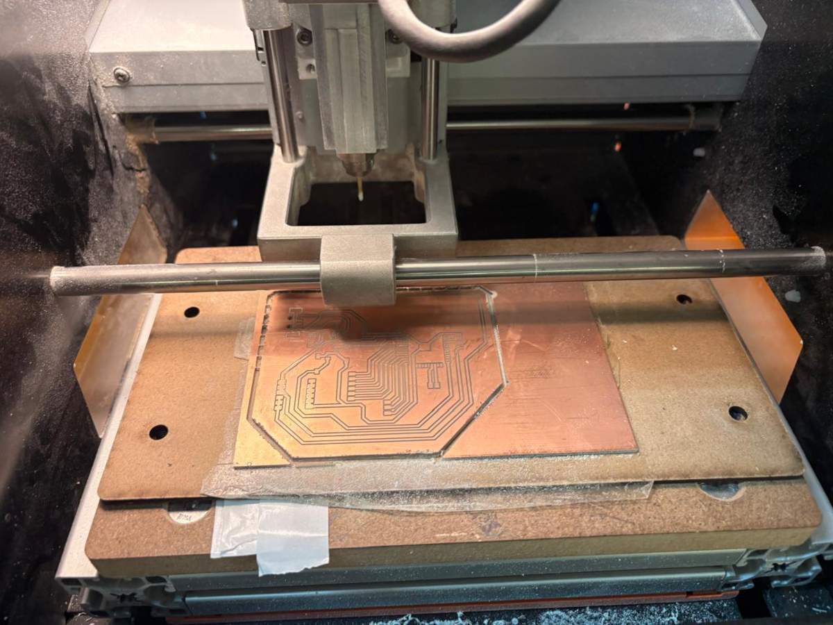
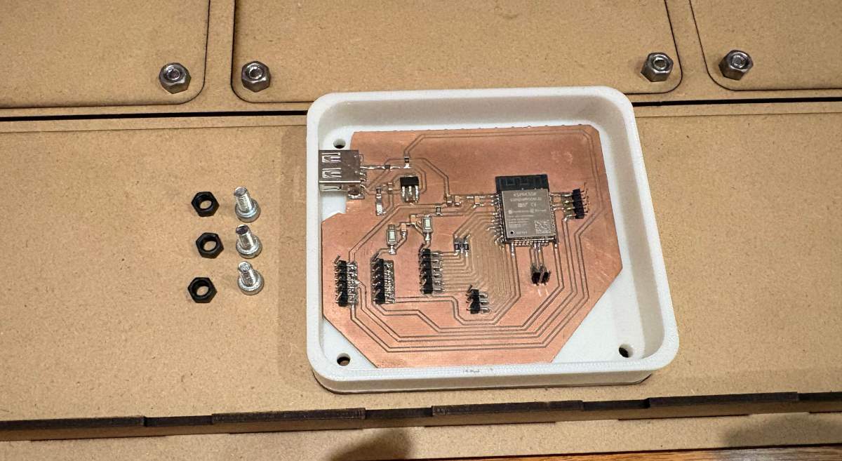
1. After finishing the cutting, very carefully, we must take out the copper board and remove our PCB.
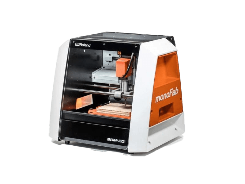
Roland SRM-20
Design
Schematic
Power
Power
~ To power my circuit, I’ll use a 5V, 3A wall charger, so I connected it to my board via a USB Type-A cable, using only the VCC and GND pins. I intended to use a Schottky diode to protect my circuit; however, my professor Oliver told me that it would significantly reduce my voltage and that the regulator would be sufficient, so I won’t use it when soldering and will instead place a 0-ohm resistor.
Next, I installed an AMS1117 regulator from 5V to 3.3V, placing two 10uF capacitors on the input and output. Then, on the 3.3V output, I placed an LED connected to a 2000Ω resistor to provide a visual indication that it is powering correctly. Finally, I added 3 5V pins and 3 3.3V pins to power my NEOPIXELS and sensors, respectively, and I also added 6 ground pins for the same purpose. The 0-ohm resistor is there to facilitate the connection in the design.
ESP32 WROOM 32
ESP32 WROOM 32
~ The ESP32 WROOM 32 is connected to 3.3V via two capacitors in parallel—one 10uF and the other 100nF—to prevent voltage spikes that could impair the chip's functionality. I installed two buttons, Boot and Enable; both are connected to the ESP32 and to GND via a 100nF capacitors. The capacitor has this value to ensure precise signal transmission. The Enable pin is also connected to a 10k resistor and a 100nF capacitor to GND.
PINS
PINS
~ The pins are for the three analog sensors, which require four connections (VCC, GND, Input, and Output). Then there are three for the Neopixels (VCC, GND, VIN, VOUT). I also included pins for UART communication so I can program my board, and I left pins for MOSI.
PCB Design
~ Calculator tool. Before defining the size, it is important to calculate it using the calculator tool given by KiCad. To do that we first have to go to the start menu and open the Calculator tool.
Then add the Current (I) and the Temperature rise we are expecting our PCB to have and look for the result the calculator will give back to us in the right top side. The calculator works by using a formula explained at the bottom.
~ Track thickness. To change the track thickness we must go to the top tool section and click on Track use netclass width. Subsequently, select Edit Pre-defined Sizes.
Inside that section we can add tracks sizes by clicking the + symbol located at the bottom of the window, and in the width section we can change the width of the new track we added. Then we'll just have to click Ok.
Design
After using KiCad’s width calculation tool, 0.8 mm trace width was selected. I placed the USB at the edge of the board so it would be easier to connect it, then I tried to place all the pins that will be connected to external components as close as posible so I can have more order and I also left the signal space free so it won't be interrfered. The enable and boot buttons are close so I can program it easier.
~ Parameters.
> The outline width is 2 mm and its layer is Edge.Cuts.
> The track’s width is 0.8 mm and its layer is F.Cu.
Results
Export as SVG
1. First, I changed the border line width to 2 mm because of the tool that will be used later.
2. Then I went to the top left corner and pressed file, after that I selected Fabrication Outputs.
3. In the fabrication outputs we have to select Gerbers. In Gerbers we have to change the plot format to SVG.
4. Having changed the format to SVG, we have to click on Fit page to board to keep the meassures the way they are in the dessign and select the Output Directory.
~ Output Directory To change the Output Directory we have to click on the folder symbol located at the top and select the place in our computer where we want to save our document.
5. Then, we have to select the layers we want to plot.
6. Finally, we have to click on plot and go to the folder where our files are located.
Before Cutting
1. First, we have to paste the tape in the back of the copper board.
2. Then, we have to paste the copper board to the Sacrifice Bed.
~ Materials:
> Copper Board.
> Double-sided tape.
> Sacrifice Bed. Is an MDF board designed to prevent the SMR-20 from being damaged in the event that the tool drills too deep.
3. Subsequently, we have to place the bed inside the SMR-20. In my case, in my lab, our SMR-20 has a fitting to secure the sacrifice table with screws.
Before Cutting (Tools)
4. Having secured the bed inside the SMR-20, we have to select the tool for each milling process (Tracks and Borders).
~ Cutting tool. This tool is specifically designed for traces, as its point is sharp and very thin. The Speed of use can be higher but we must be careful about its deep.
~ Cutting - MODS.
> Tool width: 0.39 mm
> Speed: 4 mm/s
> Origin (x,y,z): (0,0,0)
> Offset number: 3
~ Outline tool. This tool is can be used for the border cutting because of its width, it can also be used for perforation, but the diameter of them will be bigger.
~ Outline - MODS.
> Tool width: 2 mm
> Speed: 4 mm/s
> Origin (x,y,z): (0,0,0)
> Offset number: 1
Cutting
1. We have to connect our computer to the SMR-20 and open VPANEL.
~ VPANEL Overview:
> X-Y Controls: Move the tool in the X-Y axis.
> Z Controls: Move the tool in the Z axis.
> Cursor Step and Shortcuts: The Step Cursor determines the speed at which the tool moves along all axes; Continue is the smoothest and x1 is the slowest setting, since each click corresponds to a single motor movement. The Shortcuts are to automatically move to an already saved point (Origin Point).
> Speed and Spindle: Is to set the speed and to turn on or turn off the the spin of the tool.
> Set Coordinates (Origin Point): By clicking the XY or the Z button we can set the Origin Point.
> Process Controls: Cut is for adding our code and start the process. Pause allows you to pause the process and resume it from where it left off. Stop stops the process.
Cutting Setup
2. Then we have to click on Cut. A window will open, and we should click Add to add our milling code.
3. Finally we have to click Output and the machine will automatically start to cut.
After Cutting
1. After finishing the cutting, very carefully, we must take out the copper board and remove our PCB.
The tool used for cutting the boards is the Roland SRM-20. Is a compact CNC desktop milling machine used for prototyping, PCB milling, and small mechanical parts. It removes material using rotating cutting tools.
> Work area: 203.2 × 152.4 × 60.5 mm
> Table size: 232.2 × 156.6 mm
> Spindle speed: 3,000 – 7,000 rpm
> Feed rate: 6 – 1800 mm/min
> Mechanical resolution: ~0.000998 mm/step
> Max workpiece weight: 2 kg
> Control interface: USB (RML-1 or NC code)
Soldering
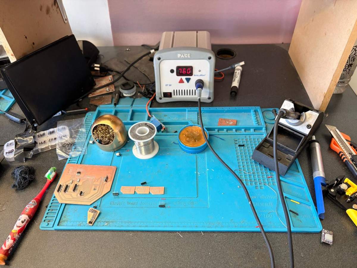
1. To solder, we first need to set up our workspace and gather the necessary tools.
~ Necessary tools:
- Soldering station
- Flux
- Soldering Tin
- Desoldering mesh
- Silicone Tablecloth
~ Components:
- Pinheaders
- 3 10μF smd Capacitors
- 4 100nF smd Capacitors
- 1 AMS1117
- 1 USB TYPE A
- 39 Pinheaders
- 1 ESP32 WROOM 32
- 2 Buttons
- 2 0Ω resistors
- 1 10kΩ resistor
- 1 2kΩ resistor
- 6 1MΩ resistors
- 1 LED
Soldering
2. First, we need to apply flux to our PCB so that the solder adheres better.
3. Then, we have to turn on the soldering station and set the temperature. To solder tin it is recomendable to place the temperature above 300 °C (572 °F). I will use 404 °C (760 °F) because that works good with my materials.
4. To solder, we have to place the soldering iron over the copper board and heat it up, then we have to place the Tin on the surface and wait until it melts. It is important to place the Tin on the copper surface and not on the soldering iron because the melted Tin flows toward hot surfaces. If we place it on the soldering iron, it won't adhere easily to the copper surface because it will be cooler.
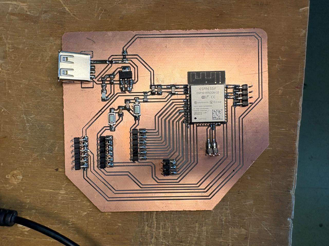
Results
Main board
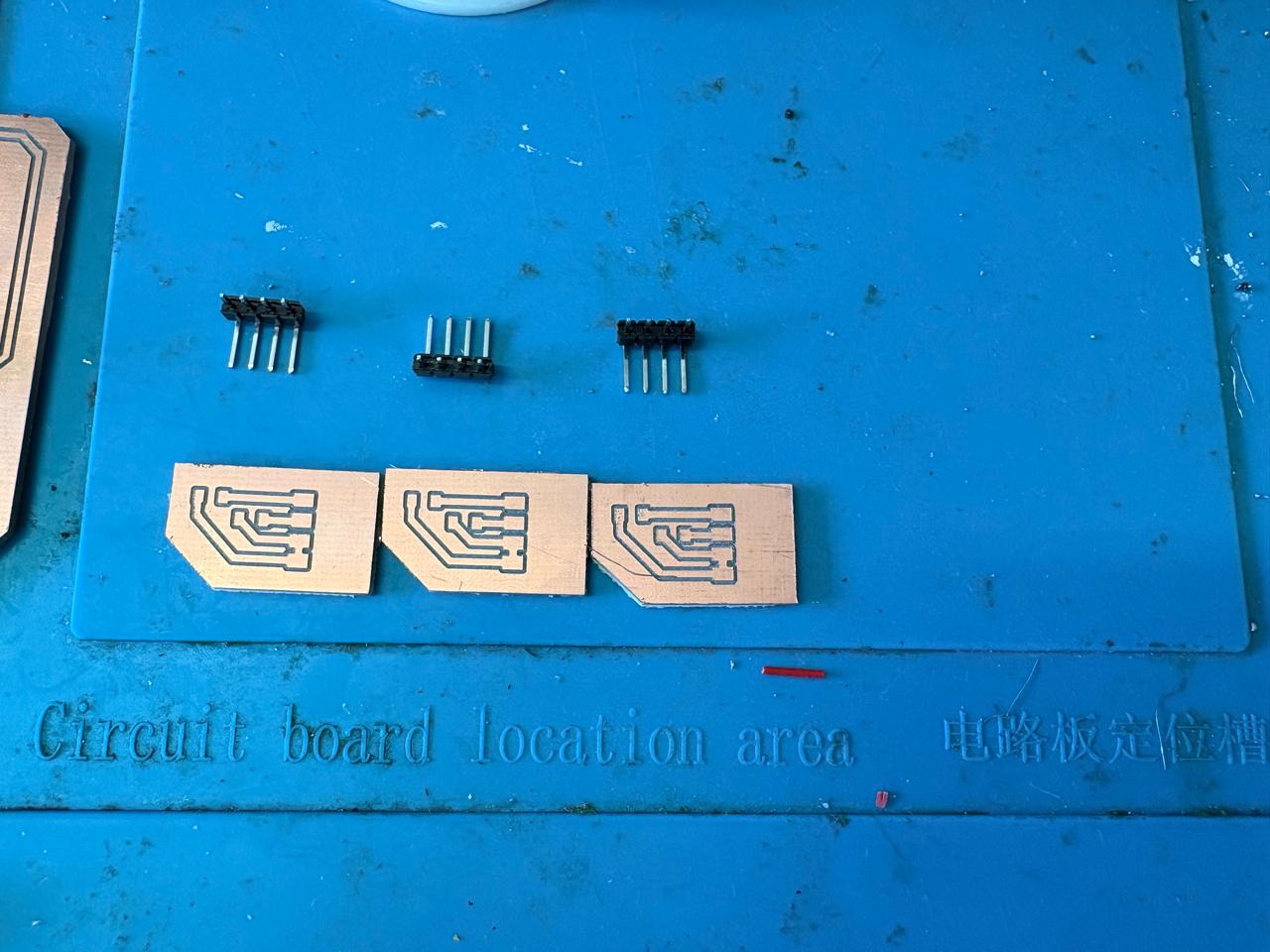
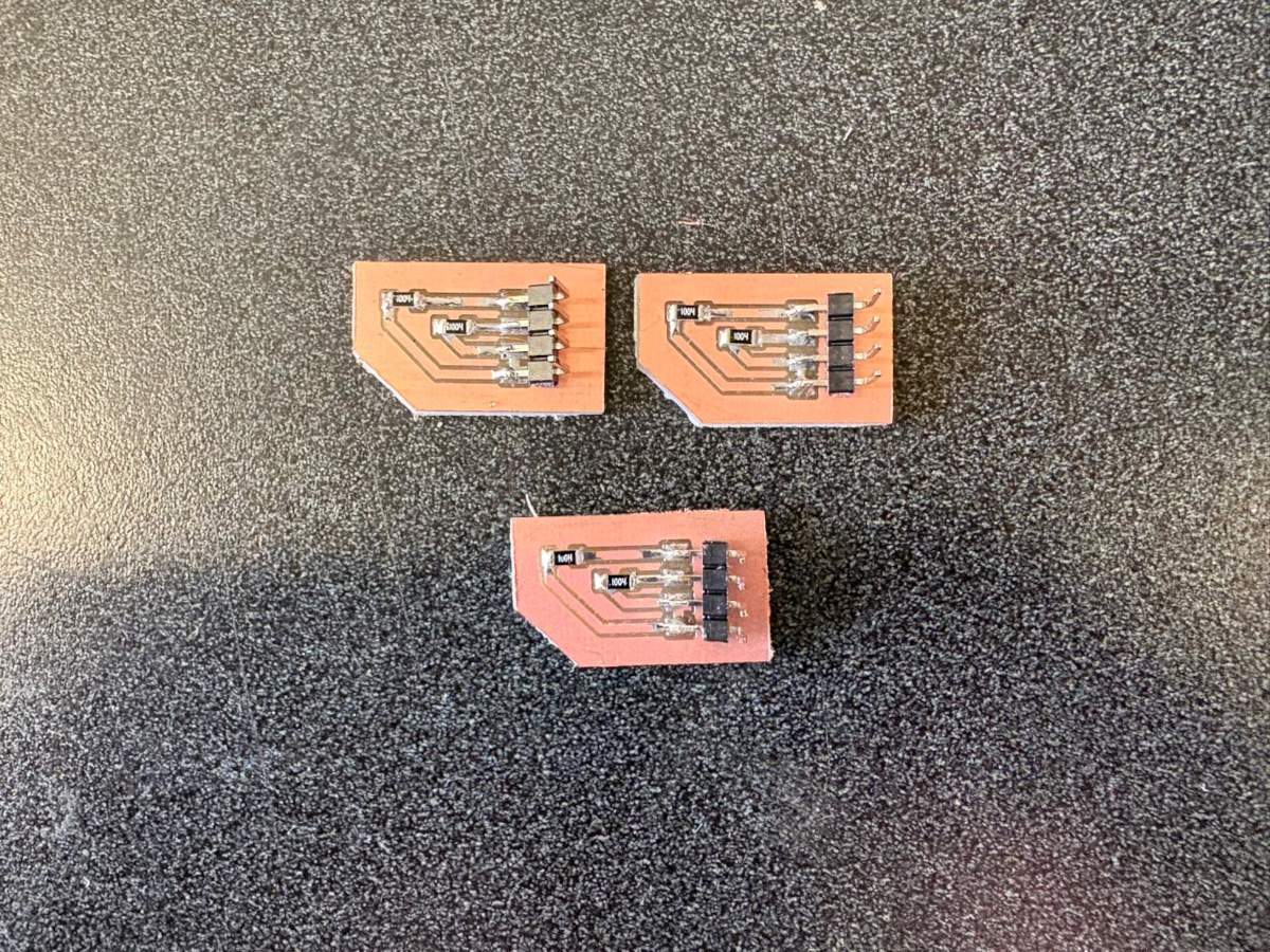
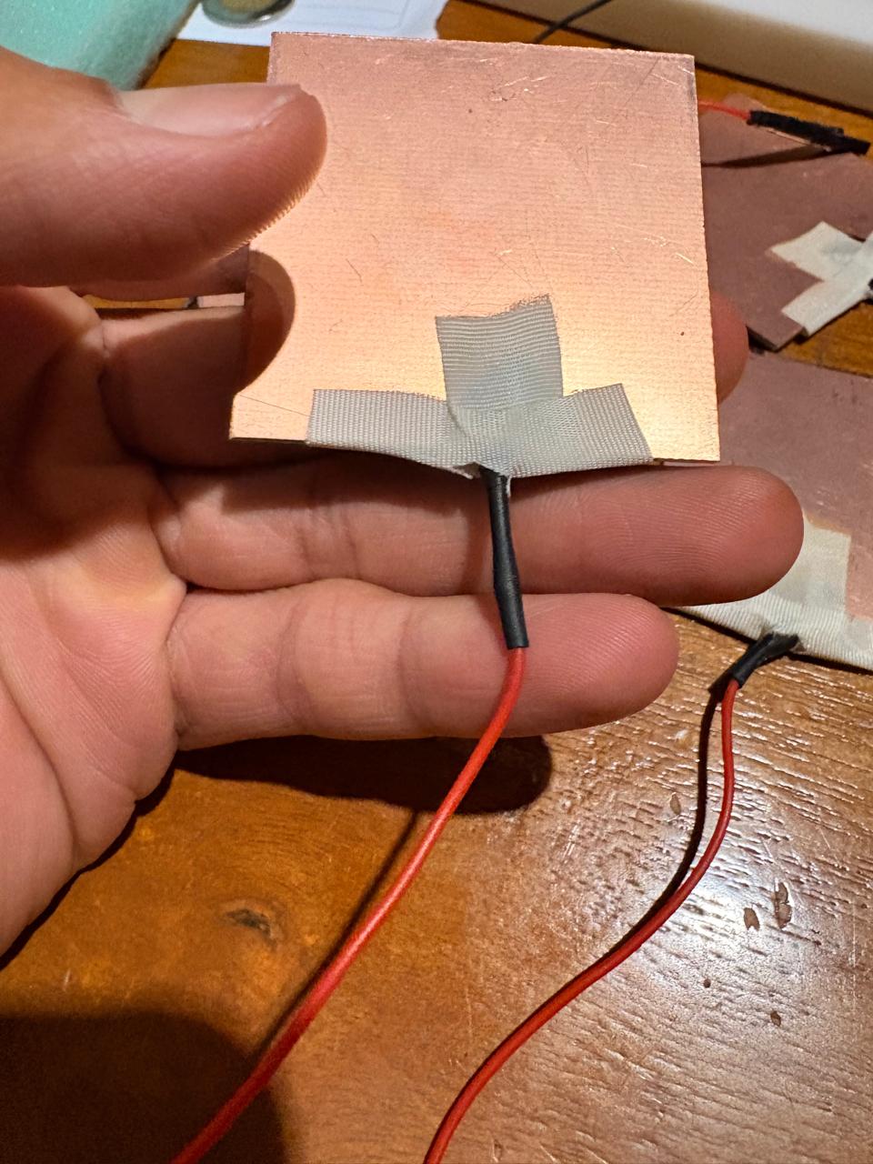
Step Response
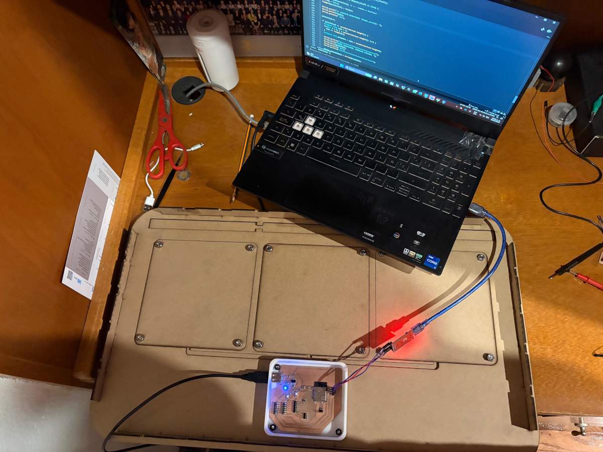
ESP32, Inputs & Outputs Code
B.R.I.S. Code
Interface
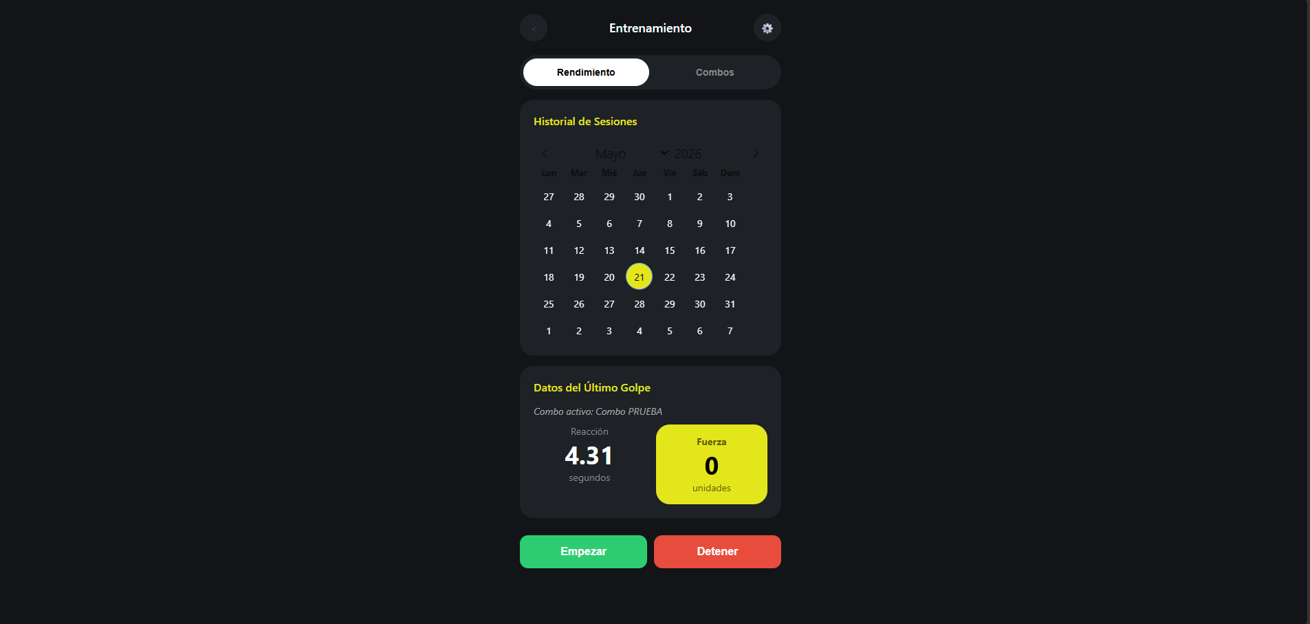
B.R.I.S. INTERFACE
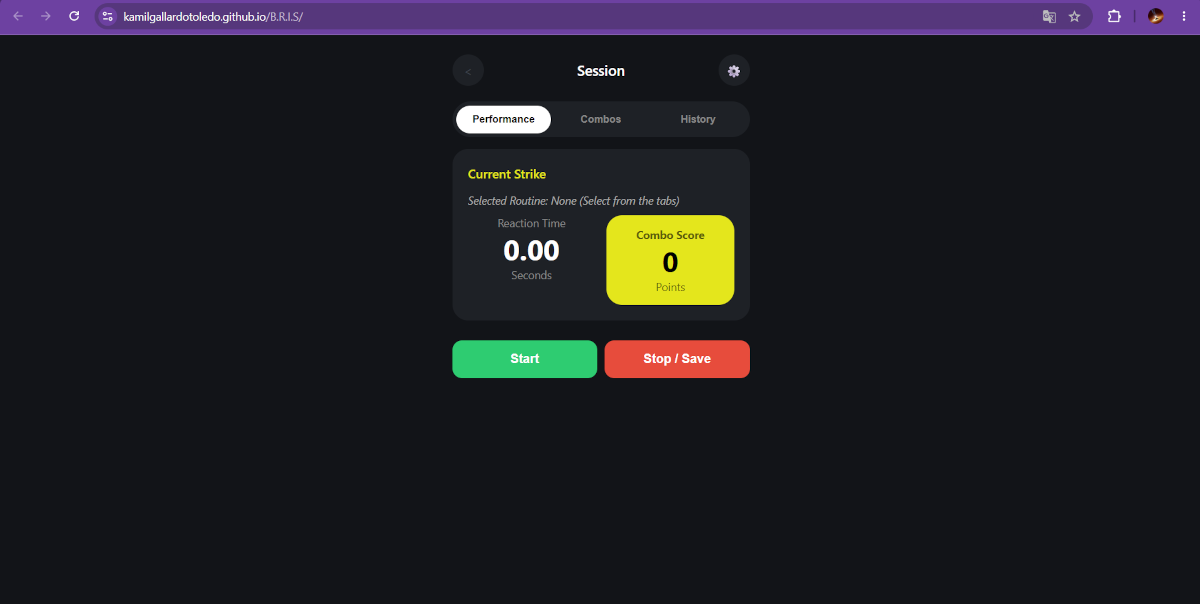
If you want to take a look at the interface click here B.R.I.S.
Integration & Packaging
Part Design & 3D Printing
NEOPIXELS case
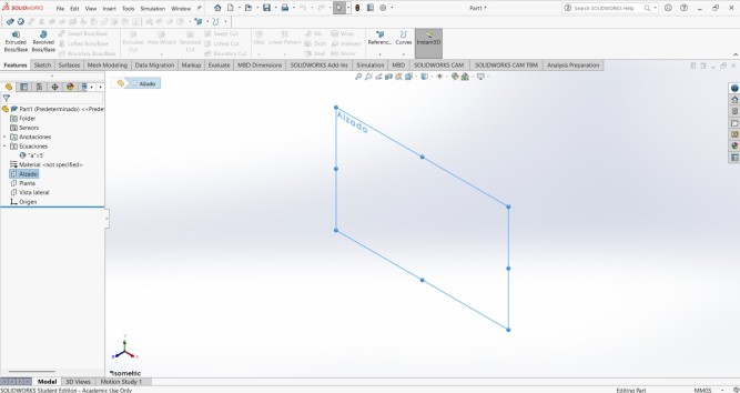
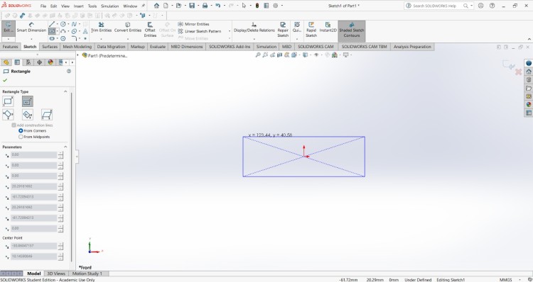
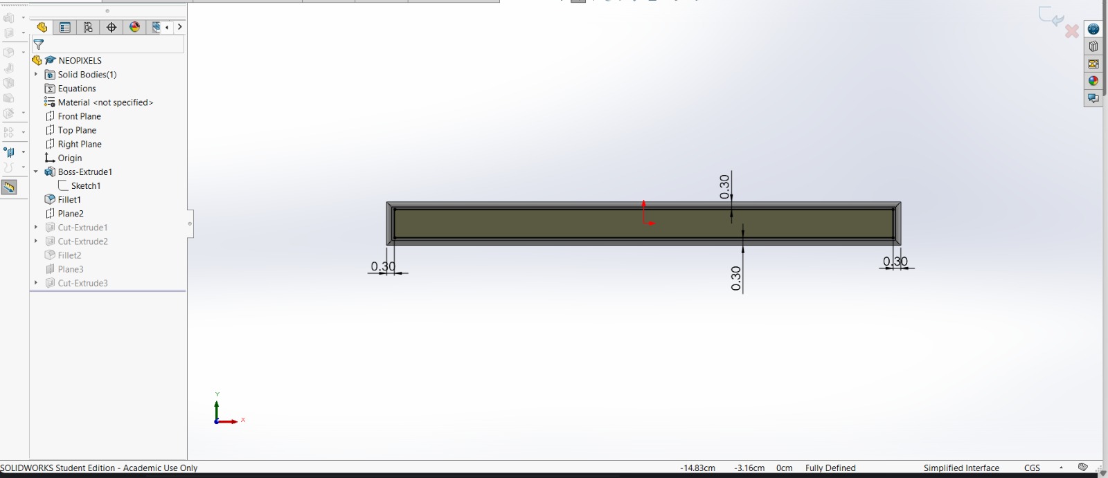
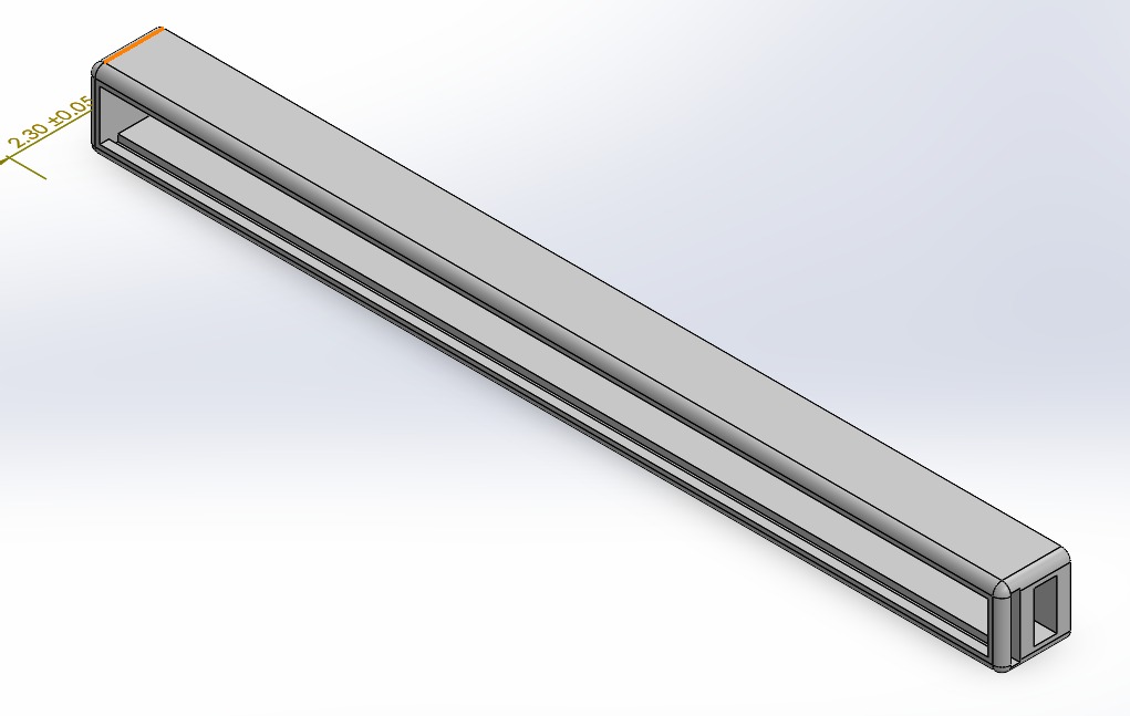
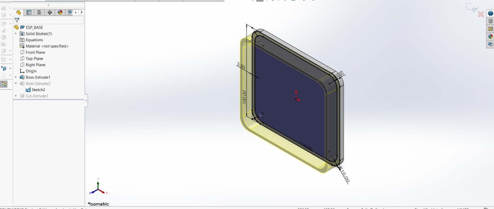
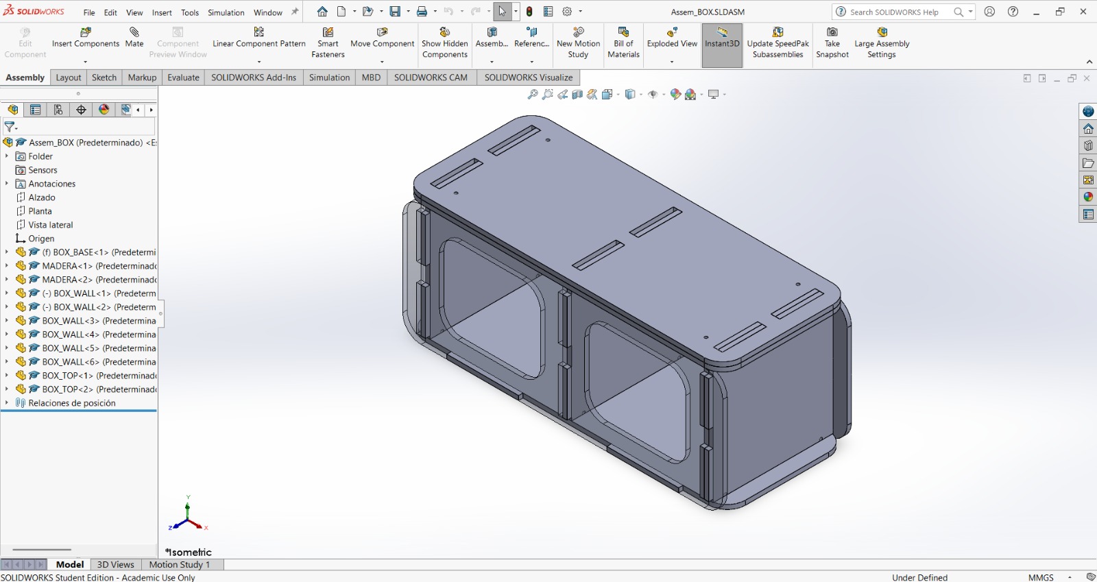
1. First, I changed the document units to CGS and created a center point rectangle of 1.7 X 18 cm in the front plane.
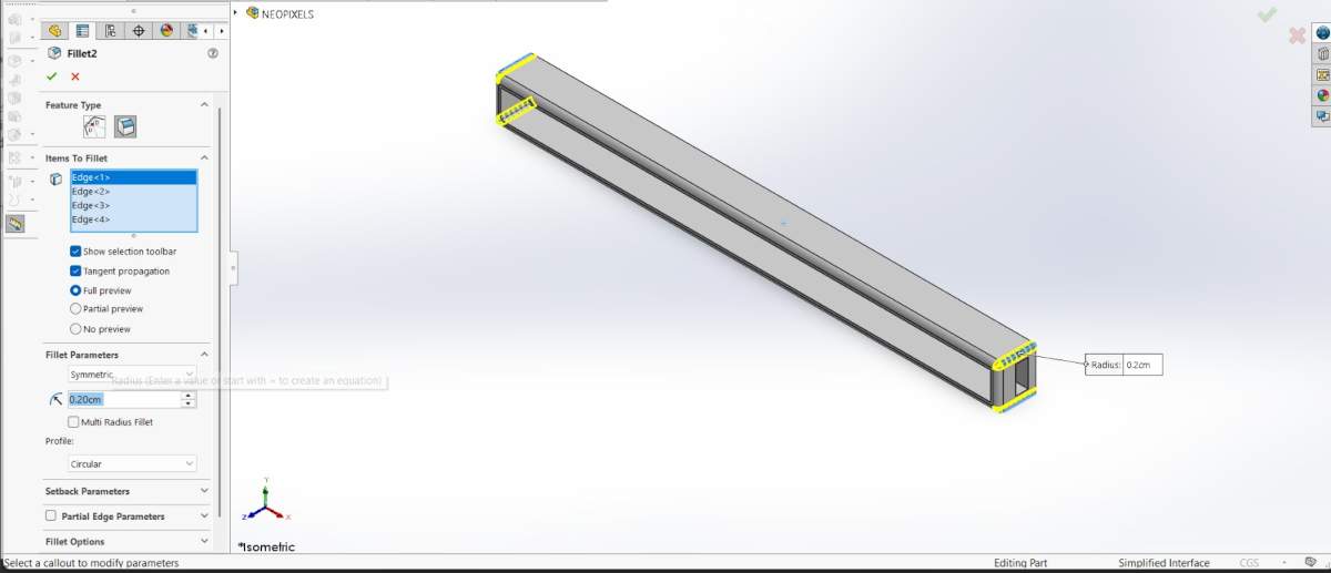
NEOPIXELS case
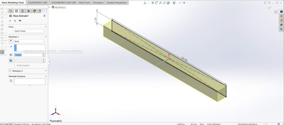
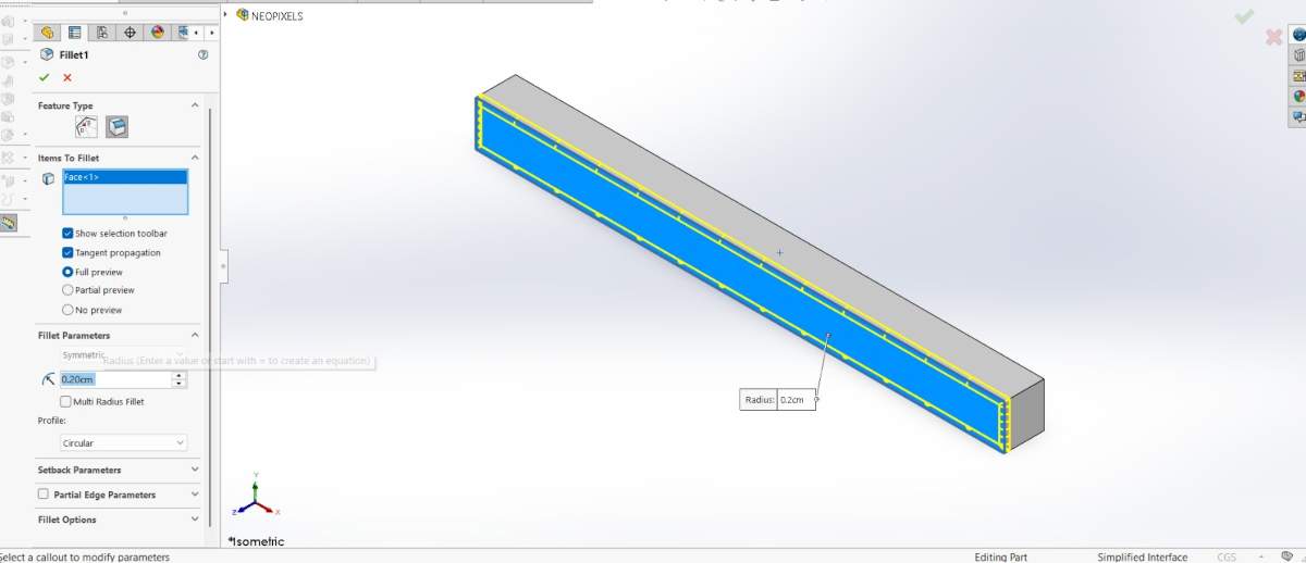
2. Then, I extruded it 1.5 cm and made roundings of 0.20 cm.
NEOPIXELS case
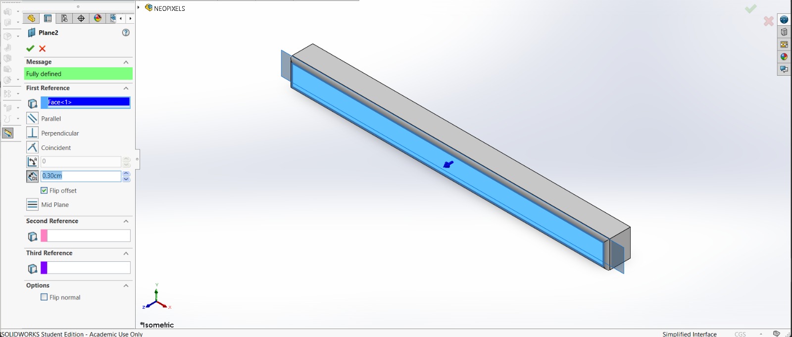
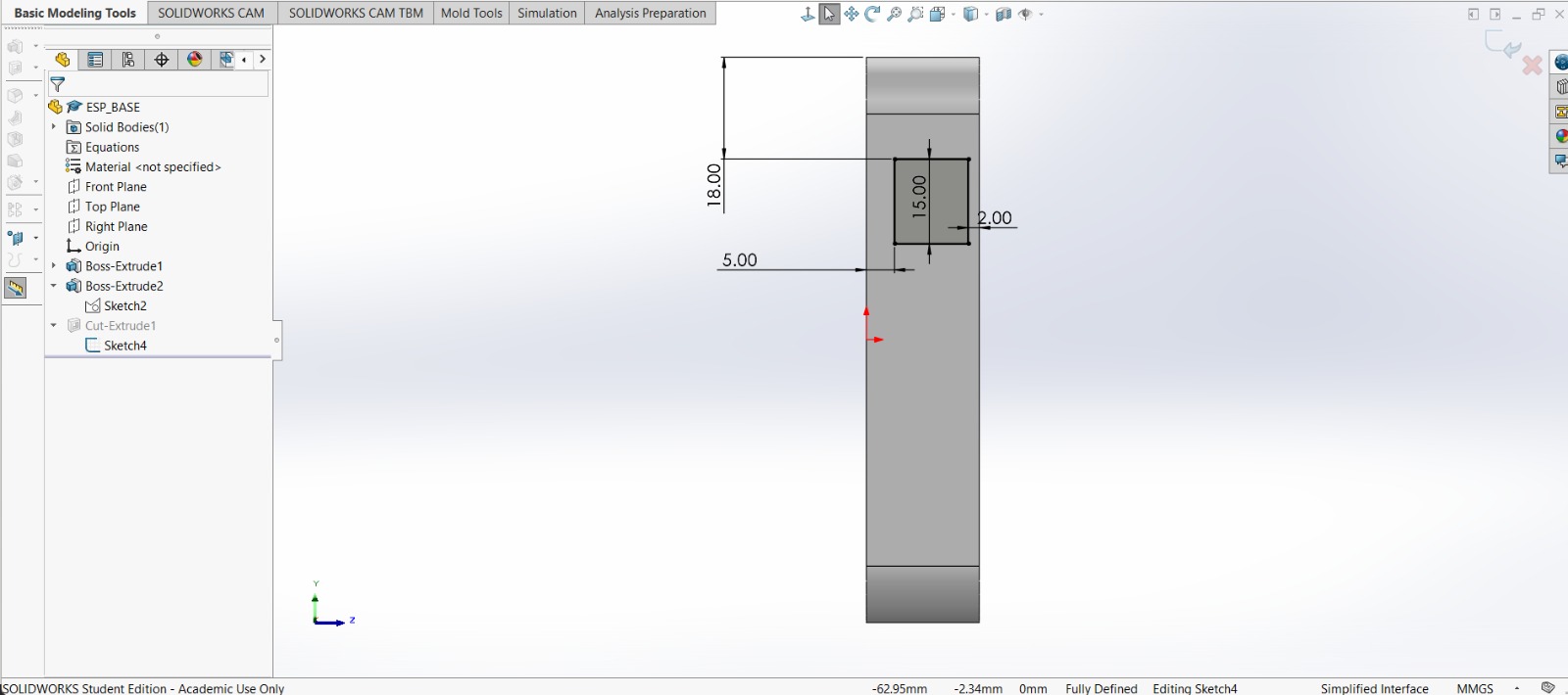
3. After that, I made a plane 0.30 cm from the front face of the piece.
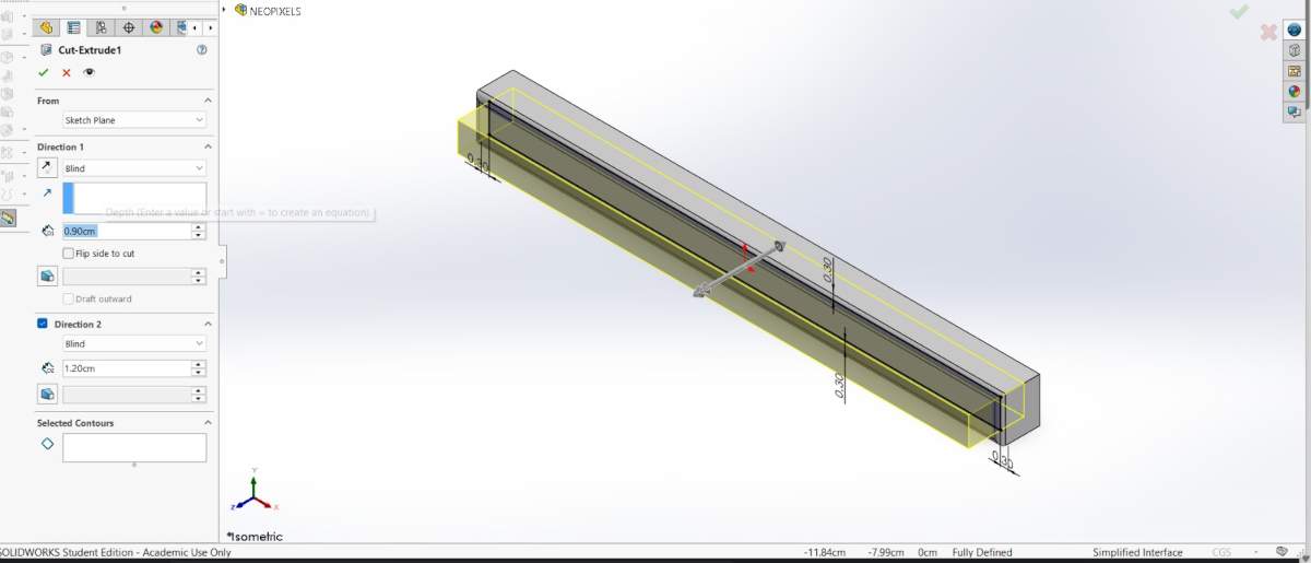
4. And in that plane made a rectangle with a distance of 0.30 cm from each edge. Then, I extruded a cut of 0.90 cm inside.
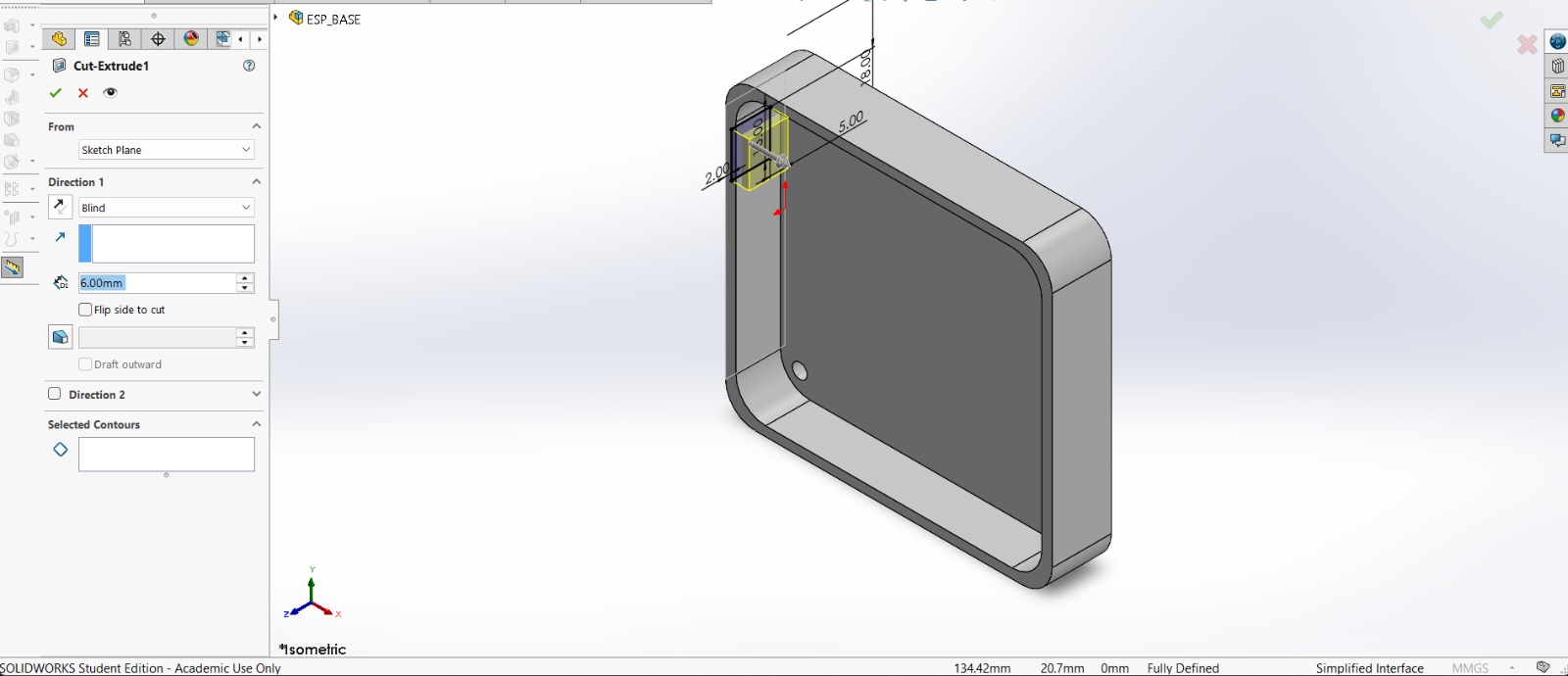
NEOPIXELS case
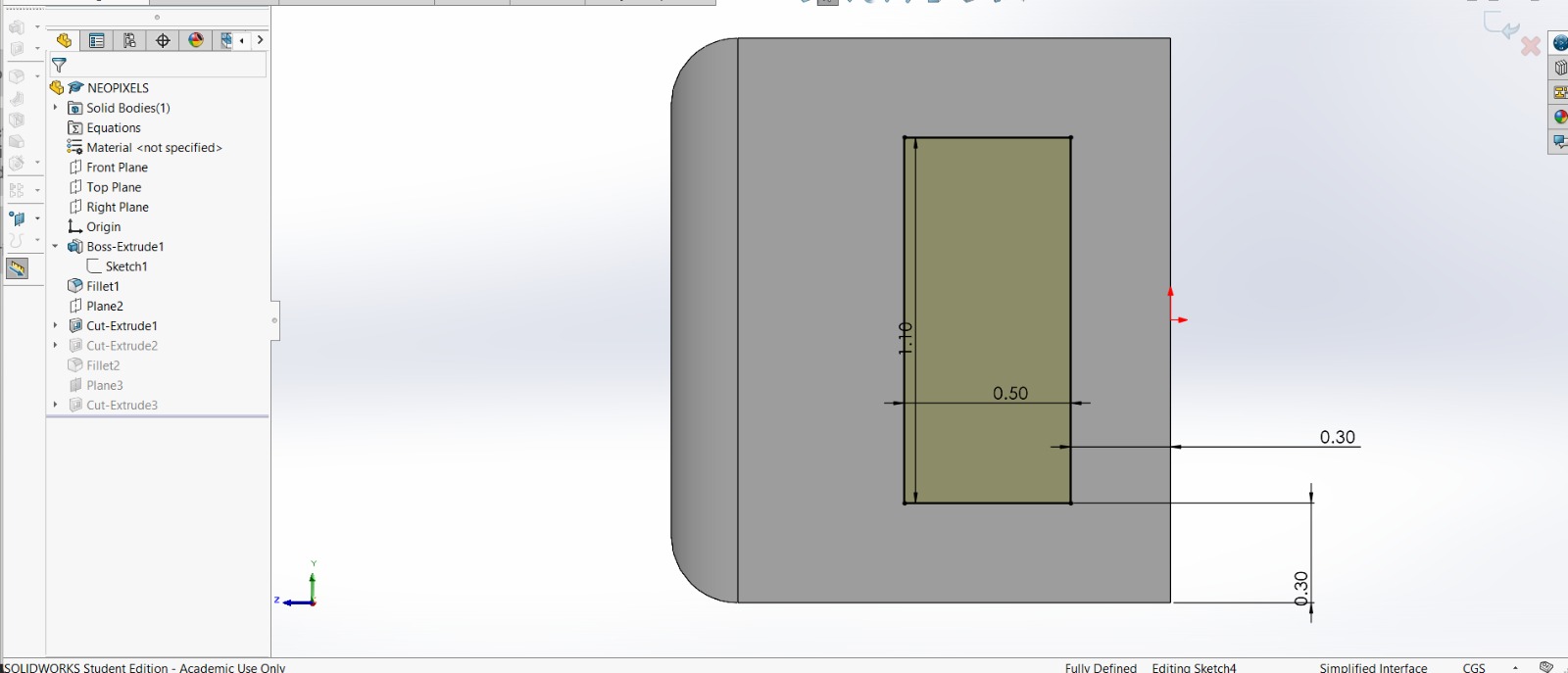
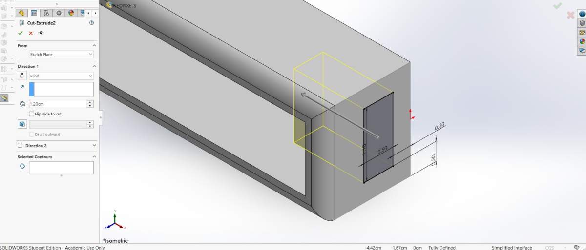
5. Subsequently, in the lateral face of the piece I made a rectangle of 1.10 X 0.50 cm at a distance of 0.30 cm from each edge. Next, I extruded a cut inside. I also added roundings in the corners so it could look better.
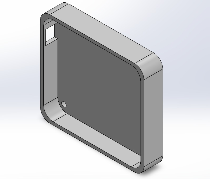
NEOPIXELS case
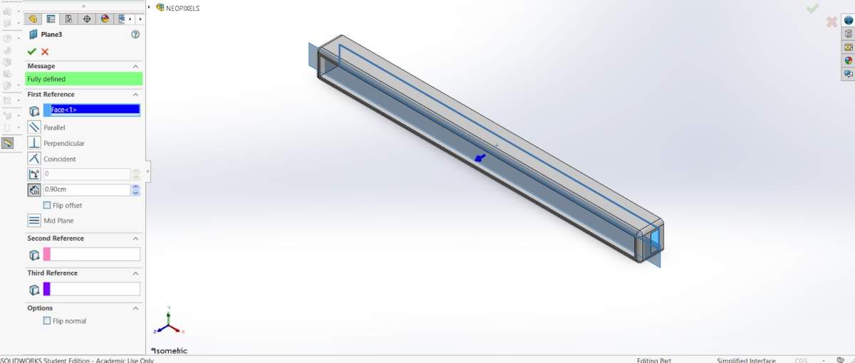
6. After that, I made a plane 0.90 cm from the back face of the piece.

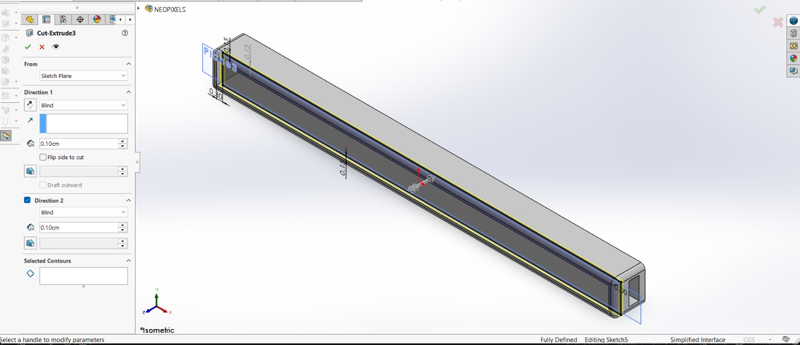
7. Then I added a rectangle to create a tab where I could later insert a transparent sheet. Then, I extruded a cut of 0.10 cm inside and outside.
Results
~ Export. We have to export our piece as an STL so we can print it. For that, we must go to File, then look for Save as and save it as STL.
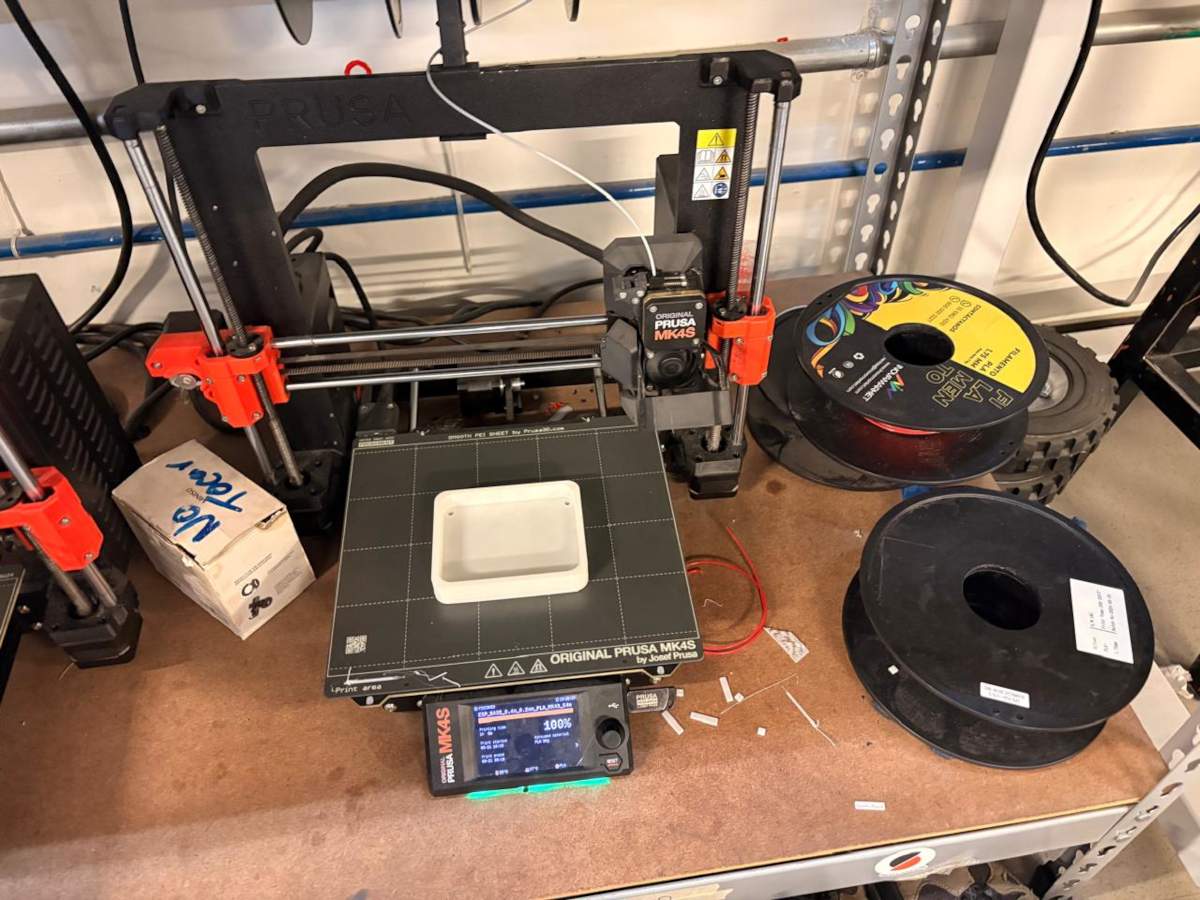
Printing
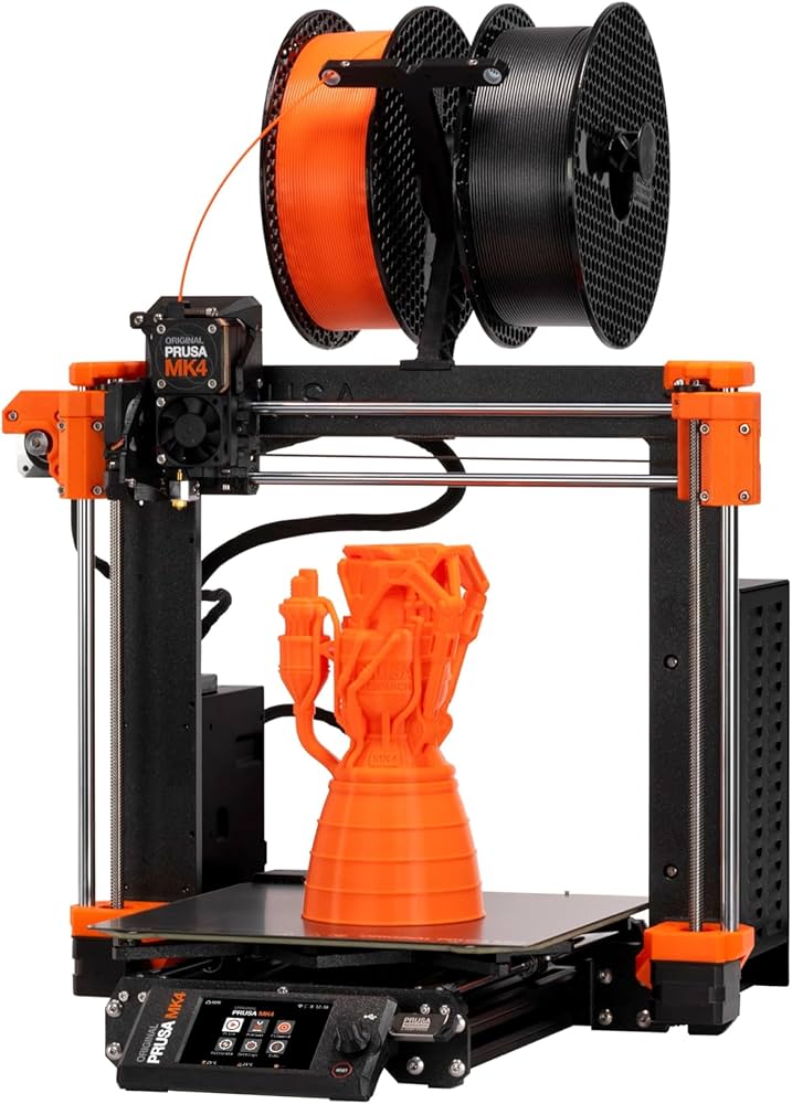
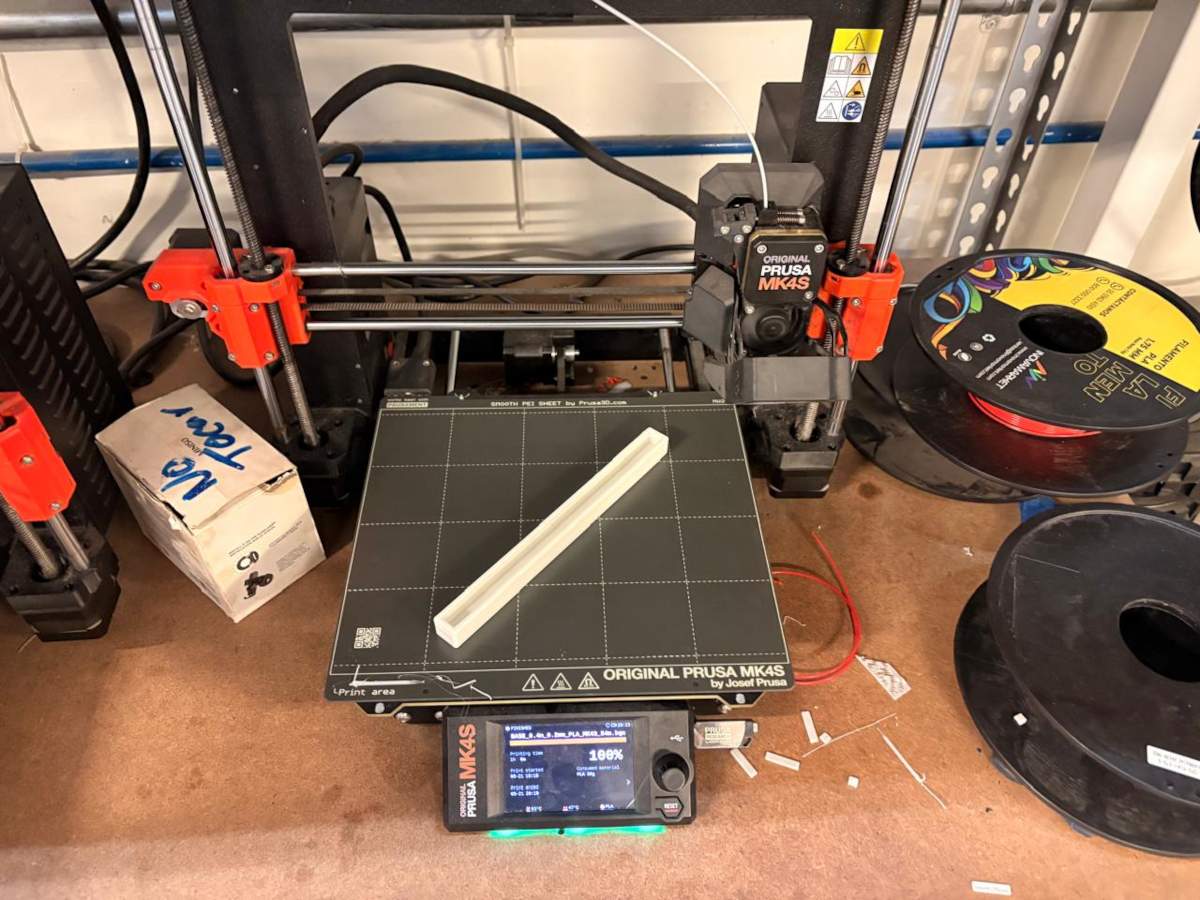
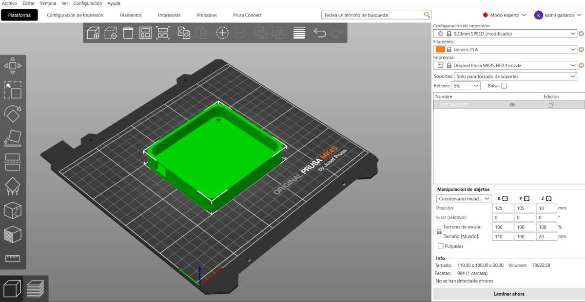
~ Slicer: To print, I used Prusa Slicer. I will also use a Prusa MK4S for the 3D printing process.
NEOPIXELS case
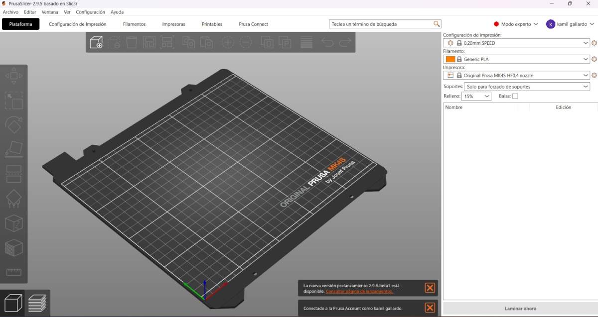
1. First, open the slicer and import the STL piece.
NEOPIXELS case
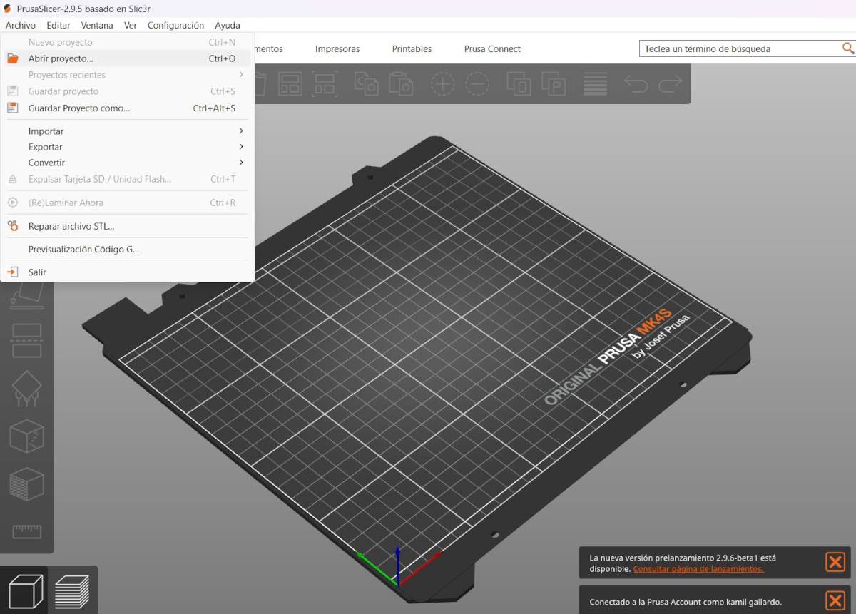
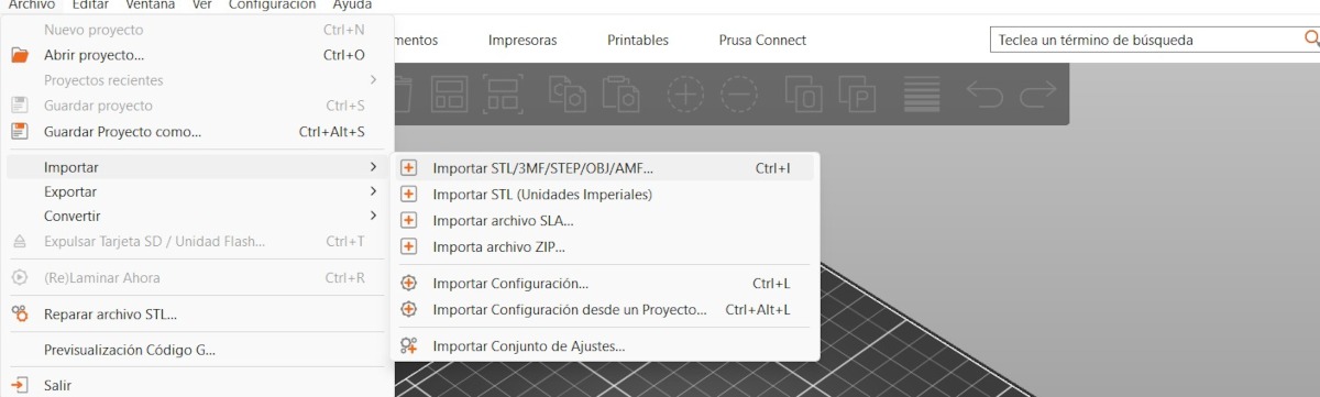
2. For importing, we have to press File, then import and select import STL.
NEOPIXELS case
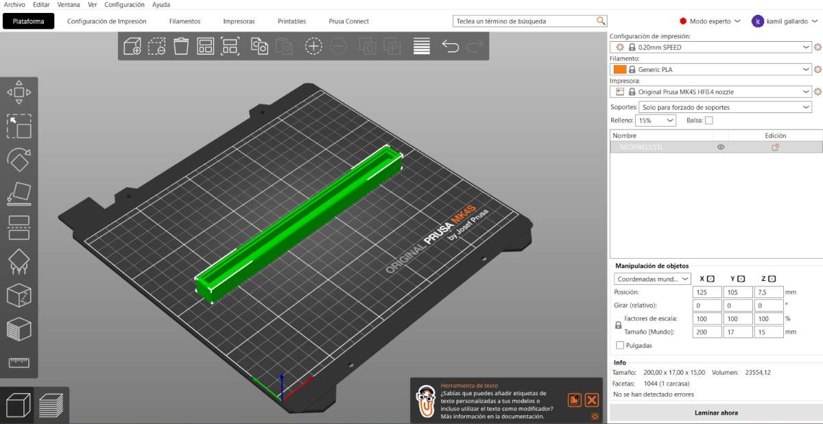
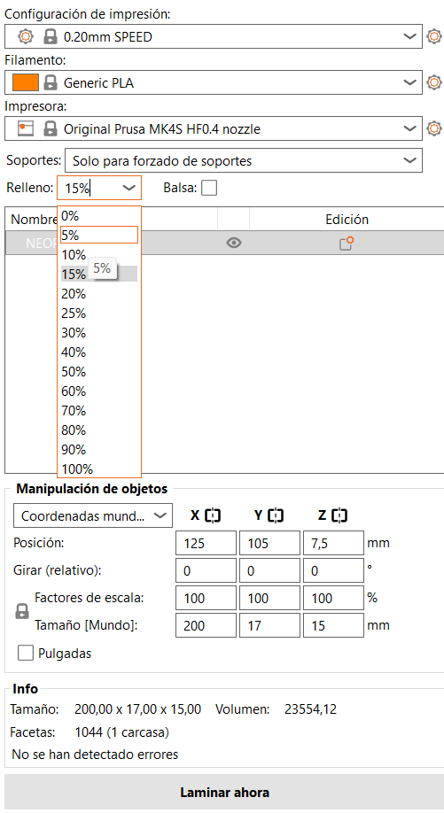
3. After that, we have to set the printing parameters. Being honest, I just placed my piece on the center, changed the material to PLA and also changed the infill to 5%.
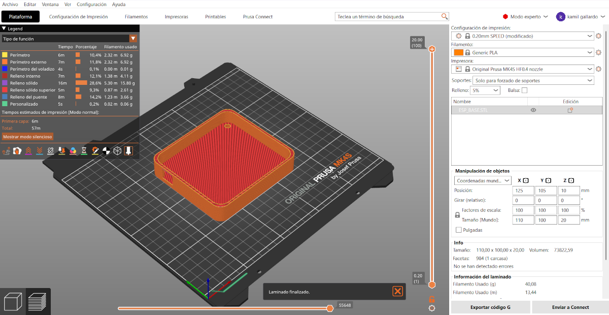
4. Then, we just have to press the button at the bottom labeled as SLICE.
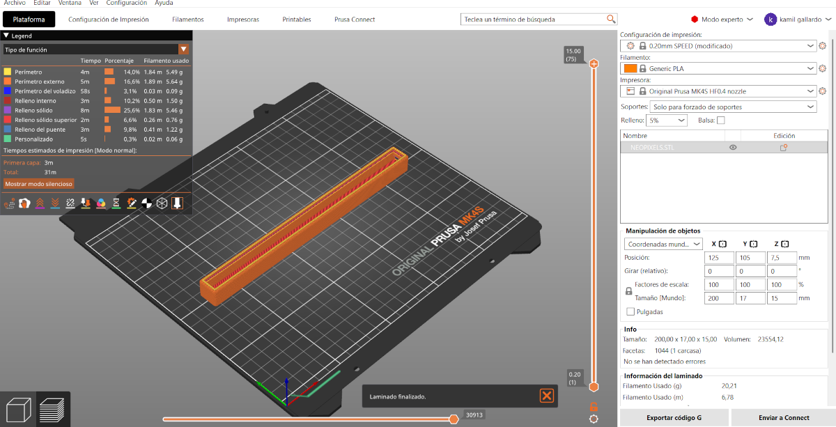
5. Having sliced our piece, we can see the way it will be printed and, by pressing the button below, we can save it in the Prusa USB.
Results
System Integration
After week 15, I made changes to the structure to improve the assembly’s usability and durability, and also, to have a packaging for my project. Among the most significant changes are a reduction in the horizontal size, reduction in the space between the pads, engraving on the front panel, and fine-tuning of the screw sizes and spacing between components.
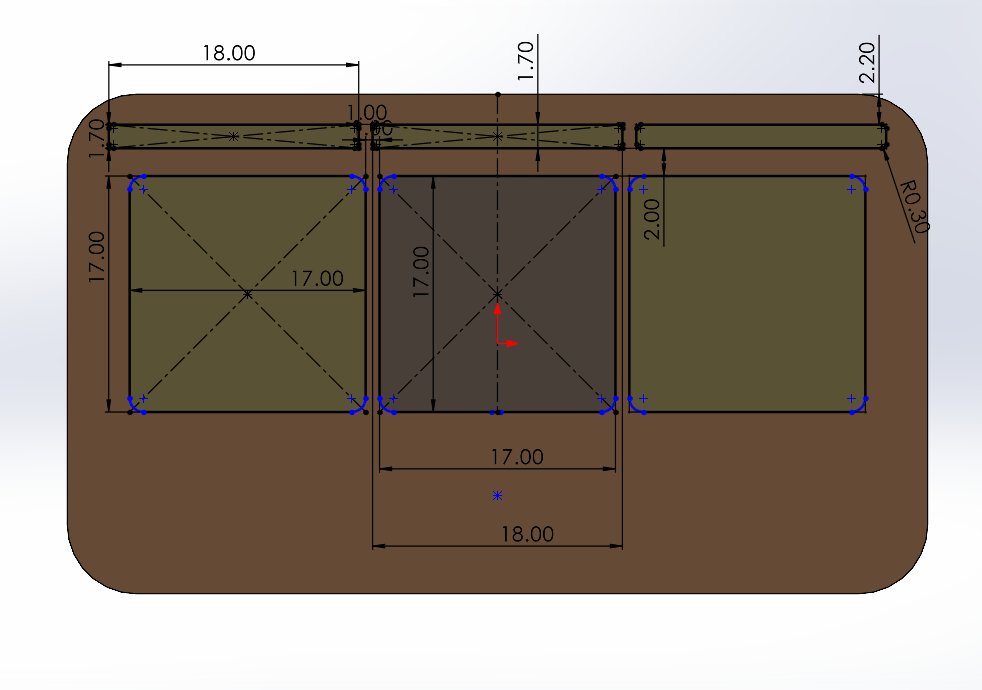
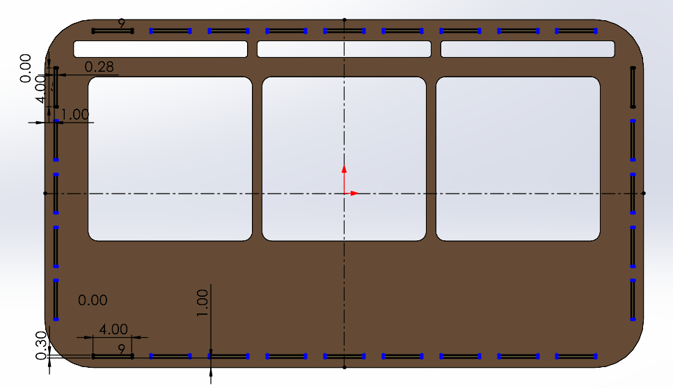
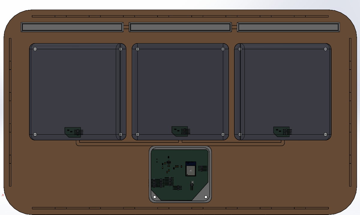
Position footprint
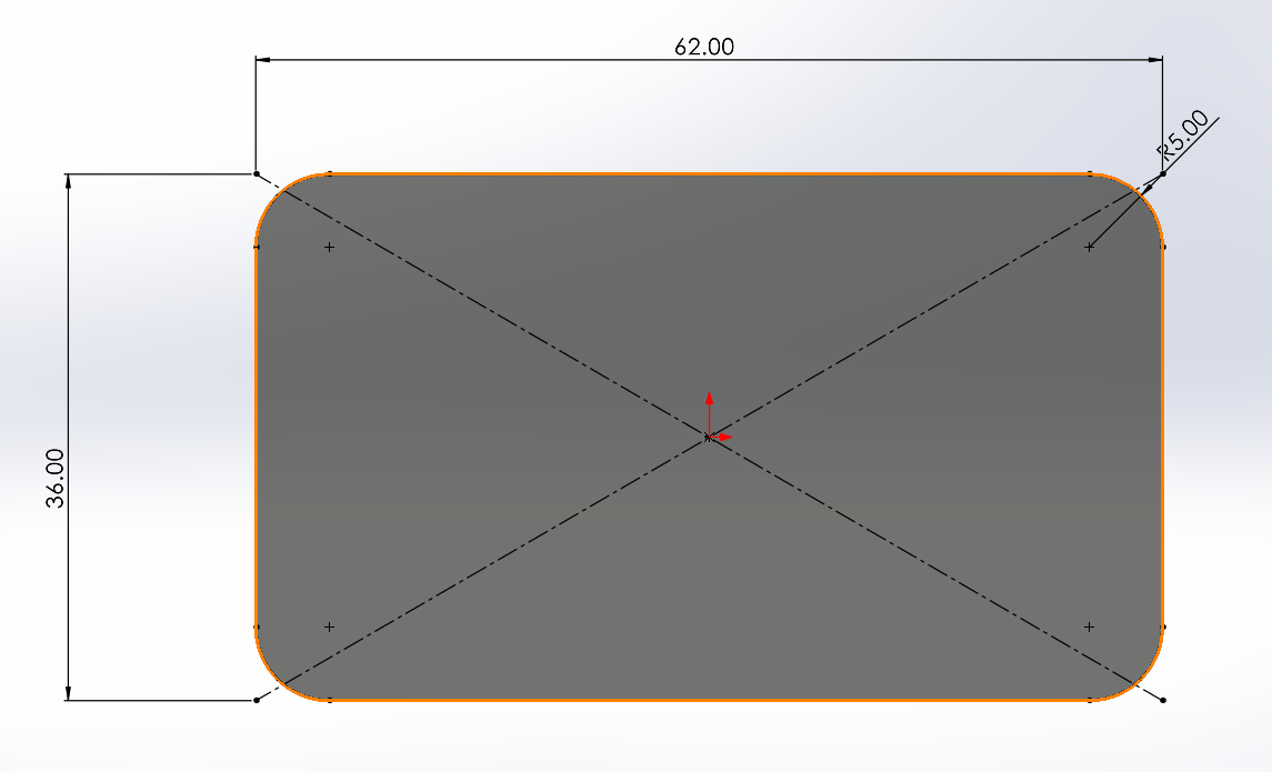
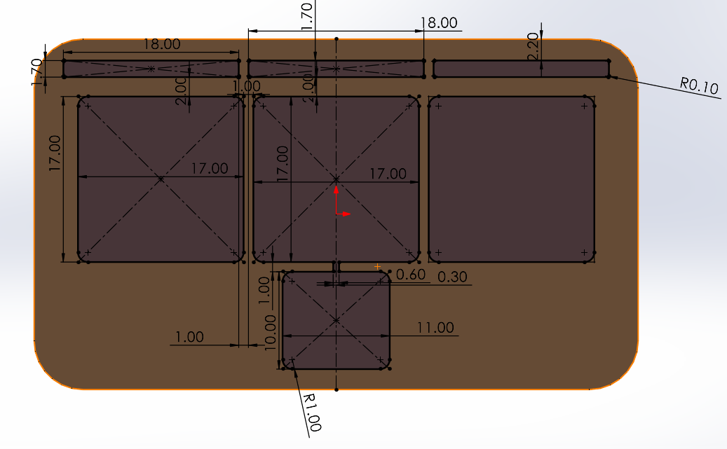
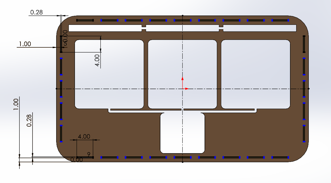
PIECE. First, I changed the document units to CGS and created a center point rectangle of 62 X 36 cm in the front plane. Then, I made fillets of 5 cm of diameter and extruded it 3 mm. Next, I traced the outlines of the parts I’ll be placing in the assembly, which are: 3 Neopixel casings, 3 pads, and the ESP32 casing. My pads will measure 17 x 17 cm, spaced 1 cm apart, with a 2 cm distance from their respective Neopixels and a 1 cm vertical distance from the center pad to the ESP32 housing. Then I extruded the cut. After that, I made small conduits of 6 mm to keep the wires from my components tidy. They all go to the ESP32. Finally, I made small joints around mi piece.
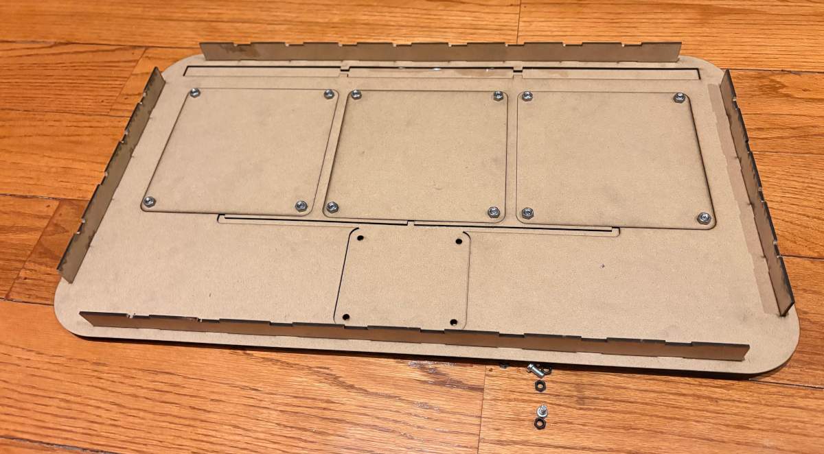
BASE
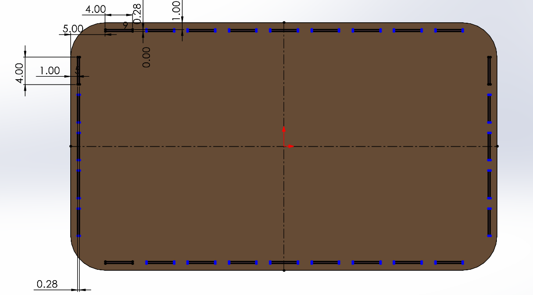
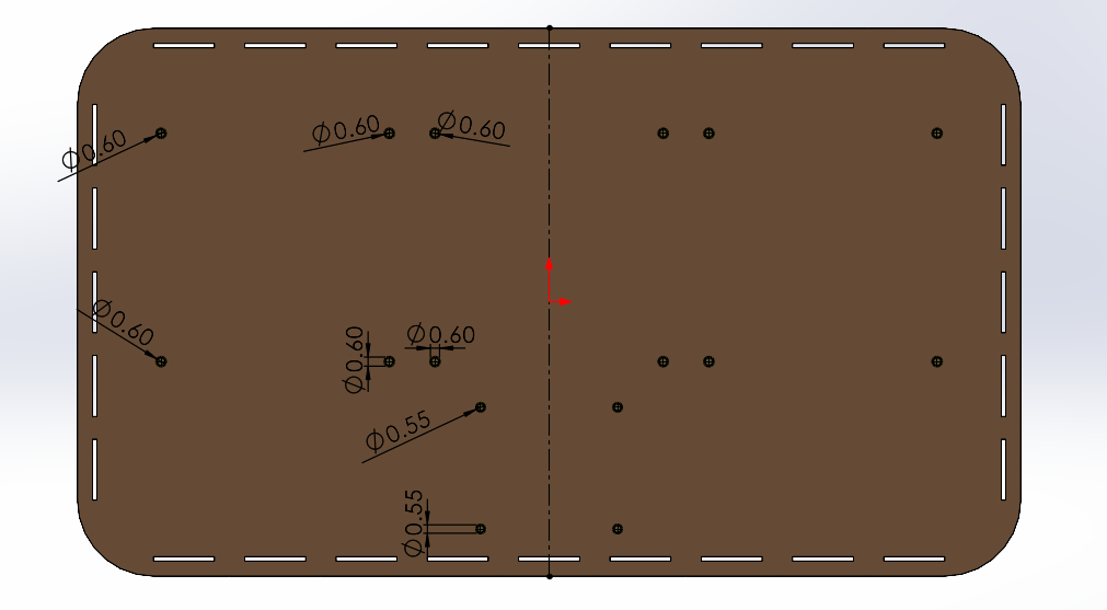
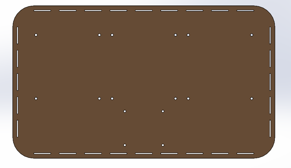
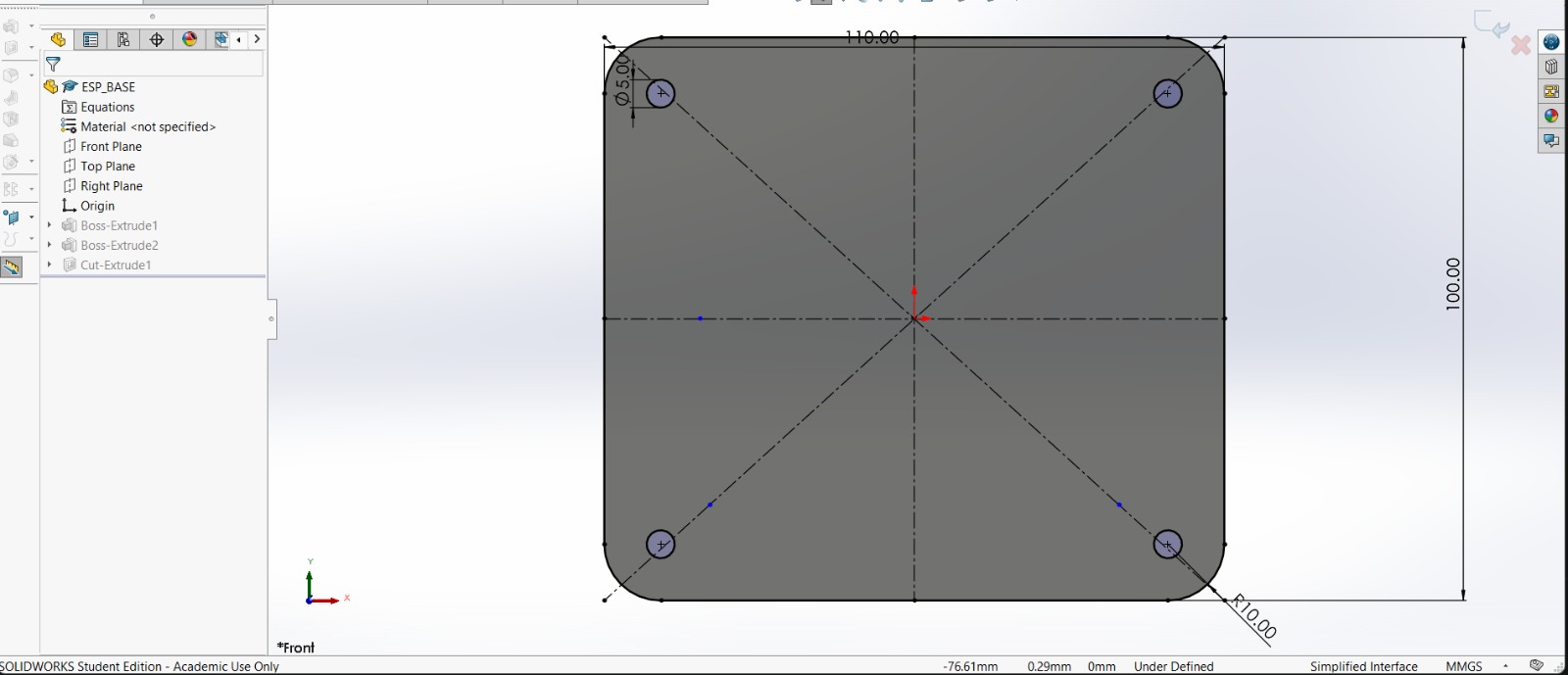
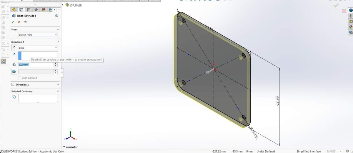
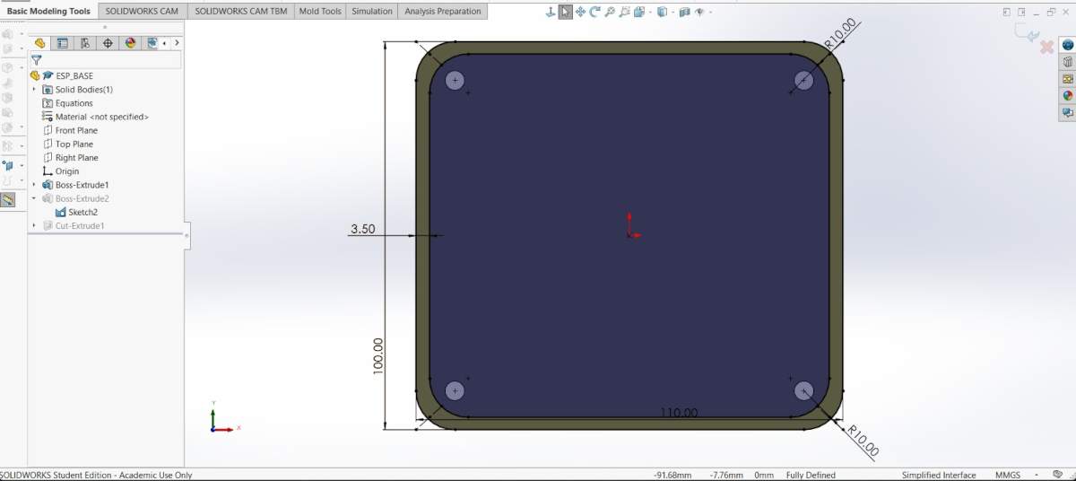
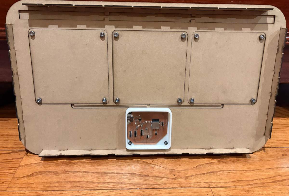
PIECE. First, I changed the document units to CGS and created a center point rectangle of 62 X 36 cm in the front plane. Then, I made fillets of 5 cm of diameter and extruded it 3 mm. After, I made small holes located in the corners of the Pads and the ESP32 case, to attach them to the board. Finally, I made small joints around my piece.
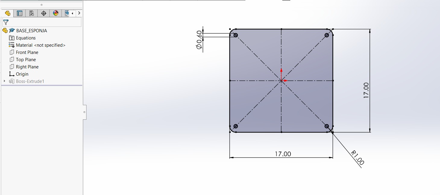
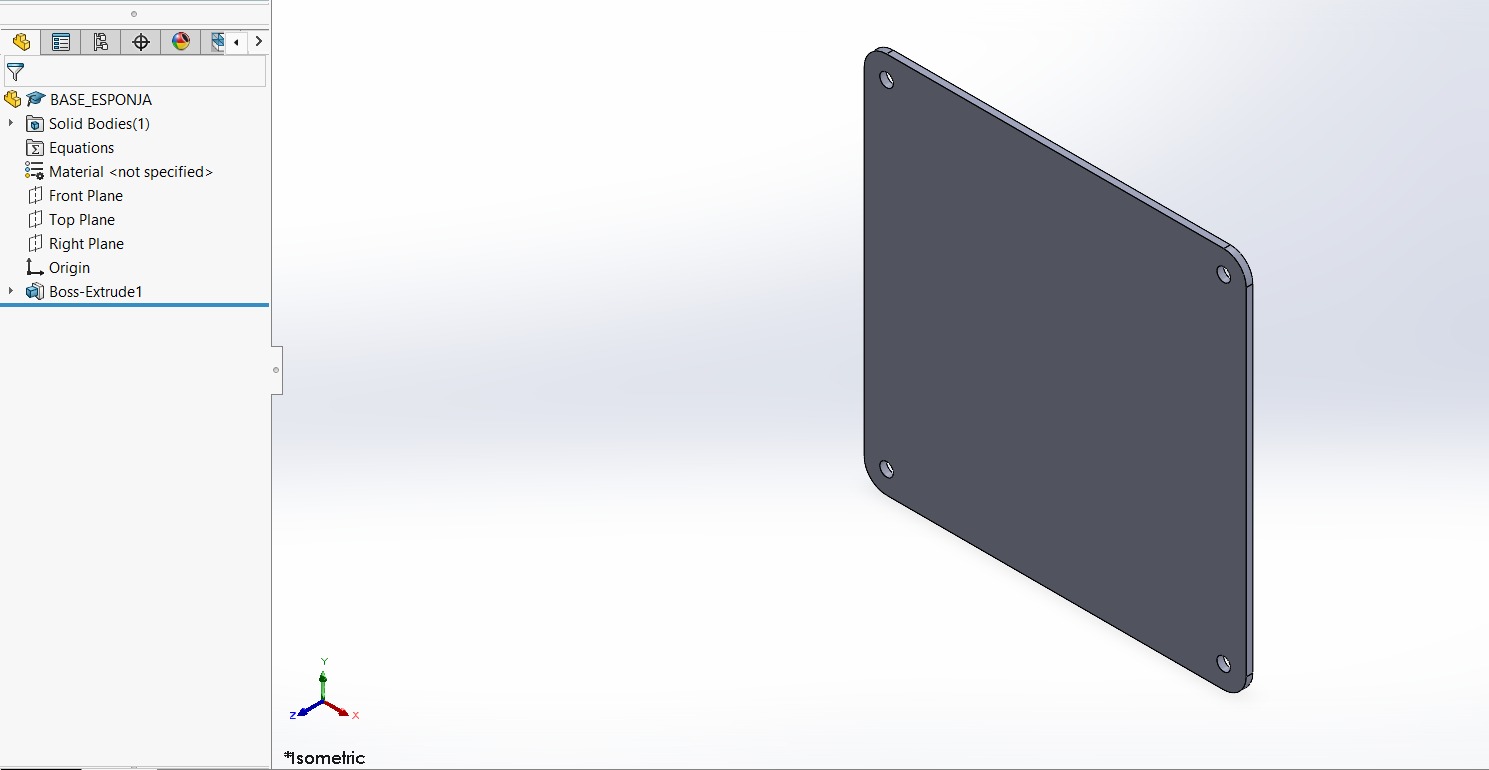
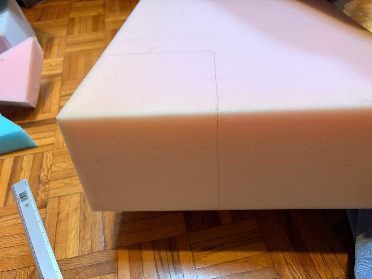
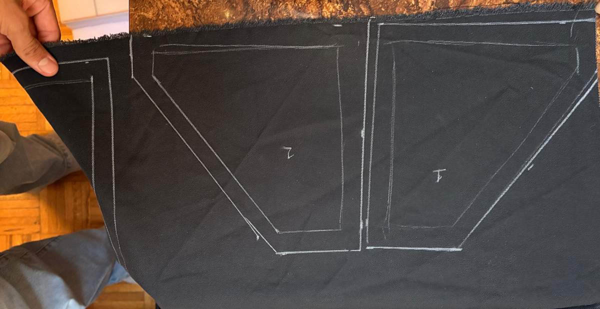
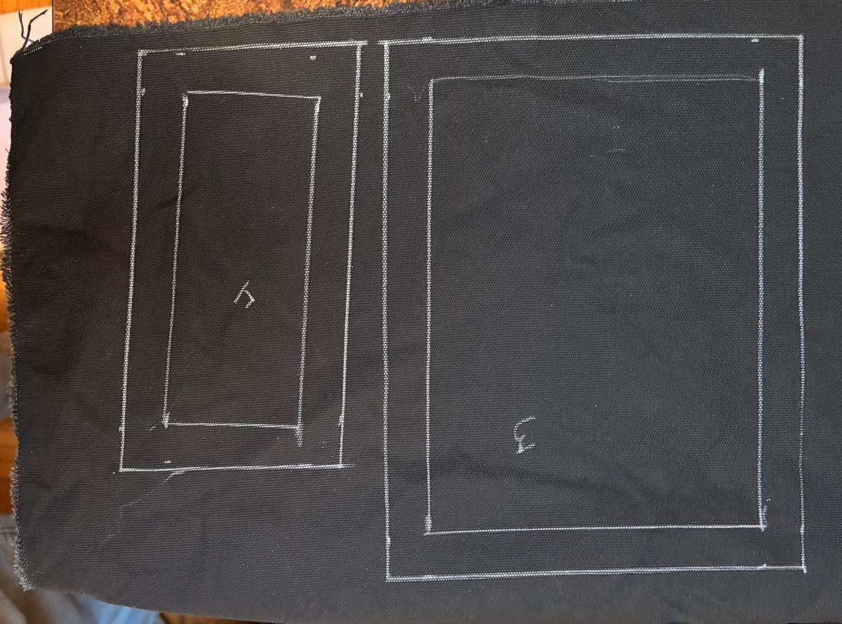
PAD BASE. Also create the bases for the pads; this is to provide them with better support. They measure 17 x 17 cm, with a 1-cm fillet, and have the same 6-mm holes 1 cm from the side and top edges.
WALLS
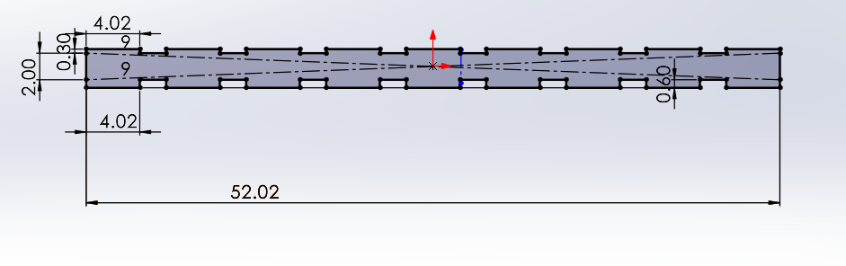
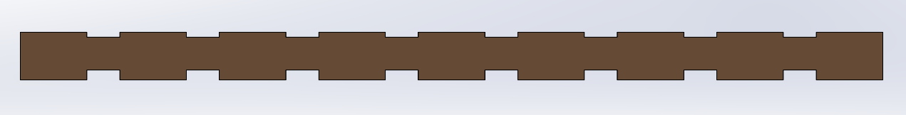
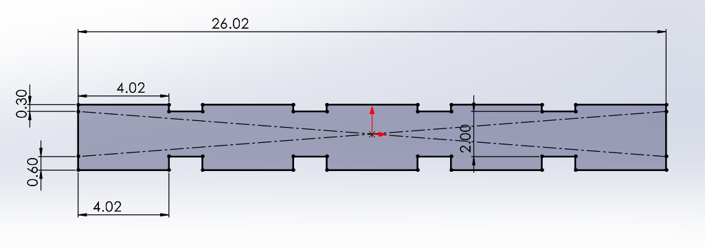
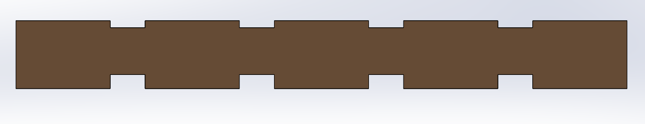
PIECE. The lateral wall design consists of 5 teeth at the top and bottom. The top teeth measure 4.02 × 0.3 cm and the bottom teeth 4.02 × 0.6 cm, taking into account the kerf and the fact that the bottom must fit into two layers 0.3 cm thick. I then extruded it by 0.3 cm. The design of the top and bottom walls consists of 9 teeth on each side. The top teeth measure 4.2 x 0.3 cm and the bottom teeth measure 4.2 x 0.6 cm, taking into account the kerf and the fact that the bottom section must fit into two layers, each 0.3 cm thick. I then extruded it by 0.3 cm.
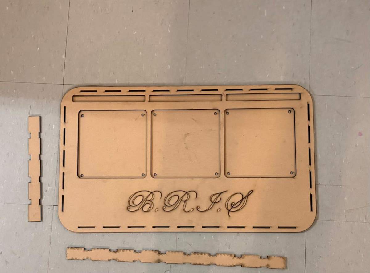
FRONT FACE
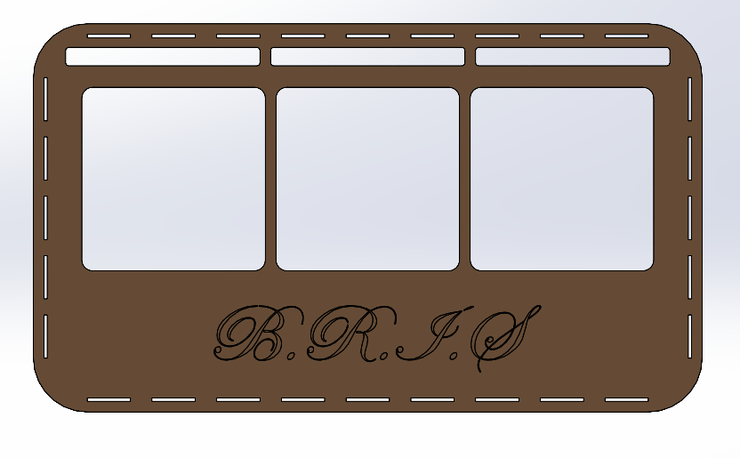
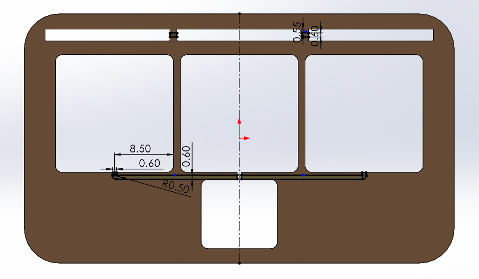
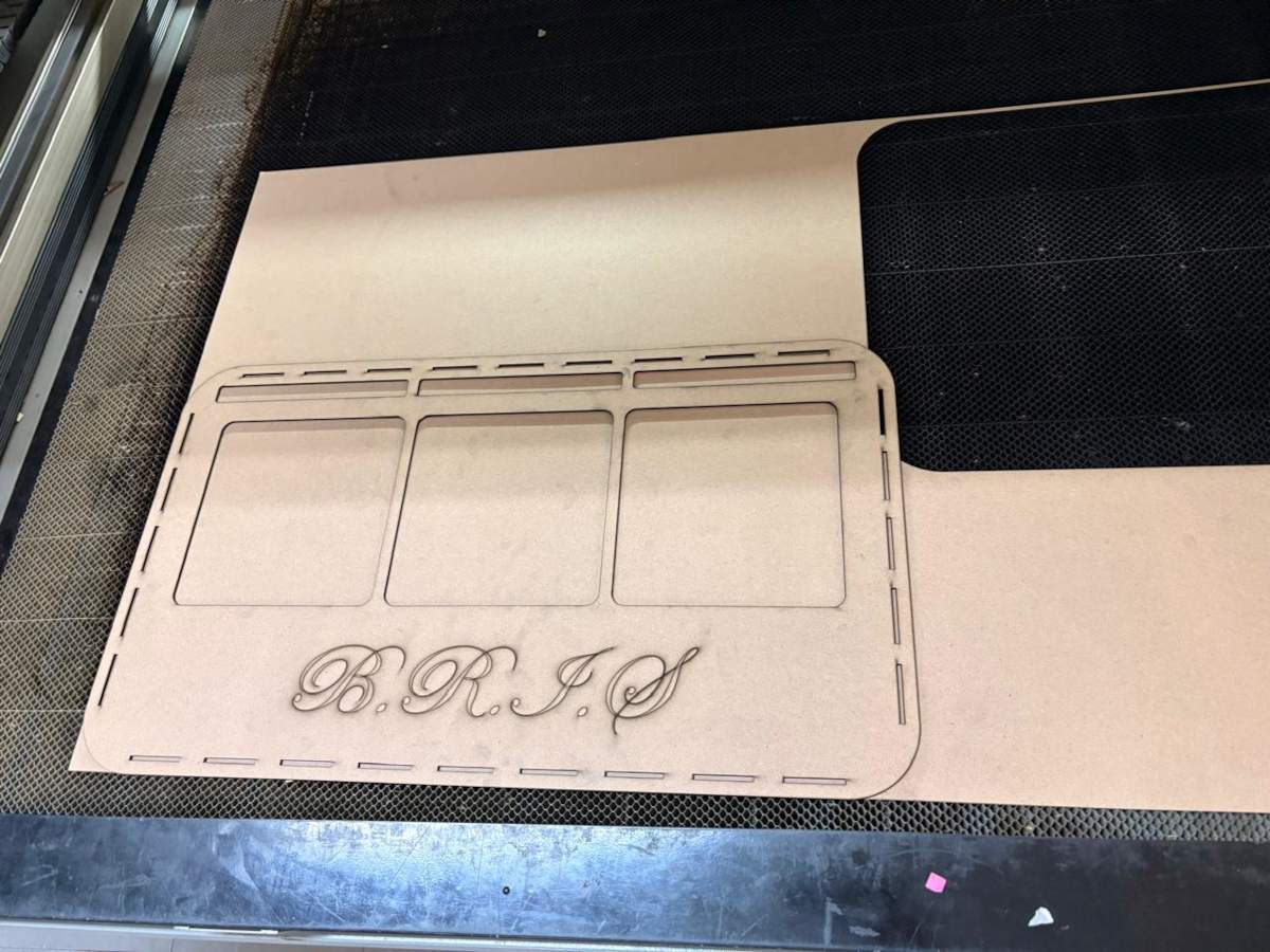
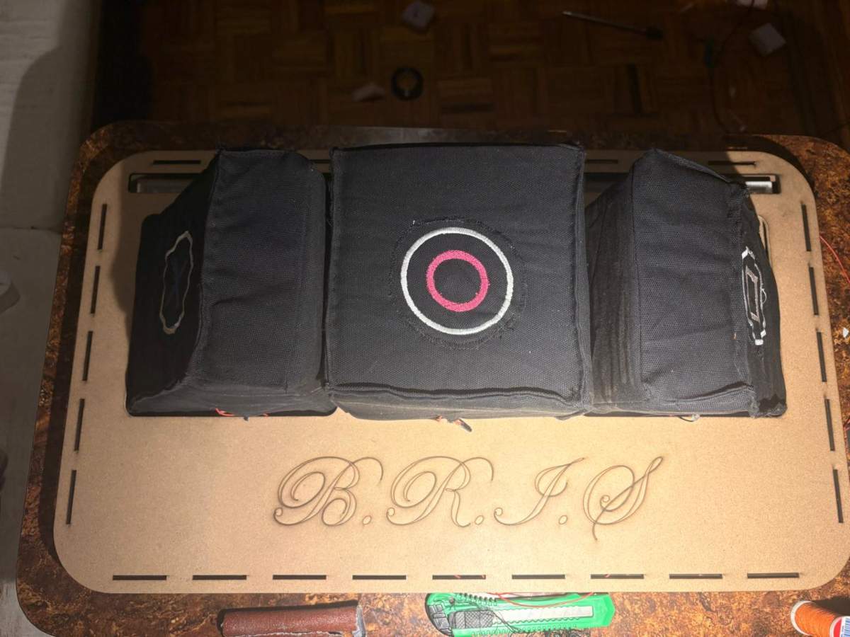
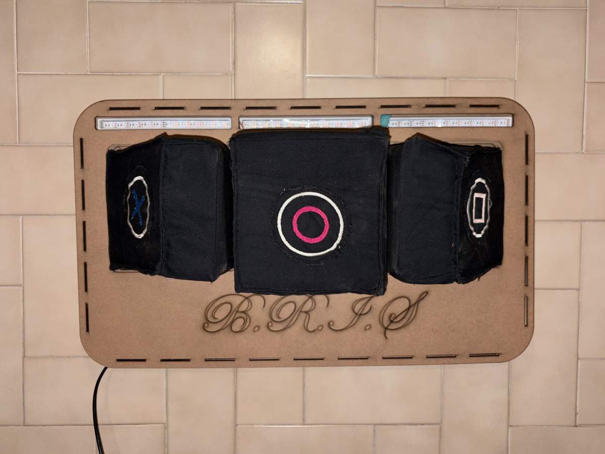
PIECE. First, I changed the document units to CGS and created a center point rectangle of 62 X 36 cm in the front plane. Then, I made fillets of 5 cm of diameter and extruded it 3 mm. Next, I traced the outlines of the parts placed , which are: 3 Neopixel casings and 3 pads. My pads will measure 17 x 17 cm, spaced 1 cm apart, with a 2 cm distance from their respective Neopixels. In the space below, I wrote the name of the prject, which is B.R.I.S.
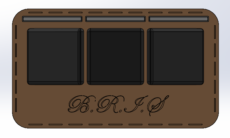
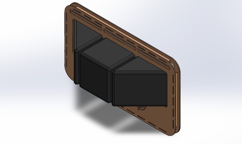
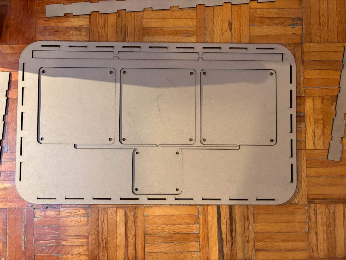
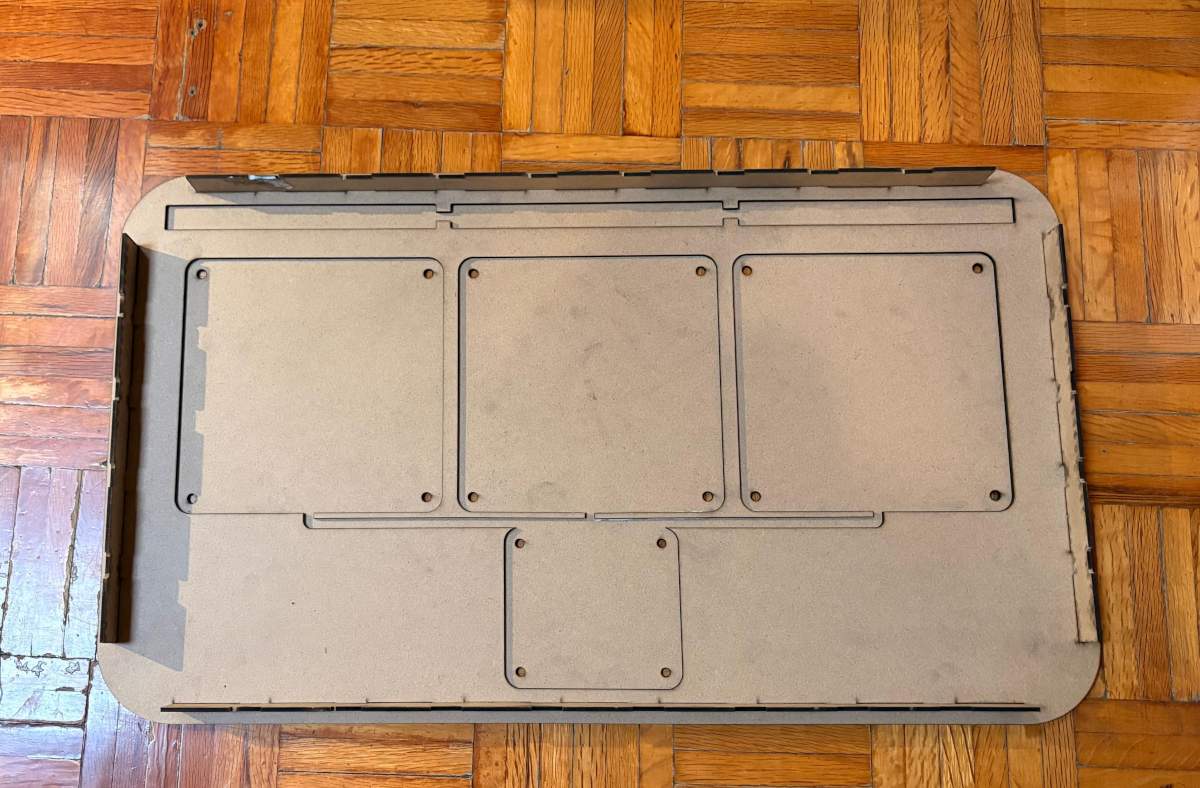
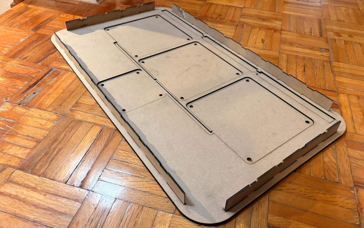
ASSEMBLY
Fabrication
Laser cutting
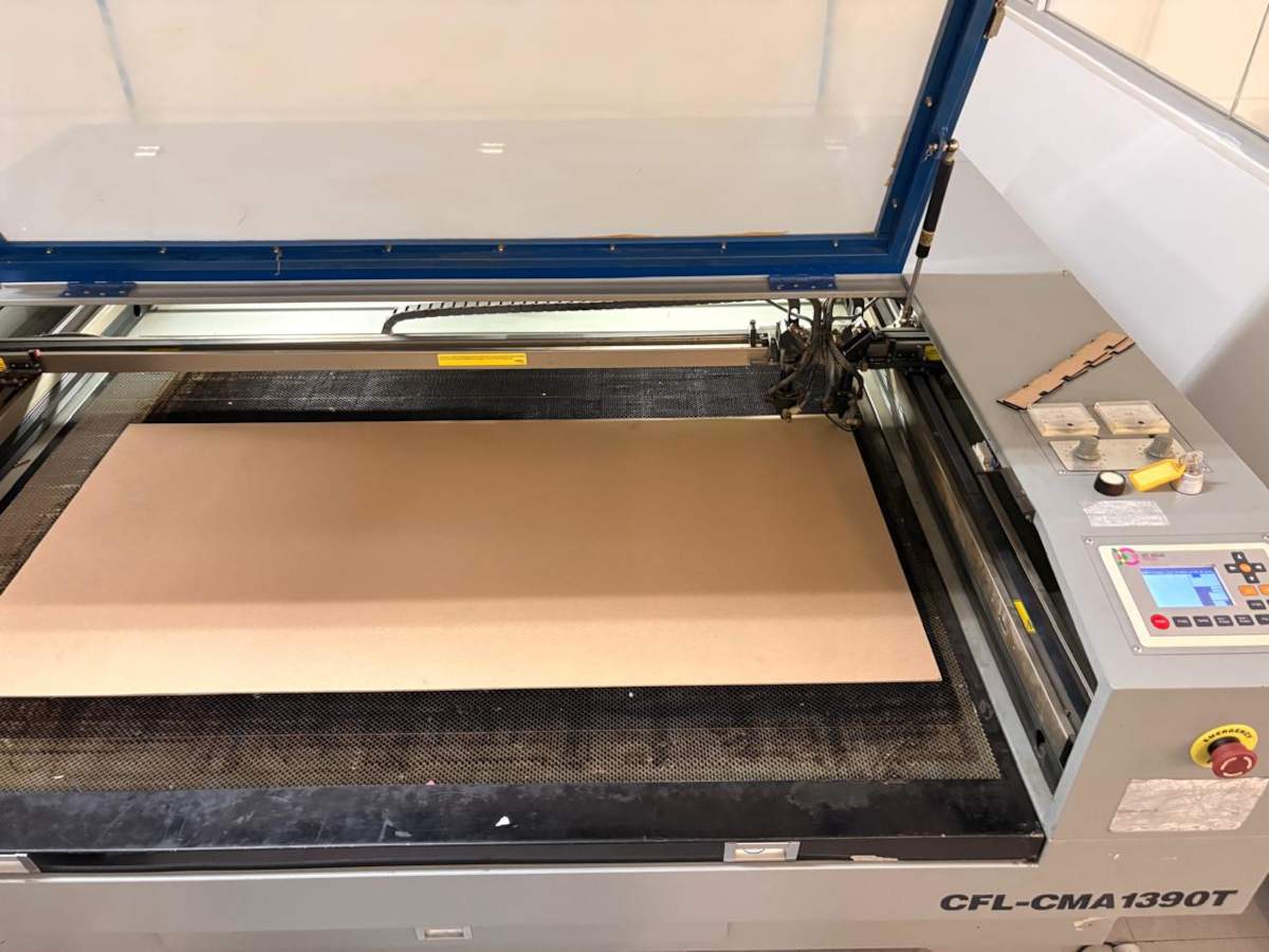
1. To cut we have to use the CFL_CMA1390T laser cutting machine, turn it on and place our material inside. For more information about the laser machine, go to my week 3.
Laser cutting
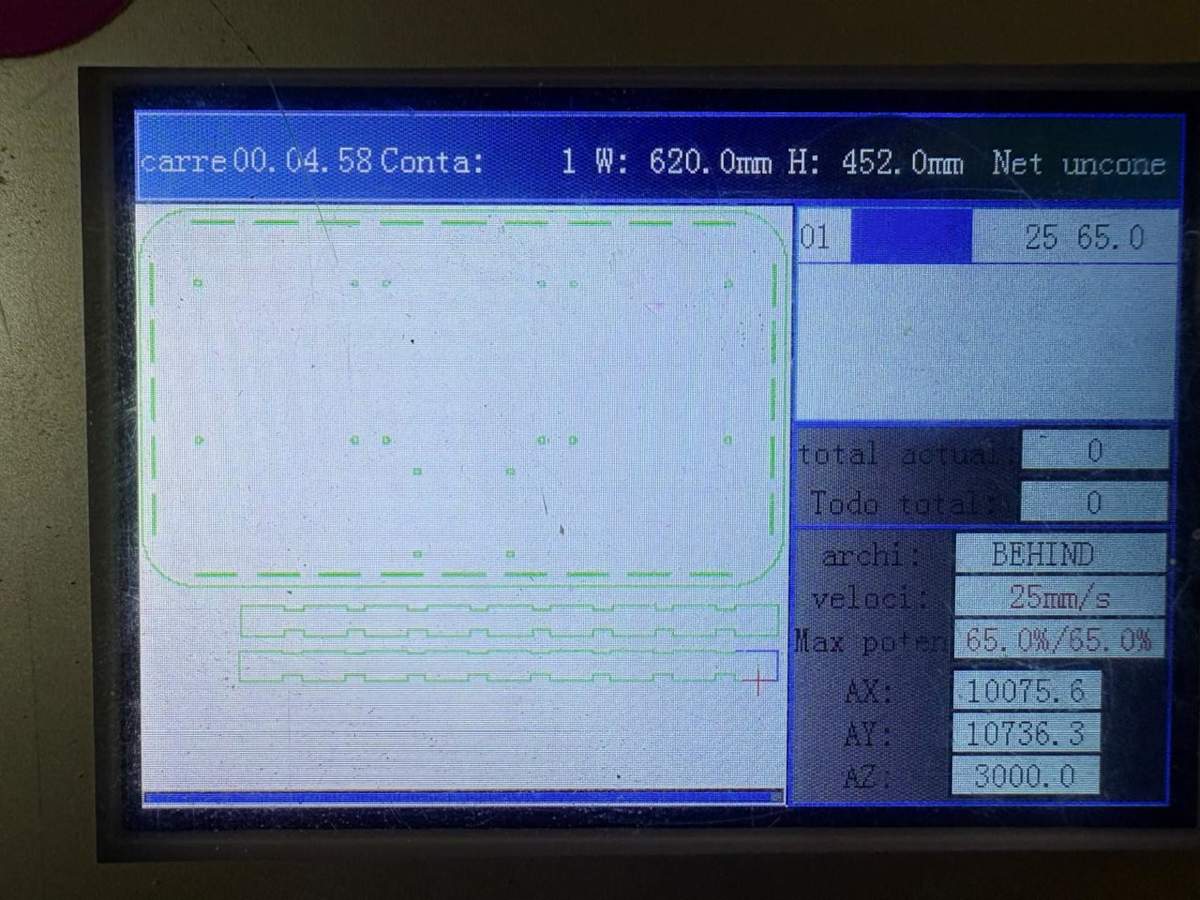
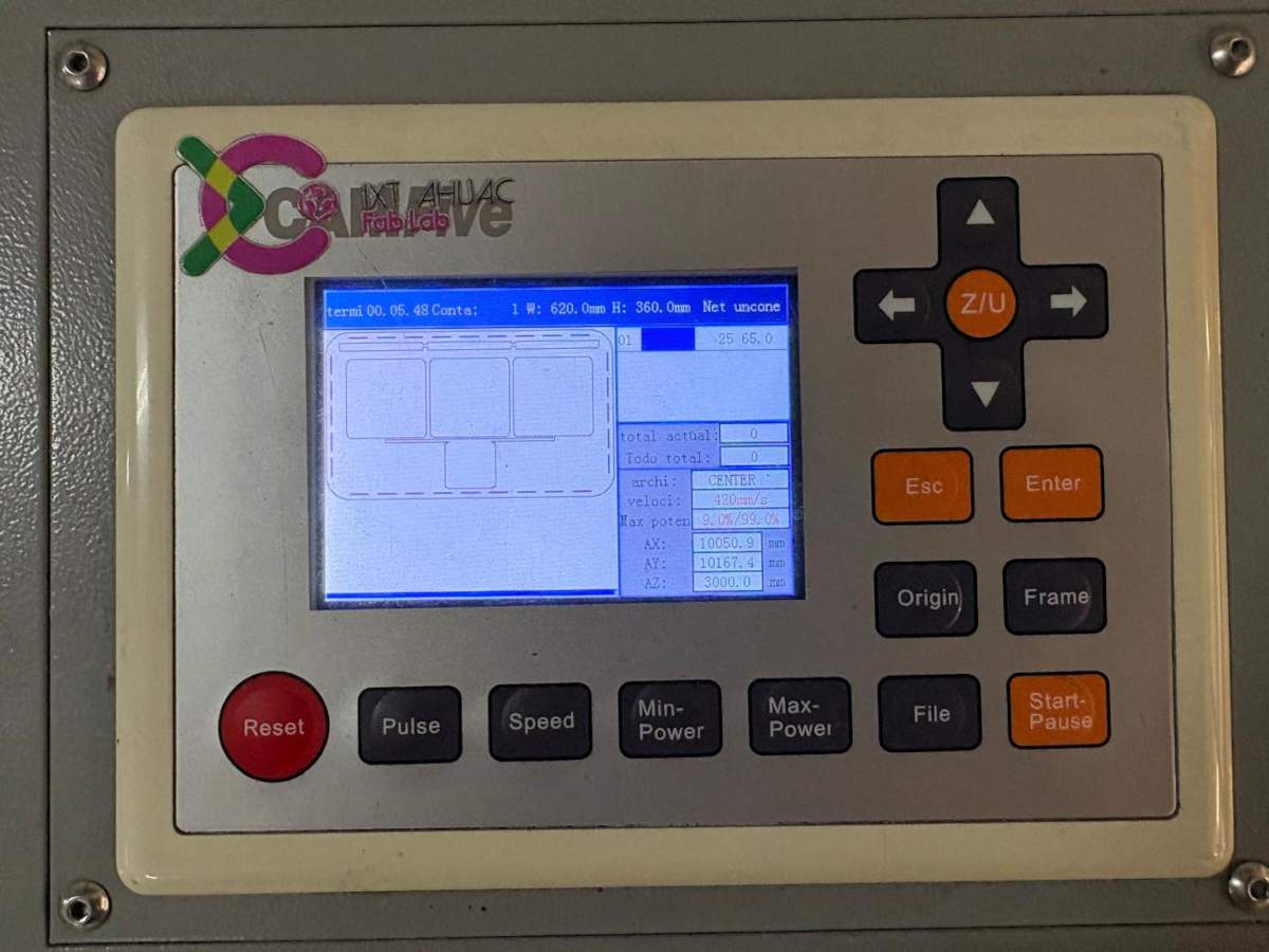
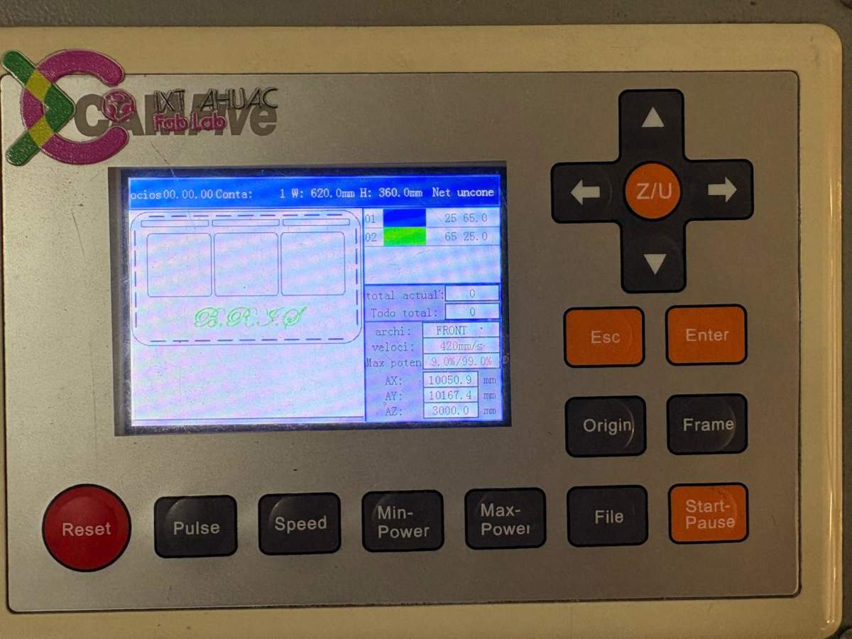
2. Then we set the parameters and then cut.
cut. Max. Power(%): 65, Min. Power(%): 60 and Work Speed (mm/s): 20.
Engrave. Max. Power(%): 25, Min. Power(%): 20 and Work Speed (mm/s): 200.
Results
 Cables & Attaching
Cables
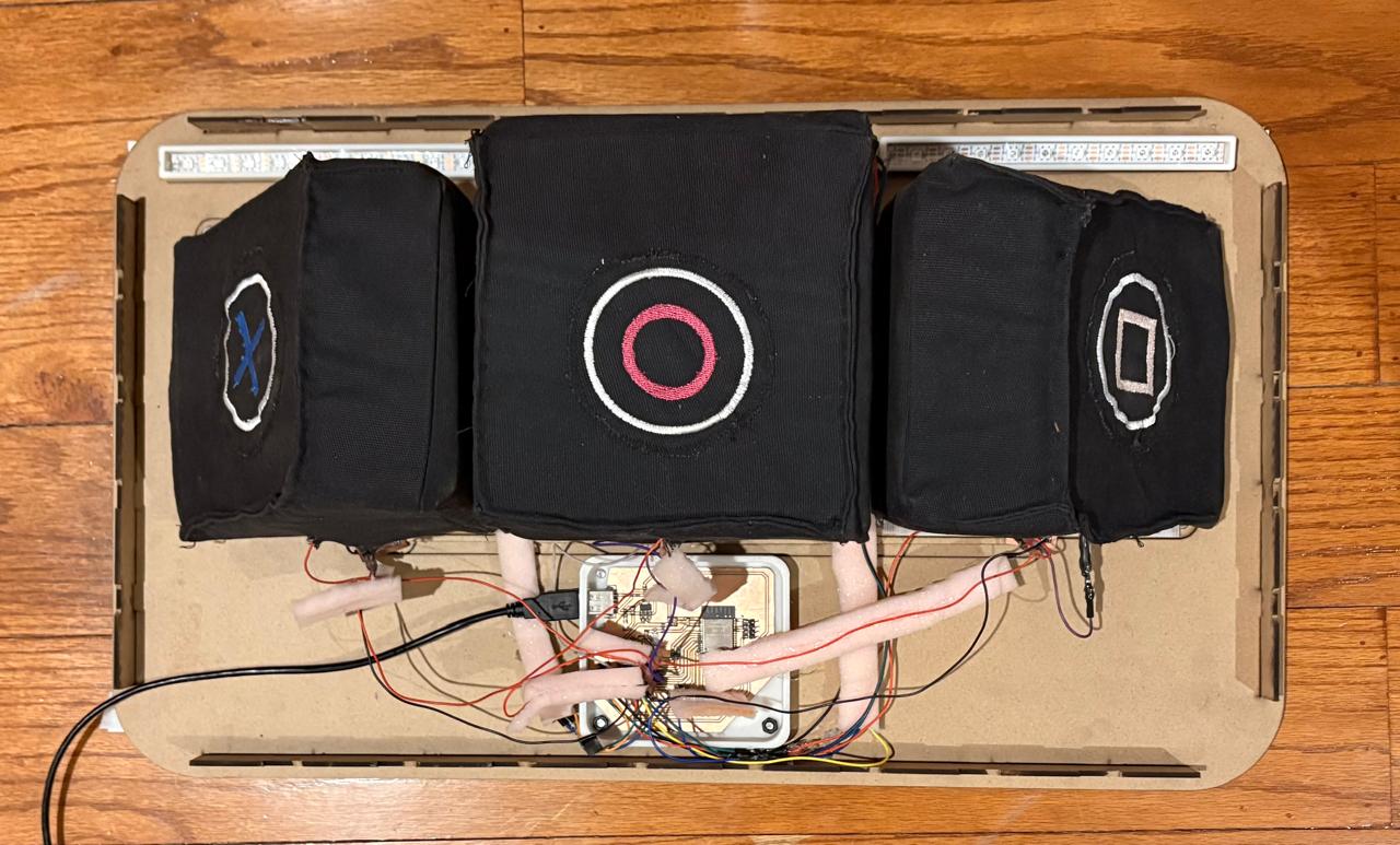
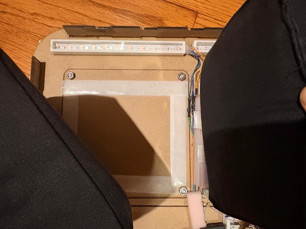
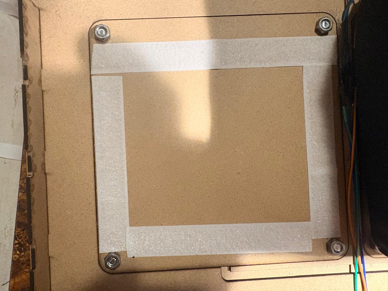
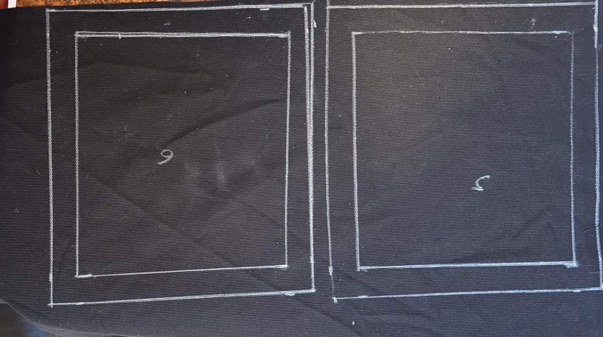
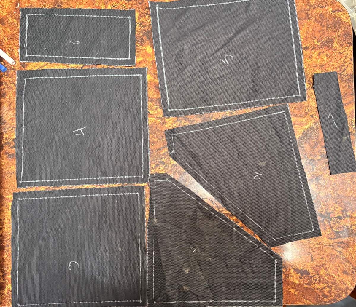
Cables.To route the wires, I had created a 3D model of my circuit boards to get an idea of how I was going to arrange them. Unfortunately, as the project progressed, I realized there was a lot of noise affecting my sensor readings, so I had to use some foam to space the wires apart and minimize the noise as much as possible; however, this solution didn’t give me a very clean result.
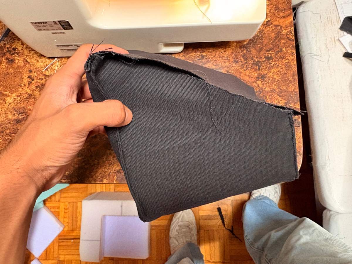
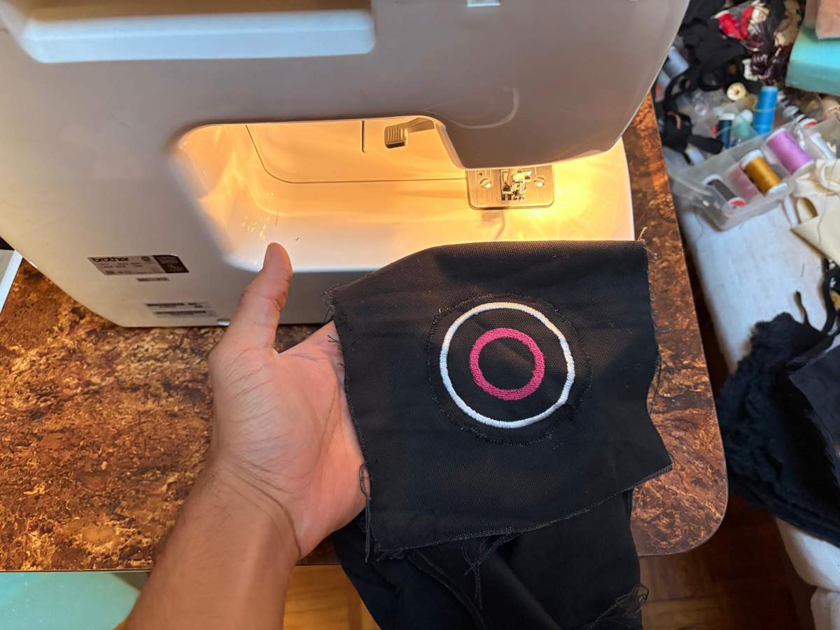
Attaching
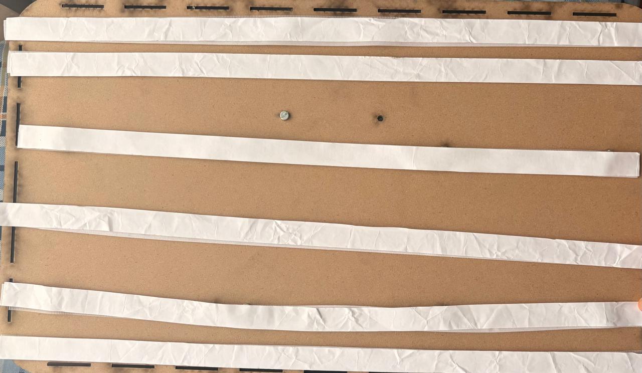
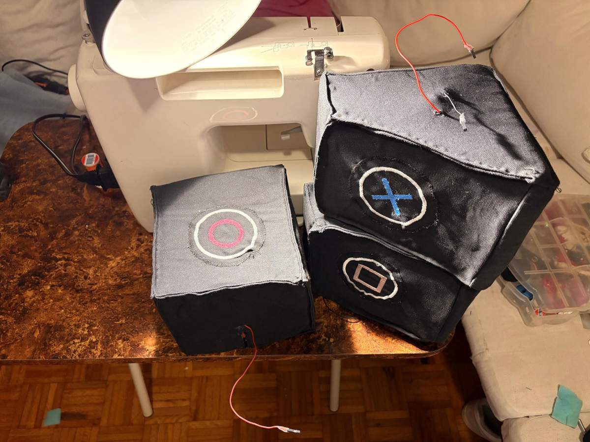
Attaching.To attach my pads, I cut the adhesive Velcro I had and placed it on the back of the pads, then attached the other side of the Velcro to the pads themselves. The result surprised me—it held quite firmly thanks to the excellent adhesive on the Velcro. I also used it to attach B.R.I.S. to the wall, and it worked just as well; it stayed firmly in place.
Final Thoughts
The development of B.R.I.S. was a challenge from multiple perspectives, including electronics production, mechanical design, system integration, and pad fabrication. The successful completion of this project was made possible largely through the knowledge acquired week by week throughout the course, as well as the support, guidance, and collaboration of my instructors and fellow students.
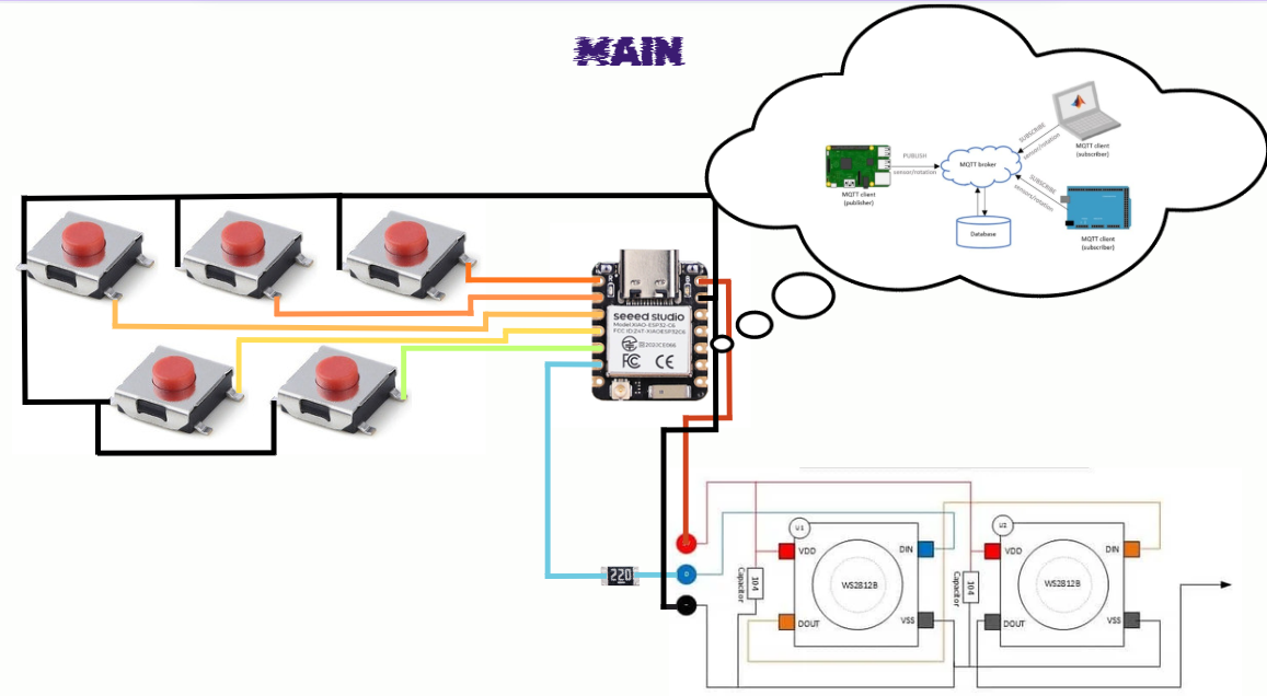
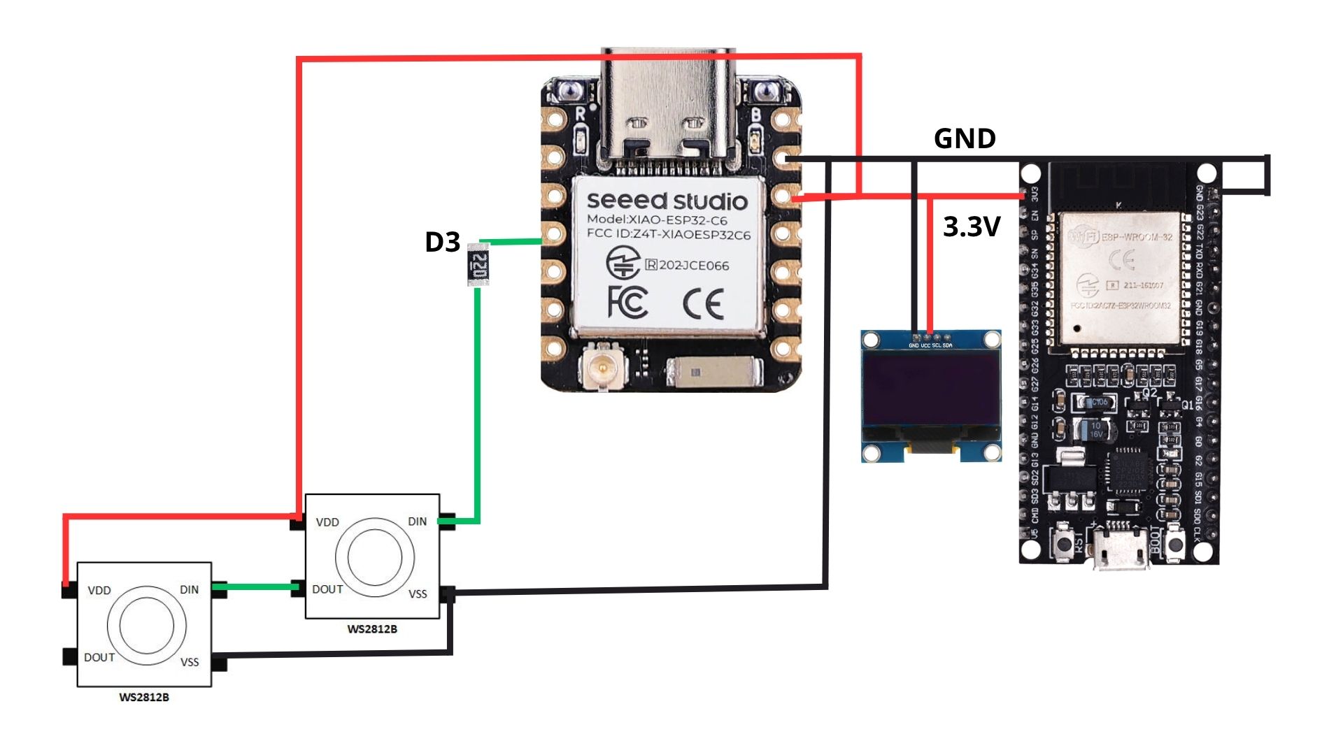
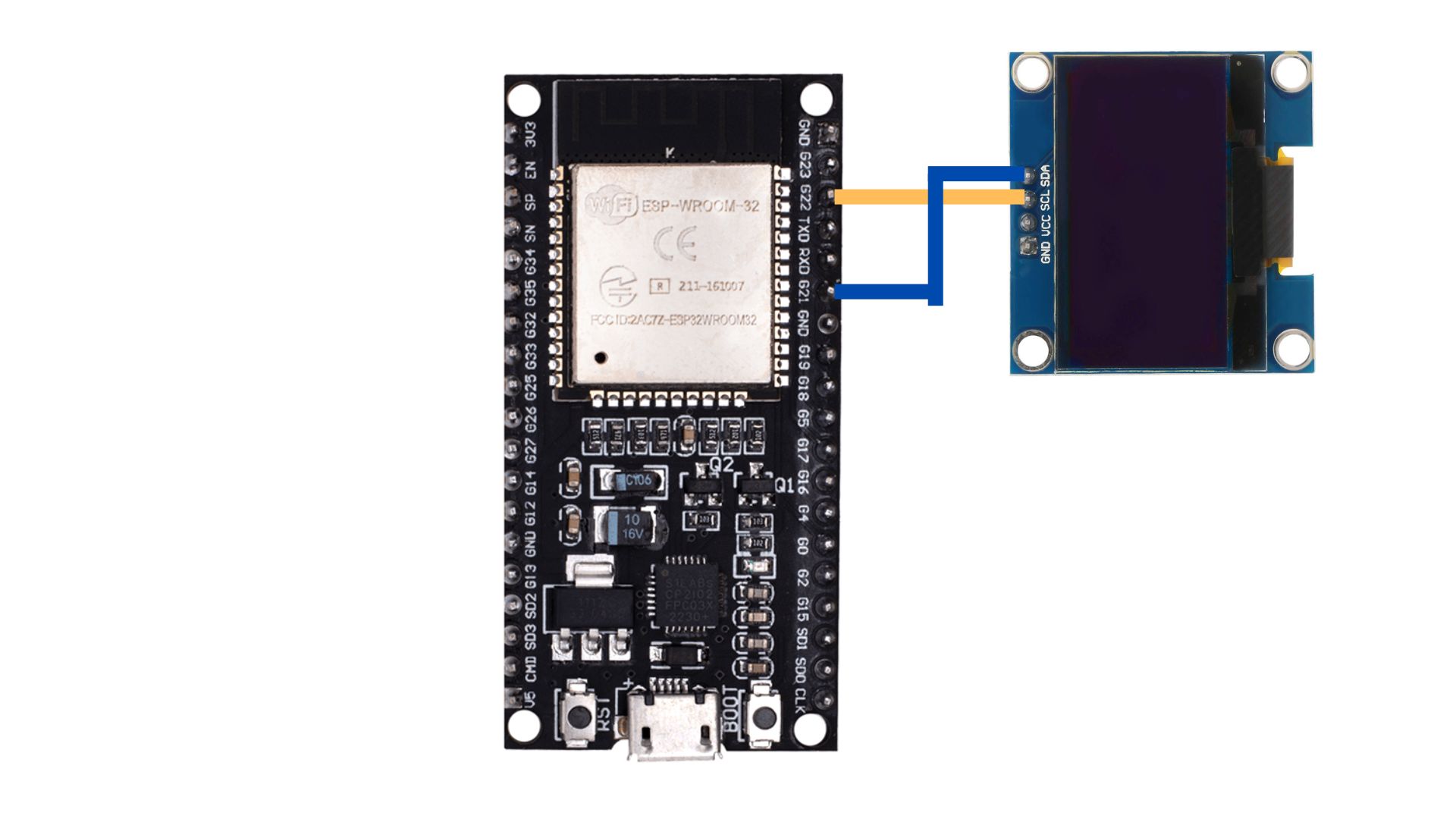
Personally, I consider the final result to be highly satisfactory because it fulfills the objectives that were originally proposed. The system is capable of detecting impacts, communicating data through MQTT, displaying information through a user interface, and providing visual feedback using Neopixels. Although the project achieved its primary goals, there are several aspects I would like to improve in future iterations. In particular, I would like to enhance the step-response sensors to obtain cleaner readings with less interference and greater reliability. I would also like to reinforce the structure with internal supports to better withstand repeated impacts and improve the overall durability of the device.
Another feature I would like to implement is impact force measurement. Unfortunately, I was unable to fully integrate this functionality due to challenges related to MQTT message transmission and system integration. Despite this limitation, the remaining components of the project performed reliably and met expectations.
I would like to express my sincere gratitude to my instructor Aristarco for his continuous support and guidance throughout the development of the project. I would also like to thank Oliver and the rest of my instructors for sharing their knowledge and helping me overcome technical challenges during the course. Finally, I would like to thank my classmates for their collaboration, encouragement, and presence throughout this learning experience.
B.R.I.S. is not only my final project; it is also a reflection of everything I learned during Fab Academy and a demonstration of the skills, knowledge, and confidence I developed throughout the program. It represents both the culmination of months of work and the foundation for future improvements and new ideas.
Files
B.R.I.S. INTERFACE
If you want to take a look at the interface click here B.R.I.S.
Integration & Packaging
Part Design & 3D Printing
NEOPIXELS case
1. First, I changed the document units to CGS and created a center point rectangle of 1.7 X 18 cm in the front plane.
NEOPIXELS case
2. Then, I extruded it 1.5 cm and made roundings of 0.20 cm.
NEOPIXELS case
3. After that, I made a plane 0.30 cm from the front face of the piece.
4. And in that plane made a rectangle with a distance of 0.30 cm from each edge. Then, I extruded a cut of 0.90 cm inside.
NEOPIXELS case
5. Subsequently, in the lateral face of the piece I made a rectangle of 1.10 X 0.50 cm at a distance of 0.30 cm from each edge. Next, I extruded a cut inside. I also added roundings in the corners so it could look better.
NEOPIXELS case
6. After that, I made a plane 0.90 cm from the back face of the piece.
7. Then I added a rectangle to create a tab where I could later insert a transparent sheet. Then, I extruded a cut of 0.10 cm inside and outside.
Results
~ Export. We have to export our piece as an STL so we can print it. For that, we must go to File, then look for Save as and save it as STL.
Printing
~ Slicer: To print, I used Prusa Slicer. I will also use a Prusa MK4S for the 3D printing process.
NEOPIXELS case
1. First, open the slicer and import the STL piece.
NEOPIXELS case
2. For importing, we have to press File, then import and select import STL.
NEOPIXELS case
3. After that, we have to set the printing parameters. Being honest, I just placed my piece on the center, changed the material to PLA and also changed the infill to 5%.
4. Then, we just have to press the button at the bottom labeled as SLICE.
5. Having sliced our piece, we can see the way it will be printed and, by pressing the button below, we can save it in the Prusa USB.
Results
System Integration
After week 15, I made changes to the structure to improve the assembly’s usability and durability, and also, to have a packaging for my project. Among the most significant changes are a reduction in the horizontal size, reduction in the space between the pads, engraving on the front panel, and fine-tuning of the screw sizes and spacing between components.
Position footprint
PIECE. First, I changed the document units to CGS and created a center point rectangle of 62 X 36 cm in the front plane. Then, I made fillets of 5 cm of diameter and extruded it 3 mm. Next, I traced the outlines of the parts I’ll be placing in the assembly, which are: 3 Neopixel casings, 3 pads, and the ESP32 casing. My pads will measure 17 x 17 cm, spaced 1 cm apart, with a 2 cm distance from their respective Neopixels and a 1 cm vertical distance from the center pad to the ESP32 housing. Then I extruded the cut. After that, I made small conduits of 6 mm to keep the wires from my components tidy. They all go to the ESP32. Finally, I made small joints around mi piece.
BASE
PIECE. First, I changed the document units to CGS and created a center point rectangle of 62 X 36 cm in the front plane. Then, I made fillets of 5 cm of diameter and extruded it 3 mm. After, I made small holes located in the corners of the Pads and the ESP32 case, to attach them to the board. Finally, I made small joints around my piece.
PAD BASE. Also create the bases for the pads; this is to provide them with better support. They measure 17 x 17 cm, with a 1-cm fillet, and have the same 6-mm holes 1 cm from the side and top edges.
WALLS
PIECE. The lateral wall design consists of 5 teeth at the top and bottom. The top teeth measure 4.02 × 0.3 cm and the bottom teeth 4.02 × 0.6 cm, taking into account the kerf and the fact that the bottom must fit into two layers 0.3 cm thick. I then extruded it by 0.3 cm. The design of the top and bottom walls consists of 9 teeth on each side. The top teeth measure 4.2 x 0.3 cm and the bottom teeth measure 4.2 x 0.6 cm, taking into account the kerf and the fact that the bottom section must fit into two layers, each 0.3 cm thick. I then extruded it by 0.3 cm.
FRONT FACE
PIECE. First, I changed the document units to CGS and created a center point rectangle of 62 X 36 cm in the front plane. Then, I made fillets of 5 cm of diameter and extruded it 3 mm. Next, I traced the outlines of the parts placed , which are: 3 Neopixel casings and 3 pads. My pads will measure 17 x 17 cm, spaced 1 cm apart, with a 2 cm distance from their respective Neopixels. In the space below, I wrote the name of the prject, which is B.R.I.S.
ASSEMBLY
Fabrication
Laser cutting
1. To cut we have to use the CFL_CMA1390T laser cutting machine, turn it on and place our material inside. For more information about the laser machine, go to my week 3.
Laser cutting
2. Then we set the parameters and then cut.
cut. Max. Power(%): 65, Min. Power(%): 60 and Work Speed (mm/s): 20.
Engrave. Max. Power(%): 25, Min. Power(%): 20 and Work Speed (mm/s): 200.
Results
Cables & Attaching
Cables
Cables.To route the wires, I had created a 3D model of my circuit boards to get an idea of how I was going to arrange them. Unfortunately, as the project progressed, I realized there was a lot of noise affecting my sensor readings, so I had to use some foam to space the wires apart and minimize the noise as much as possible; however, this solution didn’t give me a very clean result.
Attaching
Attaching.To attach my pads, I cut the adhesive Velcro I had and placed it on the back of the pads, then attached the other side of the Velcro to the pads themselves. The result surprised me—it held quite firmly thanks to the excellent adhesive on the Velcro. I also used it to attach B.R.I.S. to the wall, and it worked just as well; it stayed firmly in place.
Final Thoughts
The development of B.R.I.S. was a challenge from multiple perspectives, including electronics production, mechanical design, system integration, and pad fabrication. The successful completion of this project was made possible largely through the knowledge acquired week by week throughout the course, as well as the support, guidance, and collaboration of my instructors and fellow students.
Personally, I consider the final result to be highly satisfactory because it fulfills the objectives that were originally proposed. The system is capable of detecting impacts, communicating data through MQTT, displaying information through a user interface, and providing visual feedback using Neopixels. Although the project achieved its primary goals, there are several aspects I would like to improve in future iterations. In particular, I would like to enhance the step-response sensors to obtain cleaner readings with less interference and greater reliability. I would also like to reinforce the structure with internal supports to better withstand repeated impacts and improve the overall durability of the device.
Another feature I would like to implement is impact force measurement. Unfortunately, I was unable to fully integrate this functionality due to challenges related to MQTT message transmission and system integration. Despite this limitation, the remaining components of the project performed reliably and met expectations.
I would like to express my sincere gratitude to my instructor Aristarco for his continuous support and guidance throughout the development of the project. I would also like to thank Oliver and the rest of my instructors for sharing their knowledge and helping me overcome technical challenges during the course. Finally, I would like to thank my classmates for their collaboration, encouragement, and presence throughout this learning experience.
B.R.I.S. is not only my final project; it is also a reflection of everything I learned during Fab Academy and a demonstration of the skills, knowledge, and confidence I developed throughout the program. It represents both the culmination of months of work and the foundation for future improvements and new ideas.
Files
NEOPIXELS case
1. First, I changed the document units to CGS and created a center point rectangle of 1.7 X 18 cm in the front plane.
NEOPIXELS case
2. Then, I extruded it 1.5 cm and made roundings of 0.20 cm.
NEOPIXELS case
3. After that, I made a plane 0.30 cm from the front face of the piece.
4. And in that plane made a rectangle with a distance of 0.30 cm from each edge. Then, I extruded a cut of 0.90 cm inside.
NEOPIXELS case
5. Subsequently, in the lateral face of the piece I made a rectangle of 1.10 X 0.50 cm at a distance of 0.30 cm from each edge. Next, I extruded a cut inside. I also added roundings in the corners so it could look better.
NEOPIXELS case
6. After that, I made a plane 0.90 cm from the back face of the piece.
7. Then I added a rectangle to create a tab where I could later insert a transparent sheet. Then, I extruded a cut of 0.10 cm inside and outside.
Results
~ Export. We have to export our piece as an STL so we can print it. For that, we must go to File, then look for Save as and save it as STL.
Printing
~ Slicer: To print, I used Prusa Slicer. I will also use a Prusa MK4S for the 3D printing process.
NEOPIXELS case
1. First, open the slicer and import the STL piece.
NEOPIXELS case
2. For importing, we have to press File, then import and select import STL.
NEOPIXELS case
3. After that, we have to set the printing parameters. Being honest, I just placed my piece on the center, changed the material to PLA and also changed the infill to 5%.
4. Then, we just have to press the button at the bottom labeled as SLICE.
5. Having sliced our piece, we can see the way it will be printed and, by pressing the button below, we can save it in the Prusa USB.
Results
Position footprint
PIECE. First, I changed the document units to CGS and created a center point rectangle of 62 X 36 cm in the front plane. Then, I made fillets of 5 cm of diameter and extruded it 3 mm. Next, I traced the outlines of the parts I’ll be placing in the assembly, which are: 3 Neopixel casings, 3 pads, and the ESP32 casing. My pads will measure 17 x 17 cm, spaced 1 cm apart, with a 2 cm distance from their respective Neopixels and a 1 cm vertical distance from the center pad to the ESP32 housing. Then I extruded the cut. After that, I made small conduits of 6 mm to keep the wires from my components tidy. They all go to the ESP32. Finally, I made small joints around mi piece.
BASE
PIECE. First, I changed the document units to CGS and created a center point rectangle of 62 X 36 cm in the front plane. Then, I made fillets of 5 cm of diameter and extruded it 3 mm. After, I made small holes located in the corners of the Pads and the ESP32 case, to attach them to the board. Finally, I made small joints around my piece.
PAD BASE. Also create the bases for the pads; this is to provide them with better support. They measure 17 x 17 cm, with a 1-cm fillet, and have the same 6-mm holes 1 cm from the side and top edges.
WALLS
PIECE. The lateral wall design consists of 5 teeth at the top and bottom. The top teeth measure 4.02 × 0.3 cm and the bottom teeth 4.02 × 0.6 cm, taking into account the kerf and the fact that the bottom must fit into two layers 0.3 cm thick. I then extruded it by 0.3 cm. The design of the top and bottom walls consists of 9 teeth on each side. The top teeth measure 4.2 x 0.3 cm and the bottom teeth measure 4.2 x 0.6 cm, taking into account the kerf and the fact that the bottom section must fit into two layers, each 0.3 cm thick. I then extruded it by 0.3 cm.
FRONT FACE
PIECE. First, I changed the document units to CGS and created a center point rectangle of 62 X 36 cm in the front plane. Then, I made fillets of 5 cm of diameter and extruded it 3 mm. Next, I traced the outlines of the parts placed , which are: 3 Neopixel casings and 3 pads. My pads will measure 17 x 17 cm, spaced 1 cm apart, with a 2 cm distance from their respective Neopixels. In the space below, I wrote the name of the prject, which is B.R.I.S.
ASSEMBLY
Laser cutting
1. To cut we have to use the CFL_CMA1390T laser cutting machine, turn it on and place our material inside. For more information about the laser machine, go to my week 3.
Laser cutting
2. Then we set the parameters and then cut.
cut. Max. Power(%): 65, Min. Power(%): 60 and Work Speed (mm/s): 20.
Engrave. Max. Power(%): 25, Min. Power(%): 20 and Work Speed (mm/s): 200.
Results
Cables
Cables.To route the wires, I had created a 3D model of my circuit boards to get an idea of how I was going to arrange them. Unfortunately, as the project progressed, I realized there was a lot of noise affecting my sensor readings, so I had to use some foam to space the wires apart and minimize the noise as much as possible; however, this solution didn’t give me a very clean result.
Attaching
Attaching.To attach my pads, I cut the adhesive Velcro I had and placed it on the back of the pads, then attached the other side of the Velcro to the pads themselves. The result surprised me—it held quite firmly thanks to the excellent adhesive on the Velcro. I also used it to attach B.R.I.S. to the wall, and it worked just as well; it stayed firmly in place.

Final Thoughts
The development of B.R.I.S. was a challenge from multiple perspectives, including electronics production, mechanical design, system integration, and pad fabrication. The successful completion of this project was made possible largely through the knowledge acquired week by week throughout the course, as well as the support, guidance, and collaboration of my instructors and fellow students.Personally, I consider the final result to be highly satisfactory because it fulfills the objectives that were originally proposed. The system is capable of detecting impacts, communicating data through MQTT, displaying information through a user interface, and providing visual feedback using Neopixels. Although the project achieved its primary goals, there are several aspects I would like to improve in future iterations. In particular, I would like to enhance the step-response sensors to obtain cleaner readings with less interference and greater reliability. I would also like to reinforce the structure with internal supports to better withstand repeated impacts and improve the overall durability of the device.
Another feature I would like to implement is impact force measurement. Unfortunately, I was unable to fully integrate this functionality due to challenges related to MQTT message transmission and system integration. Despite this limitation, the remaining components of the project performed reliably and met expectations.
I would like to express my sincere gratitude to my instructor Aristarco for his continuous support and guidance throughout the development of the project. I would also like to thank Oliver and the rest of my instructors for sharing their knowledge and helping me overcome technical challenges during the course. Finally, I would like to thank my classmates for their collaboration, encouragement, and presence throughout this learning experience.
B.R.I.S. is not only my final project; it is also a reflection of everything I learned during Fab Academy and a demonstration of the skills, knowledge, and confidence I developed throughout the program. It represents both the culmination of months of work and the foundation for future improvements and new ideas.