WEEK 14

TASK
MONDAY
WEDNESDAY
FRIDAY
MONDAY

✦ Interface and Application Programming

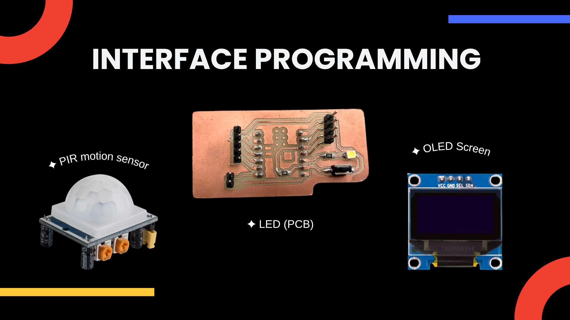
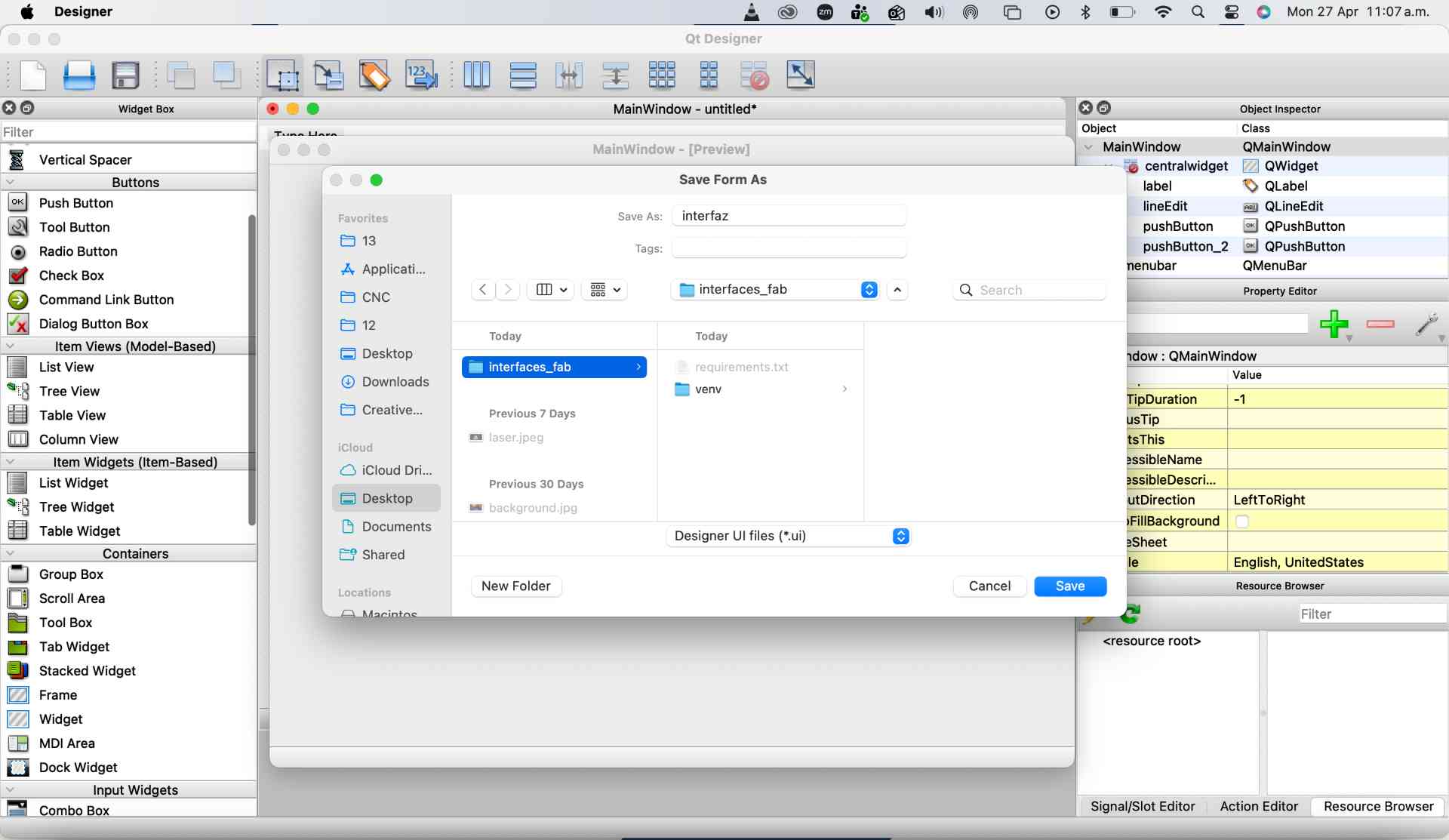
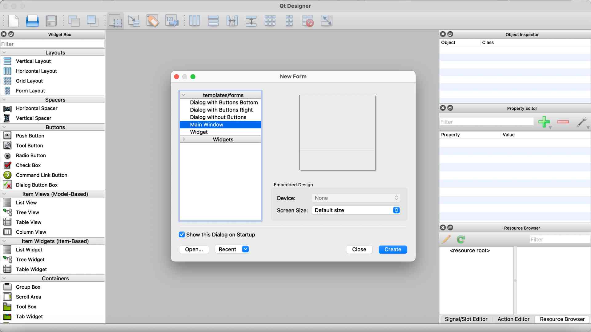
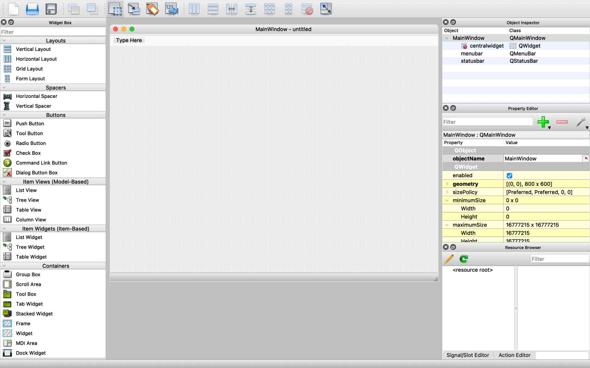
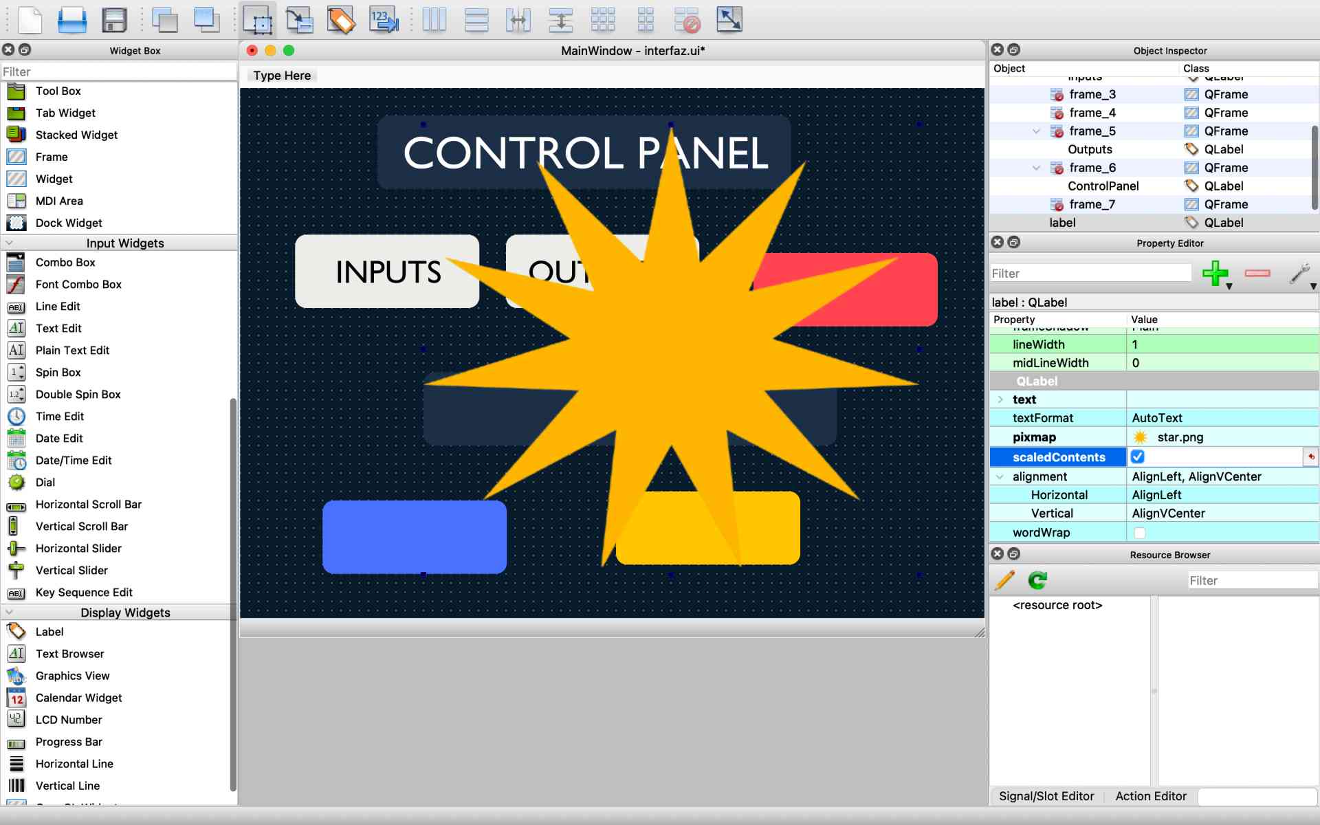
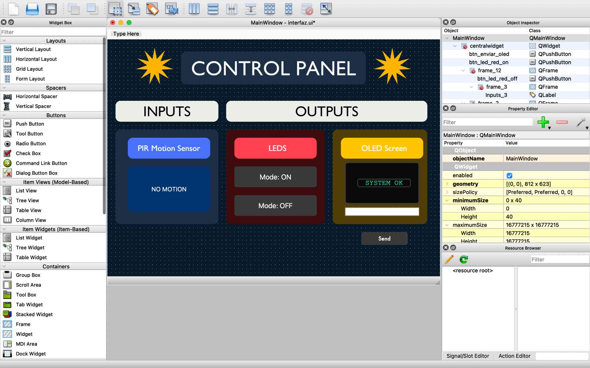
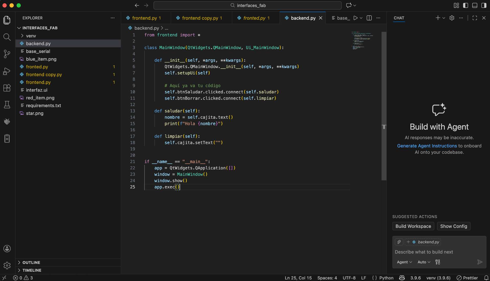
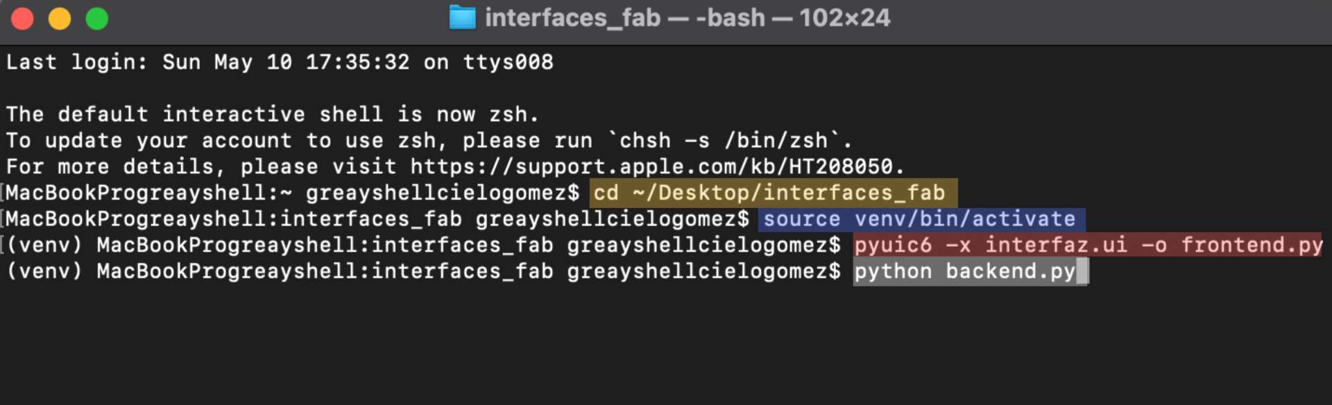
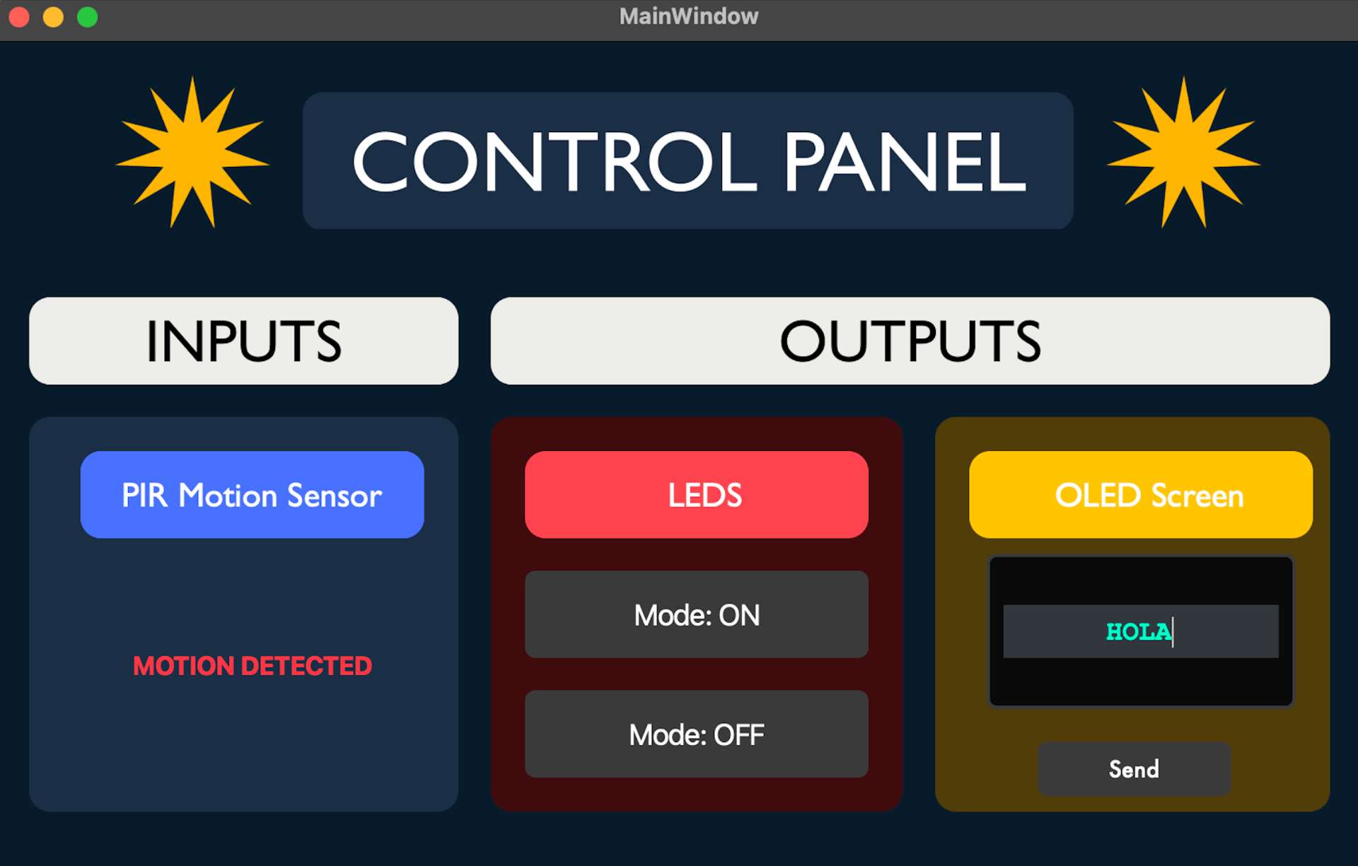
For this week, I developed a custom control panel using Python and Qt Designer to interact with my Seeed XIAO ESP32-C6 board that I designed in Week 11. The interface was designed to read input data from a PIR motion sensor and control different outputs, including a LED and an OLED screen. The goal was to create a visual interface that could communicate with the physical circuit through serial communication, allowing the computer and the microcontroller to exchange information in real time. For this week I will be consulting our Group Assignment.

✦ System Overview

The system was divided into two main parts: inputs and outputs. The input section reads the state of the PIR motion sensor and displays whether motion is detected. The output section allows the user to turn the PCB LED on or off and send a custom text message to the OLED screen.

Pinout Diagram

✦ Interface Design

I created the interface in Qt Designer, a visual interface editor for Python applications. It is important to create a dedicated folder to keep all the interface files organized, including the .ui file, Python scripts, images, assets and virtual environment.

QFrame {
    background-color: #5170ff;
    border-radius: 12px;
    border: none;
    padding: 15px;
}
   // Change Stylesheet Example 

✦ Visual Studio Code

A new project workspace was created in Visual Studio Code, where the main files for the interface were organized. The project included the interfaz.ui file from Qt Designer, the generated frontend.py file for the graphical interface, and the backend.py file, where the main programming logic and serial communication with the XIAO ESP32-C6 were developed.

Pinout Diagram

✦ Running the Interface

After finishing the design, the .ui file was converted into Python code using the terminal:

Pinout Diagram

✦ Commands

Sequence of terminal commands used to activate the environment, convert the Qt interface into Python and run the backend application.

cd ~/Desktop/interfaces_fab    // Opens the project folder
source venv/bin/activate    // Activates the virtual environment
pyuic6 -x interfaz.ui -o frontend.py    // Converts Qt Designer into Python
python backend.py    // Runs the backend program

✦ Final Interface

This is the final interface window that automatically opens after running the backend program from the terminal, allowing real-time interaction with the PCB.

Pinout Diagram

✦ ARDUINO IDE

The code was uploaded using Arduino IDE after selecting the Seeed XIAO ESP32-C6 board and the correct serial port. Once configured, the program was compiled and uploaded to the PCB. For a more detailed explanation of the upload process, refer to Week 11. Also I installed the libraries: Adafruit GFX Library and Adafruit SH110X.


#include < SPI.h >
#include < Wire.h>
#include < Adafruit_GFX.h>
#include < Adafruit_SH110X.h>

// I initialized the 128x64 OLED display using the I2C protocol structure
Adafruit_SH1106G display = Adafruit_SH1106G(128, 64, &Wire, -1);

// Hardware pin mapping for my custom PCB routing
const int LED_PIN = D9;      // Actuator output pin
const int PIR_PIN = D10;     // Sensor input pin

int lastPirState = LOW;      // I stored the previous state to filter redundant serial logs

void setup() {
    // I opened the serial channel at 115200 bps to synchronize with my Python GUI
    Serial.begin(115200);
    
    // I configured the data direction for my digital pins
    pinMode(LED_PIN, OUTPUT);
    pinMode(PIR_PIN, INPUT); 
    
    // I forced a low state to guarantee the LED starts completely turned off
    digitalWrite(LED_PIN, LOW); 

    // I mounted the OLED using its default 0x3C I2C address and printed a boot message
    display.begin(0x3C, true); 
    display.clearDisplay();
    display.setTextSize(1);
    display.setTextColor(SH110X_WHITE);
    display.setCursor(0, 0);
    display.print("System Ready...");
    display.display();
}

void loop() {
    // --- TASK 1: REAL-TIME SENSOR SAMPLING ---
    int currentPirState = digitalRead(PIR_PIN);

    // I implemented state-change detection to prevent flooding the USB buffer
    if (currentPirState != lastPirState) {
        if (currentPirState == HIGH) {
            Serial.println("MOTION_DETECTED");
        } else {
            Serial.println("NO_MOTION");
        }
        lastPirState = currentPirState; // I updated the history register
    }

    // --- TASK 2: SERIAL COMMAND PARSING ---
    if (Serial.available() > 0) {
        // I captured incoming strings up to the newline delimiter
        String command = Serial.readStringUntil('\n');
        command.trim(); // I stripped any residual whitespaces

        // I isolated incoming text payloads targeting the OLED screen
        if (command.startsWith("TXT:")) {
            String mensaje = command.substring(4); // I trimmed the prefix token
            display.clearDisplay();
            display.setCursor(0, 10);
            display.setTextSize(2); // Set to size 2 for better UI scanning
            display.print(mensaje);
            display.display();
        } 
        // Discrete commands received from the Python interface buttons
        else if (command == "RED_ON") {
            digitalWrite(LED_PIN, HIGH);
        } 
        else if (command == "RED_OFF") {
            digitalWrite(LED_PIN, LOW);
        }
    }
    
    delay(20); // I added a 20ms threshold to stabilize the execution loop
}
    
Pinout Diagram

✦ COMMANDS USED (C++)

Command
Description
Serial.begin(115200)
Opens serial communication between the XIAO ESP32-C6 and the Python interface.
pinMode(LED_PIN, OUTPUT)
Configures the LED pin as an output.
pinMode(PIR_PIN, INPUT)
Configures the PIR sensor pin as an input.
digitalRead(PIR_PIN)
Reads the current state of the motion sensor.
display.begin(0x3C, true)
Initializes the OLED display using I2C address.
display.print()
Sends text to the OLED screen.
Serial.println()
Sends sensor status messages to the Python.
command.startsWith("TXT:")
Detects text commands sent from the interface.
delay(20)
Stabilizes the execution loop with a short delay.
digitalWrite(LED_PIN, HIGH/LOW)
Turns the LED ON or OFF.

✦ PYTHON CODE

The Python backend code was written directly in Visual Studio Code inside the backend.py file, where the serial communication, interface logic, and interaction with the PCB were programmed.


import sys
import serial
from PyQt6 import QtWidgets, QtCore
from frontend import Ui_MainWindow  

class MainWindow(QtWidgets.QMainWindow, Ui_MainWindow):
    def __init__(self):
        super().__init__()
        self.setupUi(self)
        
        # I established the USB serial link at 115200 bps matching the microcontroller configuration
        try:
            self.serial_port = serial.Serial('/dev/cu.usbmodem101', 115200, timeout=1)
            print("Serial Connection Established Successfully!")
        except Exception as e:
            print(f"Error al conectar con la placa: {e}")

        # I mapped the interface button interaction signals to their respective handler functions
        self.btn_led_red_on.clicked.connect(self.turn_led_on)
        self.btn_led_red_off.clicked.connect(self.turn_led_off)
        
        # I linked the click event of the submit button to route the text inputs toward the OLED
        self.btn_enviar_oled.clicked.connect(self.enviar_a_oled)

        # I configured a non-blocking background background timer running on a 100ms cycle
        self.timer = QtCore.QTimer()
        self.timer.setInterval(100) 
        self.timer.timeout.connect(self.read_serial_data)
        self.timer.start()

    # I transmitted the activation instruction payload encoded as raw bytes
    def turn_led_on(self):
        if hasattr(self, 'serial_port') and self.serial_port.isOpen():
            self.serial_port.write(b"RED_ON\n")
            print("Serial Data Sent: RED_ON")

    # I transmitted the deactivation instruction payload encoded as raw bytes
    def turn_led_off(self):
        if hasattr(self, 'serial_port') and self.serial_port.isOpen():
            self.serial_port.write(b"RED_OFF\n")
            print("Serial Data Sent: RED_OFF")

    # I captured the dynamic text string from the input widget and sent it with the control prefix token
    def enviar_a_oled(self):
        texto = self.oled_screen.text()
        if texto and hasattr(self, 'serial_port') and self.serial_port.isOpen():
            comando = f"TXT:{texto}\n"
            self.serial_port.write(comando.encode())
            print(f"Serial Data Sent: TXT:{texto}")

    # I continuously polled the hardware buffer data stream to catch incoming sensor triggers
    def read_serial_data(self):
        if hasattr(self, 'serial_port') and self.serial_port.isOpen():
            if self.serial_port.in_waiting > 0:
                try:
                    # I intercepted the line string data and translated the bytes back to text characters
                    data = self.serial_port.readline().decode('utf-8').strip()
                    
                    # I evaluated the data packet strings and updated the CSS style sheet parameters dynamically
                    if data == "MOTION_DETECTED":
                        self.lbl_movimiento.setText("MOTION DETECTED")
                        self.lbl_movimiento.setStyleSheet("color: #ff4d4d; font-weight: bold;") 
                    elif data == "NO_MOTION":
                        self.lbl_movimiento.setText("NO MOTION")
                        self.lbl_movimiento.setStyleSheet("color: #ffffff;") 
                except Exception as e:
                    print(f"Error leyendo serial: {e}")

    # I added a safe termination function to release the USB hardware resource when the application closes
    def closeEvent(self, event):
        if hasattr(self, 'serial_port') and self.serial_port.isOpen():
            self.serial_port.close()
        event.accept()

if __name__ == "__main__":
    app = QtWidgets.QApplication(sys.argv)
    window = MainWindow()
    window.show()
    sys.exit(app.exec())
    

✦ COMMANDS USED (C++)

Command
Description
serial.Serial('/dev/cu.usbmodem101', 115200)
Links interface buttons to their functions.
QtCore.QTimer()
Creates a background timer for continuous serial monitoring.
timer.setInterval(100)
Sets the timer update interval to 100 ms.
serial_port.write()
Sends commands from the Python GUI to the XIAO.
oled_screen.text()
Reads the text written inside the OLED input field.
comando.encode()
Converts the text command into byte format for serial transmission.
serial_port.readline().decode()
Reads and decodes incoming serial data from the PCB.
setText()
Updates the motion status text displayed in the interface.
setStyleSheet()
Dynamically changes the label colors.
window.show()
Launches & displays the interface window.
serial_port.close()
Safely closes the serial connection when the application exits.

✦ Final Result

Once the codes are loaded into both programs, we must open the terminal and enter the four commands, and our interface is ready to use.

✦ Download Here!

In this section, you can find the downloadable source files developed during this week.

ZIP

ARDUINO + Qt DESIGNER

Download Files