For this week's assignment, I integrated a servomotor into my star-shaped PCB I made in Week 8, controlled by a Seeed Studio XIAO RP2350. The goal was to incorporate an output device to my board and program it to perform a specific action.
Also, for this week I will be consulting our Group Assignment.
✦ Understanding Output Devices
An output device is a component that converts electrical signals from a microcontroller into a physical response.
These responses can take different forms depending on the type of device used. Unlike input devices, which capture
external data, outputs act as the system’s response mechanism, making responses visible, audible,
or tangible for the user.
✦ Types of System Responses
Output devices can generate different types of responses depending on the form of feedback they provide to the user.
2. Auditory Outputs: Buzzers or speakers (sound generation).
3. Mechanical Outputs:Motors or actuators (movement).
✦ Types of Signals
Also, output signals can be classified based on how they control device behavior.
Feauture
Description
Digital Outputs
Operate with two states (HIGH/LOW). Example: turning an LED on or off.
Analog Outputs (PWM)
Simulate variable signals by modulating pulse width, allowing control the intensity (LED brightness or motor speed).
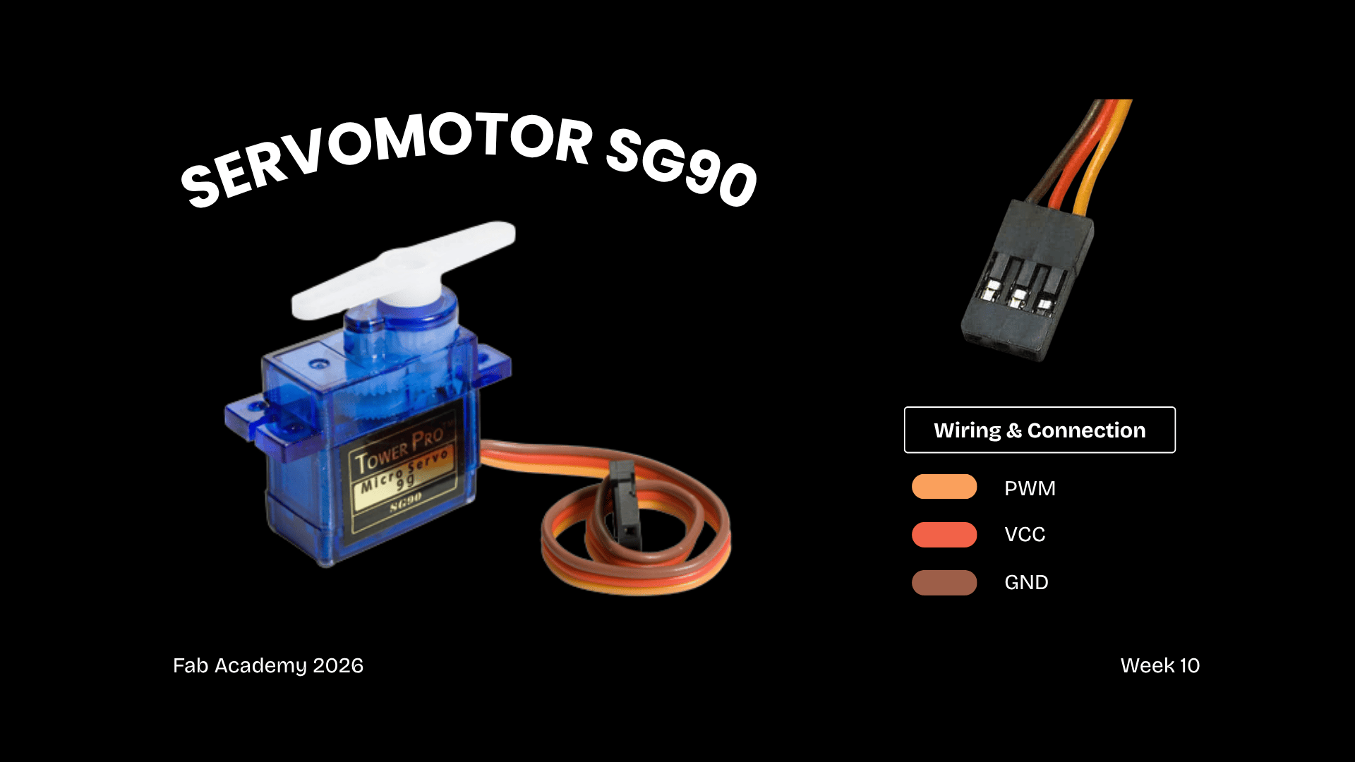
✦ Servomotor SG90
For this assignment, I decided to implement a servomotor as the output device in my PCB. Also, it’s important to know that a servomotor is a device that translates digital signals into angular movement and that allows precise control.
◆ Connections
1. VCC:Power supply (5V)
2. GND: Ground
3. SIGNAL: PWM control pin from the microcontroller (D6)
✦ Type of Signal: Digital Control (PWM)
Although servomotors are controlled through a digital pin, they operate using a Pulse Width Modulation (PWM) to simulate an analog behavior; this allows a precise angle control (typically between 0º and 180º) instead of simple ON/OFF states.
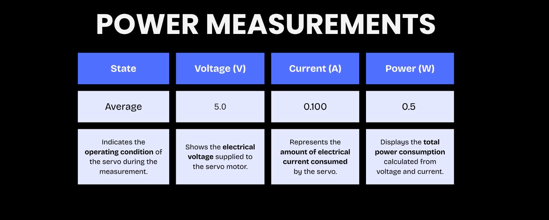
✦ Servo Power Measurements
This section documents the electrical measurements of the SG90 servo motor during operation, including voltage, current consumption, and power usage to better understand its performance and energy requirements. For more information consult our Group Page.
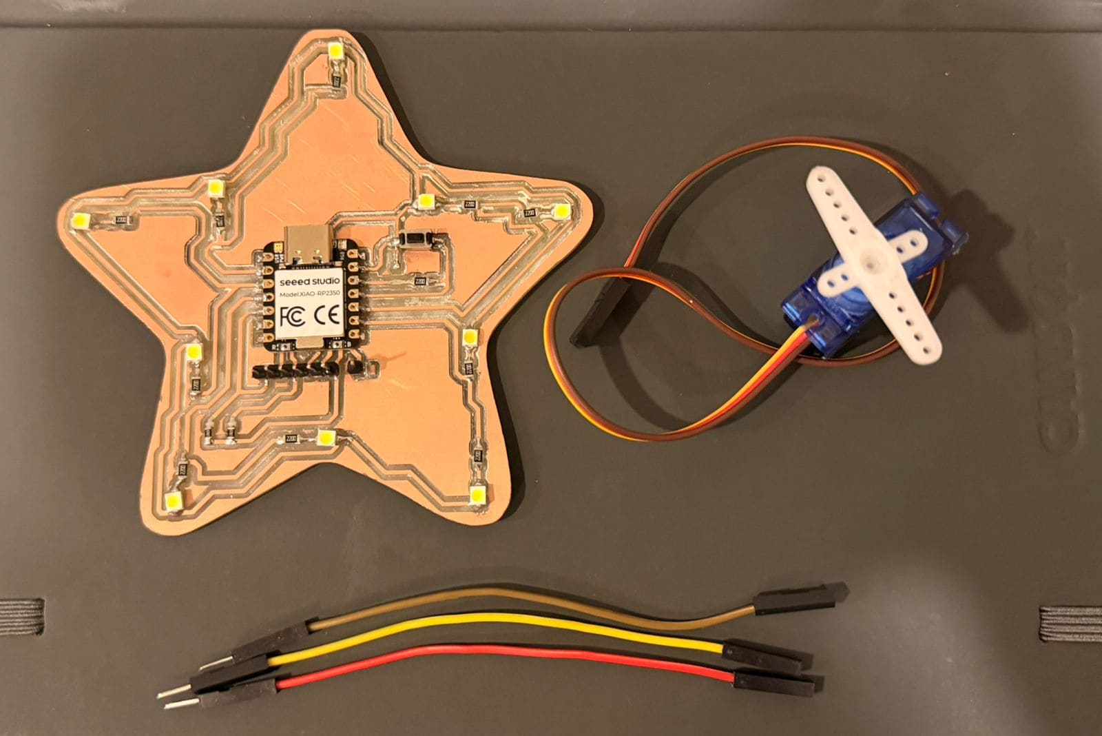
✦ Components
Although servomotors are controlled through a digital pin, they operate using a Pulse Width Modulation (PWM) to simulate an analog behavior; this allows a precise angle control (typically between 0º and 180º) instead of simple ON/OFF states.
◆ Check-List
1.PCB (Seeed XIAO RP2350)
2.Servomotor SG90
3.Dupont Cambles (3)
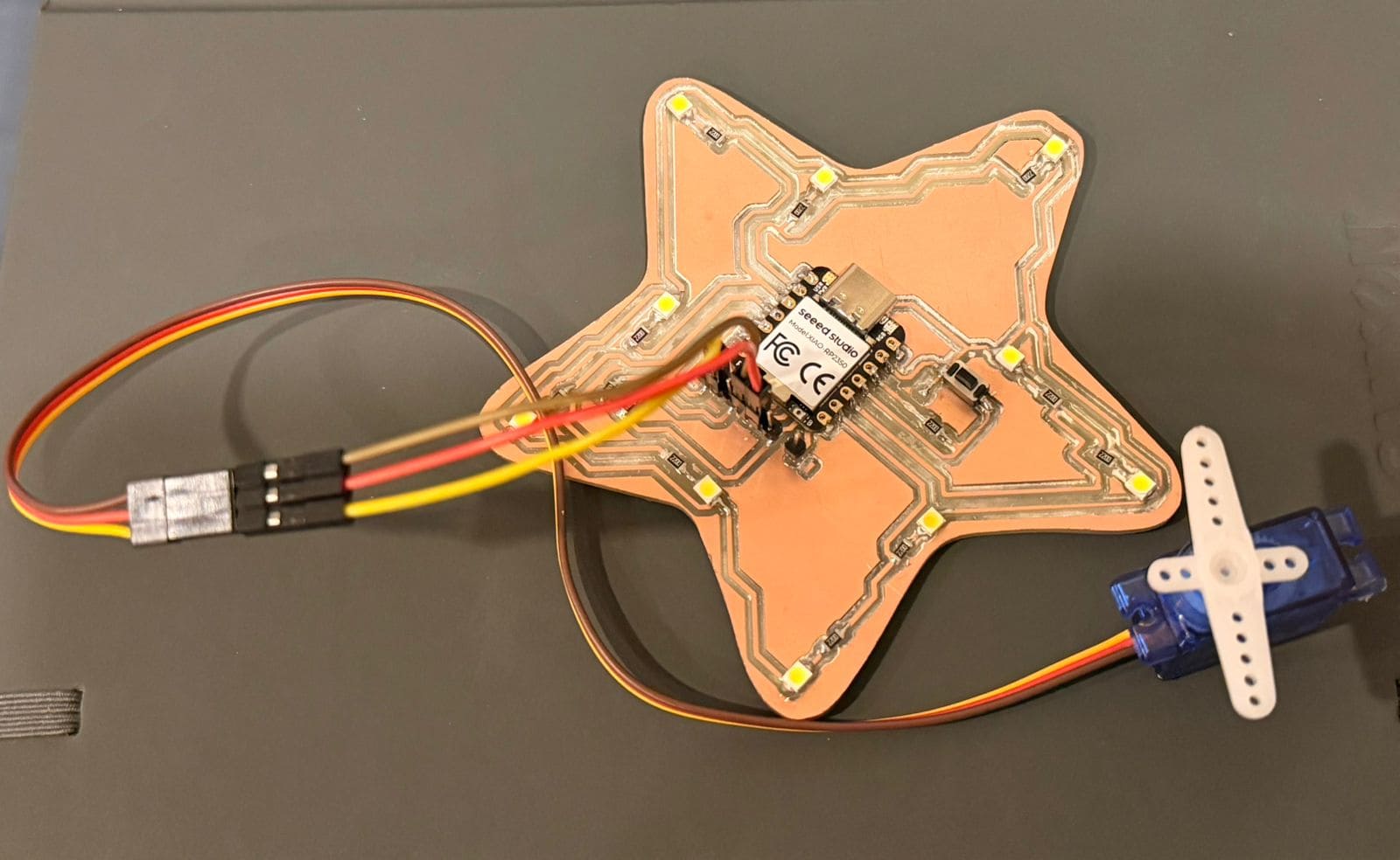
01. Servomotor Connection
Before starting, I connected the servo motor to the PWM, GND, and 5V pins of my board using jumper wires. Once that was done, I connected the PCB to the computer using cable C.
02. Test 1 (rotation from 0º to 180º)
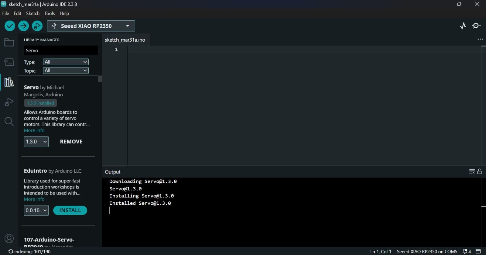
As a first test, I created a simple code that displays the servo motor's rotation angles: 0°, 90° and 180°. For this, I had to install the library. For this, I went to Tools → Board "Seeed XIAO RP2350" → Boards Manager and then search: Servo.h → Install.
✦ Code (C++)
Enter the following code in the ARDUINO IDE and click UPLOAD.
#include < Servo.h >
Servo myservo; // Create a servo object to control the motor
void setup() {
myservo.attach(D6); // Attach the servo motor to pin D6
}
void loop() {
myservo.write(0); // Move to 0 degrees
delay(1000); // Wait for 1 second
myservo.write(90); // Move to 90 degrees
delay(1000); // Wait for 1 second
myservo.write(180); // Move to 180 degrees
delay(1000); // Wait for 1 second
}
Command
Description
#include
Library that converts degrees into PWM signals for the motor.
.attach(D6)
Connects the servo object to the physical GPIO pin D6.
.write(angle)
Sets the shaft position to a specific degree (0°, 90°, or 180°).
delay(1000)
Provides the motor enough time to physically reach its position.Provides the motor enough time to physically reach its position.
GPIO Config
D10 is set as INPUT to read the sensor, while LED pins are OUTPUT.
03. Test 1 Results
The different steering angles of the servomotor can be seen, and we can also observe the signals and behaviors of the device by clicking on Serial Plotter and Serial Monitor in the upper right corner.
04. Test 2
For the second test, I decided to integrate additional behaviors into the servomotor, this time using other components on my PCB, such as a button and LED lights. The goal was to use the button as an ON/OFF control, while synchronizing the servo’s position and speed with the LED illumination, creating a coordinated and interactive response.
05. Gemini Code
Since I'm still new to device programming, I asked Gemini for help structuring the code. It's important to clarify the component connection pins on your PCB. Below is an example of the prompt:
◆ Prompt
"Please, help me structure an Arduino sketch for a XIAO RP2350 to control a servomotor (D6), a button (D10), and 5 LEDs (D1, D2, D3, D8, D9) so the device can follow 4 modes:
01. On (All LEDs ON, Servo 90°).
02. Sequential Chase (LEDs and Servo moving in sync).
03. Breathing (Servo sweeping 0-180° with progressive LED fading).
04. All OFF”.
#include < Servo.h >
Servo myservo;
int mode = 0; // Current operation mode
bool buttonPressed = false;
// Hardware Pin Definitions
const int BUTTON_PIN = D10;
const int SERVO_PIN = D6;
int leds[] = {D1, D2, D3, D8, D9}; // Array of the 5 LEDs pins
void setup() {
Serial.begin(115200); // Initialize Serial communication at 115200 baud
myservo.attach(SERVO_PIN); // Attach the servo to the defined pin
pinMode(BUTTON_PIN, INPUT_PULLUP); // Set button pin as input with internal pull-up
// Set all LED pins as outputs
for (int i = 0; i < 5; i++) {
pinMode(leds[i], OUTPUT);
}
myservo.write(0); // Initialize servo at 0 degrees
Serial.println("--- Greayshell's Star: System Rebooted ---");
}
void loop() {
// 1. BUTTON LOGIC (Mode Switching)
if (digitalRead(BUTTON_PIN) == LOW && !buttonPressed) {
delay(50); // Debounce delay
mode++; // Increment mode
if (mode > 3) mode = 0; // Reset to Mode 0 after Mode 3
buttonPressed = true;
Serial.print("Current Mode: "); Serial.println(mode);
// Clear all LEDs when switching modes
for(int i=0; i<5; i++) digitalWrite(leds[i], LOW);
}
// Reset button state when released
if (digitalRead(BUTTON_PIN) == HIGH) {
buttonPressed = false;
}
// 2. MODE EXECUTION (State Machine)
switch (mode) {
case 0: // STANDBY MODE (All OFF)
myservo.write(0);
for(int i=0; i<5; i++) digitalWrite(leds[i], LOW);
break;
case 1: // LAMP MODE (Fixed)
for(int i=0; i<5; i++) digitalWrite(leds[i], HIGH); // Turn all LEDs ON
myservo.write(90); // Set servo to 90 degrees
break;
case 2: // DYNAMIC MODE (Sequential Chase)
for(int i=0; i<5; i++) {
digitalWrite(leds[i], HIGH);
// Map the current LED to a servo angle between 20 and 160 degrees
myservo.write(map(i, 0, 4, 20, 160));
delay(150);
digitalWrite(leds[i], LOW);
if (digitalRead(BUTTON_PIN) == LOW) break; // Exit loop if button is pressed
}
break;
case 3: // BREATHING MODE (Organic Movement)
// Opening Sequence: Servo opens and LEDs light up progressively
for (int i = 0; i <= 180; i += 5) {
myservo.write(i);
// Turn on LEDs based on the servo angle ranges
if (i > 30) digitalWrite(leds[0], HIGH);
if (i > 60) digitalWrite(leds[1], HIGH);
if (i > 90) digitalWrite(leds[2], HIGH);
if (i > 120) digitalWrite(leds[3], HIGH);
if (i > 150) digitalWrite(leds[4], HIGH);
delay(30);
if (digitalRead(BUTTON_PIN) == LOW) return; // Fast interrupt for mode change
}
// Closing Sequence: Servo closes and LEDs turn off progressively
for (int i = 180; i >= 0; i -= 5) {
myservo.write(i);
if (i < 150) digitalWrite(leds[4], LOW);
if (i < 120) digitalWrite(leds[3], LOW);
if (i < 90) digitalWrite(leds[2], LOW);
if (i < 60) digitalWrite(leds[1], LOW);
if (i < 30) digitalWrite(leds[0], LOW);
delay(30);
if (digitalRead(BUTTON_PIN) == LOW) return;
}
break;
}
}
Command
Description
State Machine
Organizes 4 modes (Standby, Lamp, Dynamic, Breathing) for clean execution.
map(i, 0, 4, 20, 160)
Converts the LED position into a servo angle between 20° and 160°.
Interrupts
Allows the button to break animations instantly for a faster response.
pinMode(BUTTON_PIN, INPUT_PULLUP
Sets the button as an input using the internal pull-up resistor.
Serial.println()
Displays a startup message in the Serial Monitor.
if (digitalRead(BUTTON_PIN) == LOW && !buttonPressed)
Detects when the button is pressed.
for (int i = 180; i >= 0; i -= 5)
Moves the servo back to 0° while LEDs progressively turn off.
switch (mode)
Controls different behaviors depending on the selected mode.
for (int i = 180; i >= 0; i -= 5)
Moves the servo back to 0° while LEDs progressively turn off.
✦ Uploading the Code in Arduino IDE.
To read the data from the sensor, the program was uploades to the microcontroller using Arduino IDE. For more information go to my Week 8.
✦ Test 2 Results
The results demonstrate how the servomotor and LED outputs follow the programmed instructions, while dynamically responding to the mode changes controlled by the button.
✦ Reflection
Working with a servomotor expanded the understanding of output devices by introducing controlled motion instead of simple responses. This made it clear how outputs can create more dynamic and interactive behaviors.
✦ Download Here!
In this section, you can find the downloadable source files developed during this week.