During this week, I focused on understanding how microcontrollers perceive the physical surroundings through input devices.
Also, the main objective of the assignment was to integrate a sensor to the the PCB I designed in Week 8 and read its
data. For this, I will be using a PIR (Passive Infrared) motion sensor, an electronic device that detects movement based on changes in infrared radiation.
Also, I will be consulting our Group Assignment.
◆ What is an Input Device?
An input device is a component that allows a microcontroller to receive information from its surroundings. It converts physical phenomena into electrical signals that can be read and processed. Besides, depending on the sensor’s architecture, this communication occurs through two types of signals.
Signal
Description
Analog
Continuous values that vary over time, such as temperature or light intensity.
Digital
Discrete values represented as HIGH or LOW, such as a button press or motion detection.
I2C Communication
Digital communication protocol that allows multiple devices to send data using two lines (SDA AND SCL).
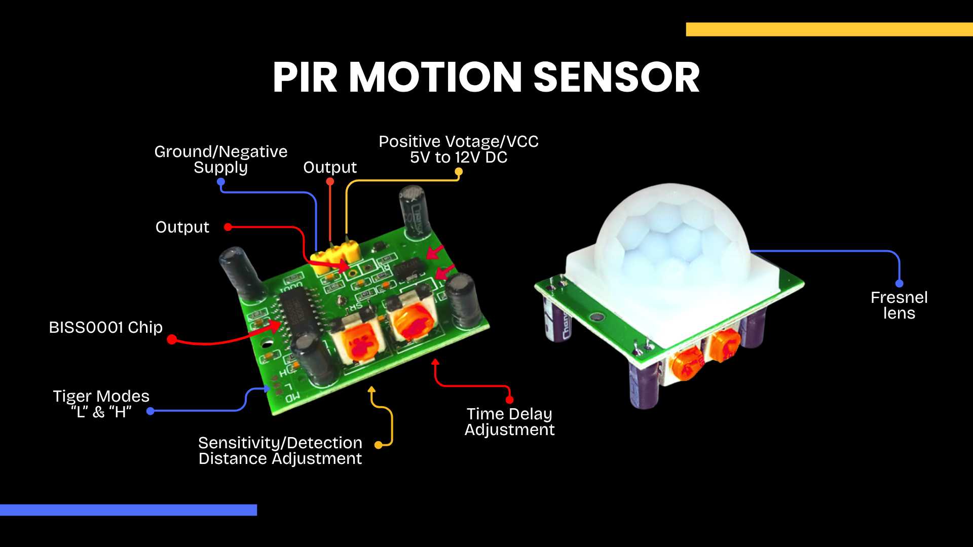
✦ PIR Motion Sensor
The PIR (Passive Infrared) sensor detects motion by measuring changes in infrared radiation emitted by objects, such as the human body. When a person crosses its field of view, the sensor registers this thermal variation and outputs a digital signal.
The PIR sensor communicates via a digital signal, operating on a binary state. When the sensor detects movement through thermal variations, it triggers a HIGH output. Conversely, when the environment remains static, the output defaults to a LOW state.
◆ Components
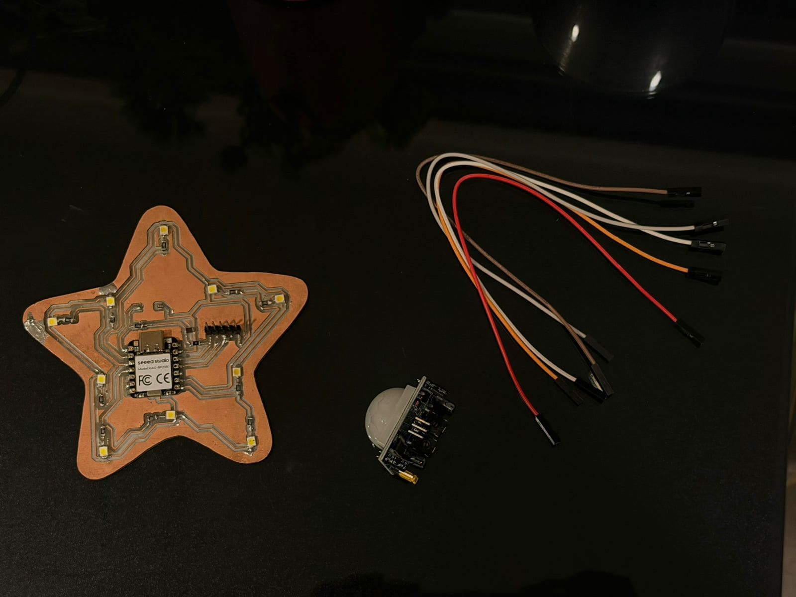
✦ What I will be using?
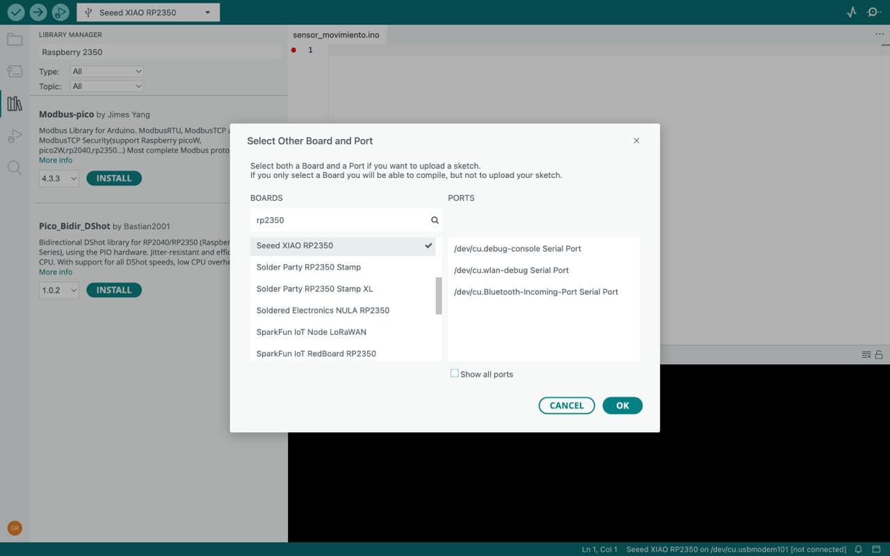
1.Seeed XIAO RP2035
2.PIR Motion Sensor
3.Jumper wires
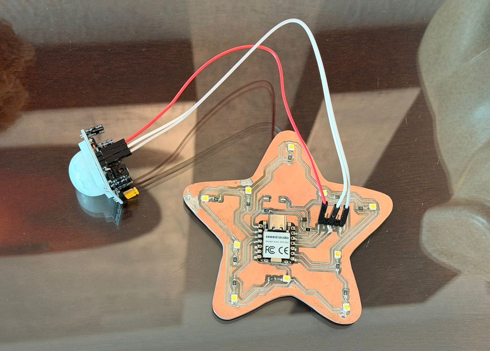
◆ Circuit Connections
The PIR sensor typically has three pins:
1. VCC → 3.3V
2. GND → GND
3. OUT → Digital pin
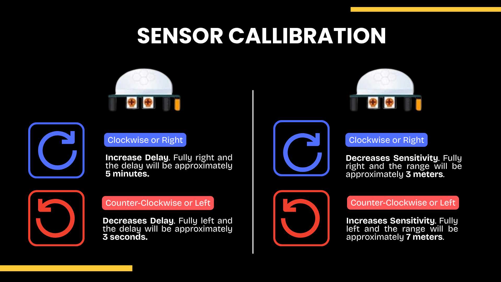
✦ Sensor Callibration
Adjustment controls of the PIR motion sensor. The module includes two potentiometers: one for time delay and another for sensitivity. Rotating clockwise increases the delay time (up to 5 minutes) and decreases sensitivity (down to 3 meters), while rotating counterclockwise reduces the delay (down to 3 seconds) and increases the sensitivity (up to 7 meters).
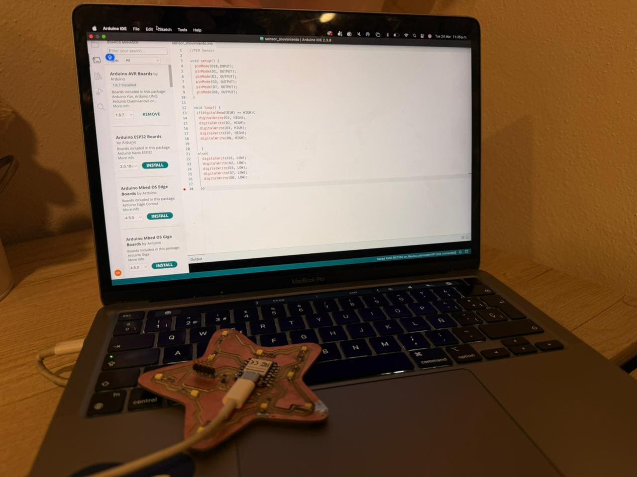
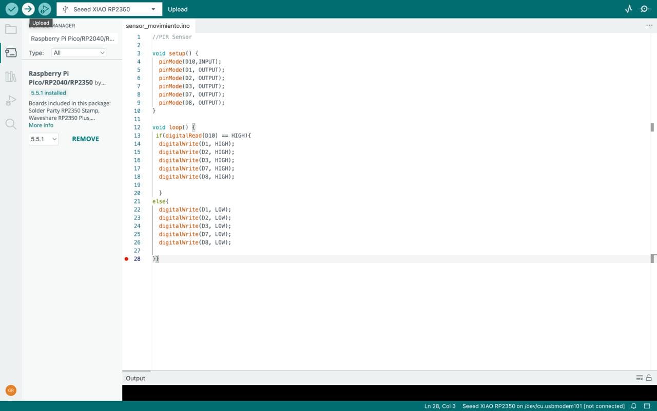
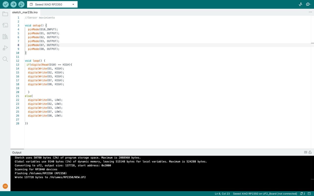
✦ Programming (C++)
The following code is programmed so that when the sensor detects nearby movement, the LED lights on the PCB will illuminate, remaining on for a few seconds, and then turn off when no nearby presence is detected.
Throughout this week, I encountered some difficulties as I had to delve deeper into the world of electronics. Therefore, I can say there was a lot of trial and error when programming the Arduino code, as it was my first time using it. However, I was able to achieve the assignment goal, and I'm surprised by what I was able to accomplish during the week of inputs.
✦ Download Here!
In this section, you can find the downloadable source files developed during this week.