9. Input Devices
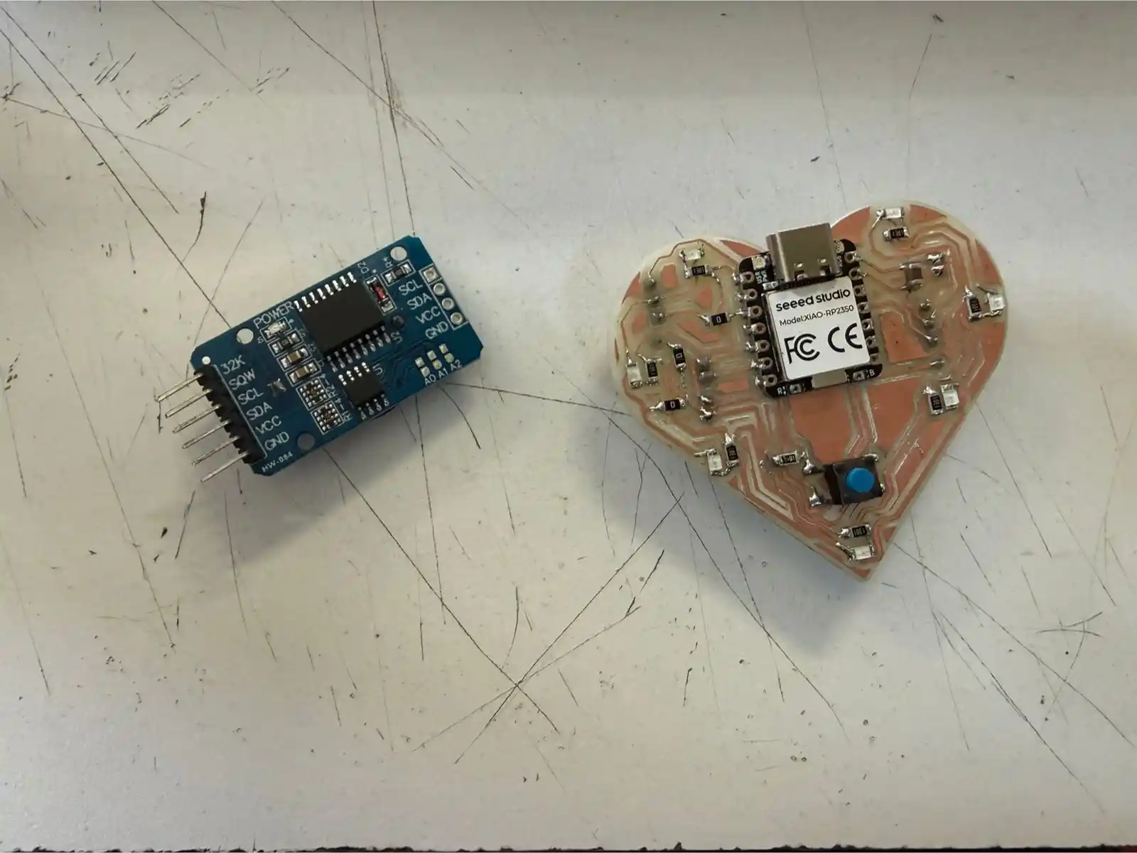
The objective this week was to integrate two distinct data input methods using the Seeed Studio XIAO RP2350; the board I used was the one I made in week 8. This week's assignment consisted of capturing distance through an analog sensor and obtaining the current time via a Real-Time Clock (RTC) module using digital communication.
For more information on how input devices function, you can visit our GROUP PAGE.
Analog sensors
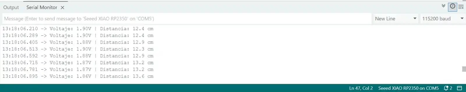
Analog sensors (such as potentiometers, LDR light sensors, or temperature sensors) output a continuous voltage signal. The XIAO RP2350 features a high-resolution Analog-to-Digital Converter (ADC).
If the sensor outputs 1.65V (which is exactly half of the 3.3V reference), the ADC references its internal "ruler" to assign a digital value. In this case, with a 12-bit resolution, it would correspond to level 2048.
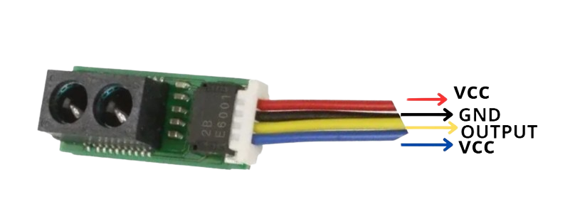
The specific sensor I am using is the Sharp GP2Y0E02A (you can find its datasheet here). It has an effective measuring range of 4 to 50 cm.
RTC Module (Real Time Clock) via I2C
Unlike the main processor, which loses track of time if it loses power, the RTC module maintains the exact time thanks to an external battery. To communicate it with the XIAO RP2350, I used the I2C protocol.
I used the dedicated pins on the XIAO (SDA and SCL). The microcontroller requests information from a specific address (e.g., 0x68), and the RTC responds by sending packets of bytes representing seconds, minutes, and hours.
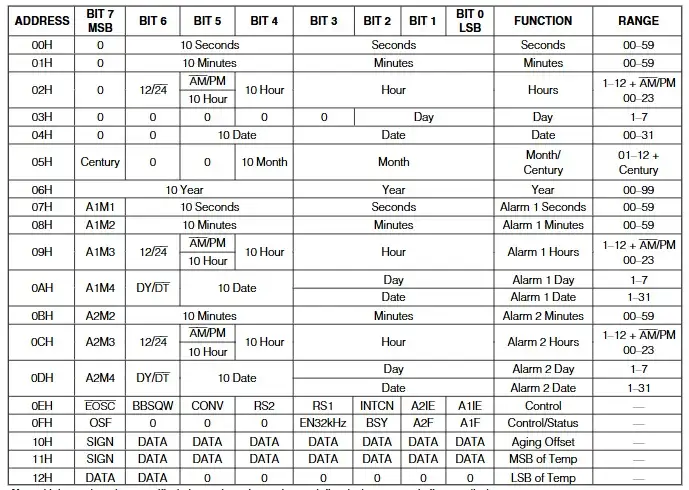
RTCs typically deliver data in Binary Coded Decimal (BCD) format, which requires a small mathematical conversion in the code to display the numbers in standard decimal format.
The image below shows the registers through which the RTC operates; you can find this map in the datasheet.
1. Programming the XIAO RP2350
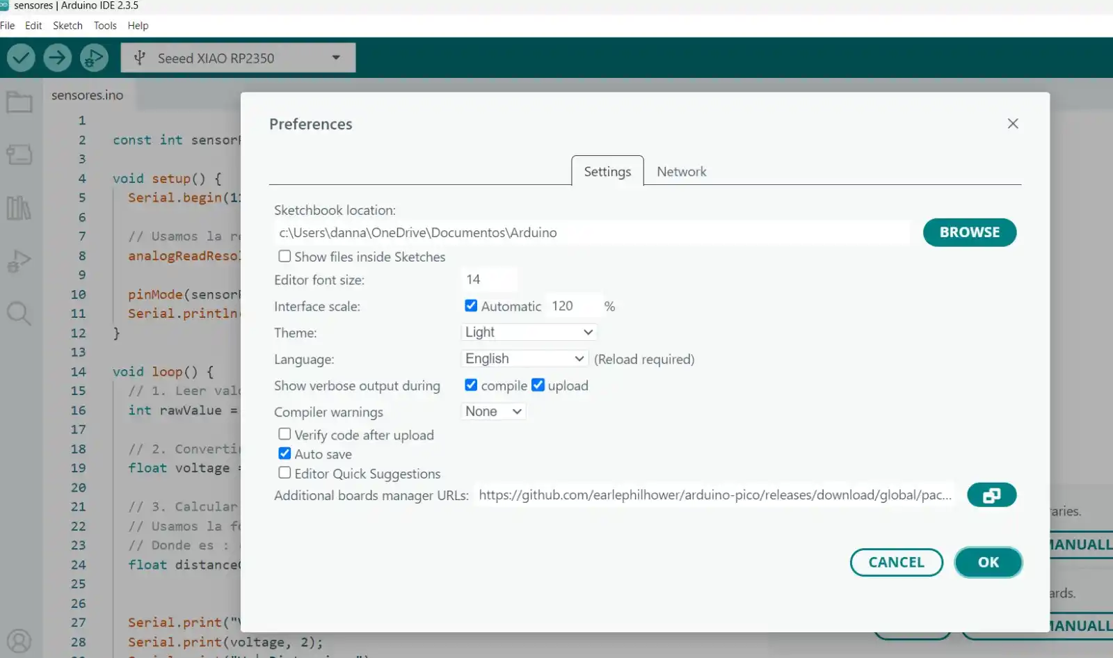
To program the XIAO RP2350 in the Arduino IDE, I followed these steps:
- Go to File > Preferences.
- In the Additional Boards Manager URLs section, paste the following link:
https://github.com/earlephilhower/arduino-pico/releases/download/global/package_rp2040_index.json
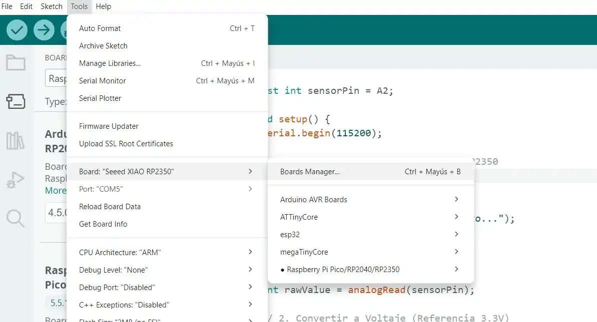
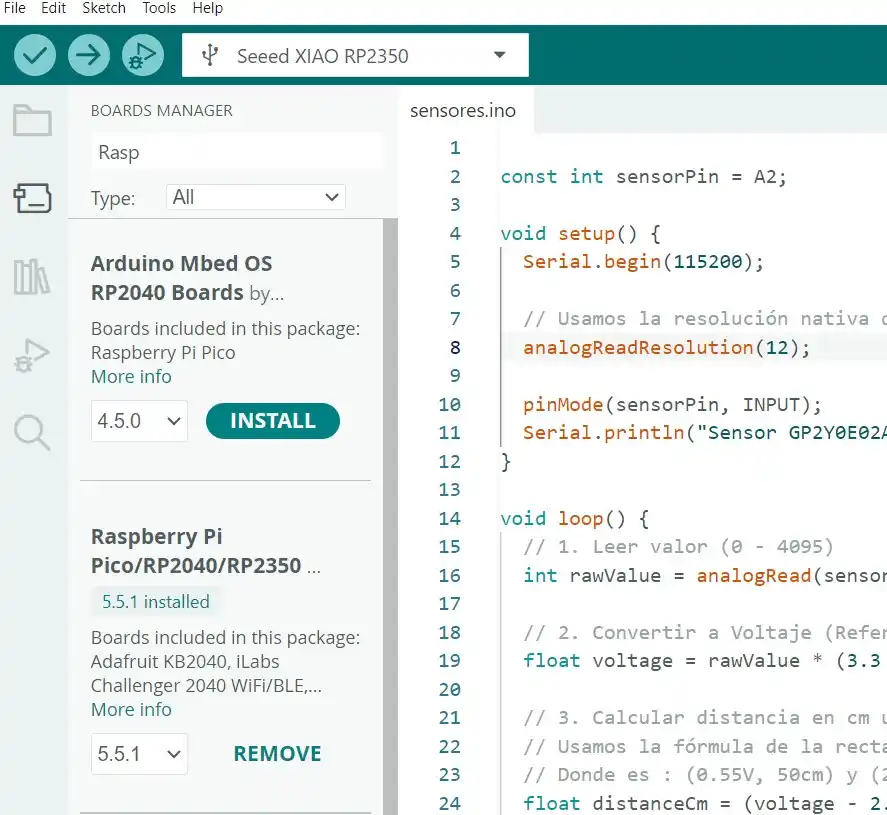
- Go to Tools > Board > Boards Manager...
- Search for Raspberry Pi Pico/RP2040/RP2350 and install it.
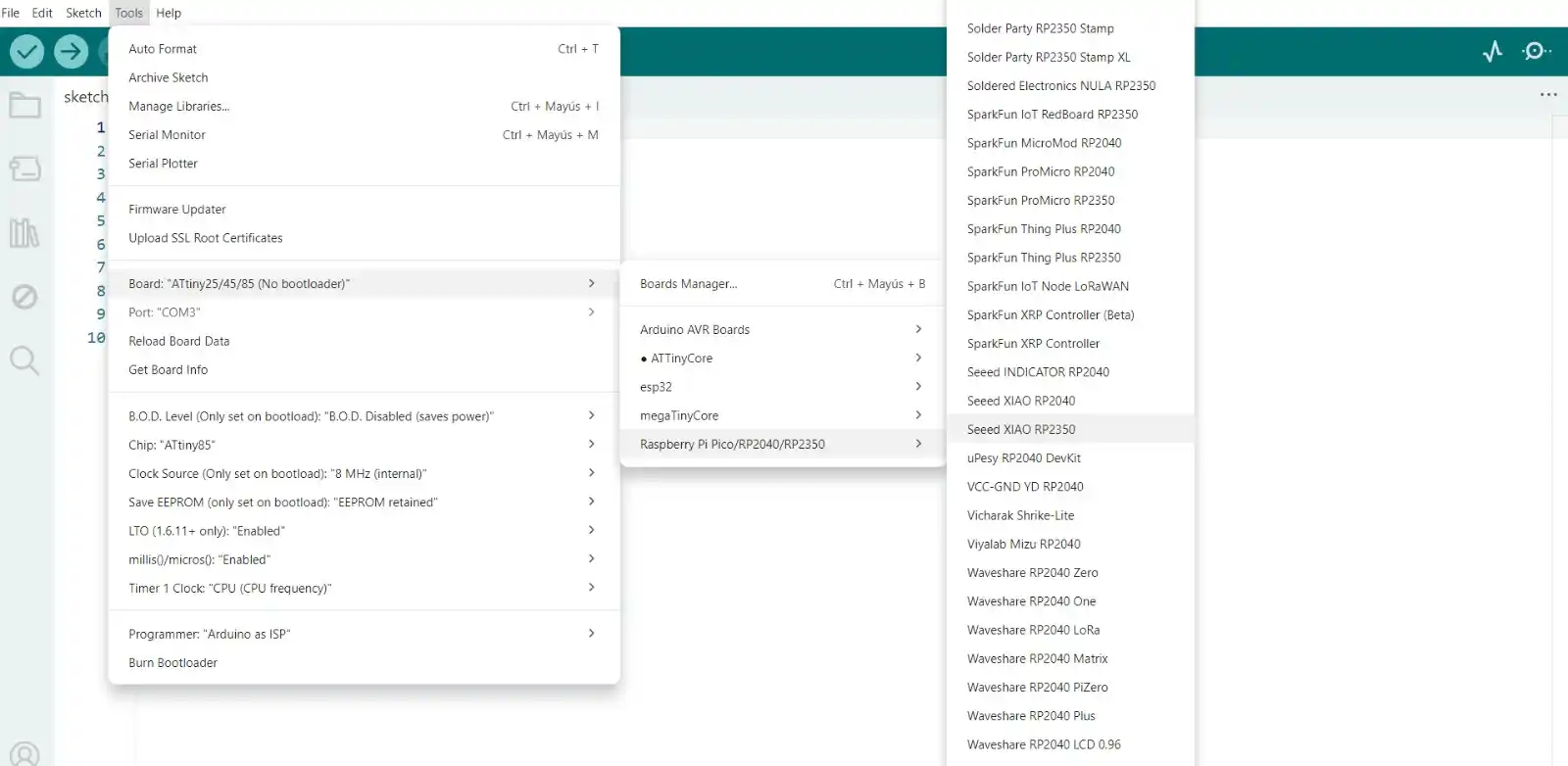
- Once installed, select your specific hardware:
- Board: Tools > Board > Raspberry Pi RP2350 Boards > Seeed XIAO RP2350.
- Connect the XIAO to your computer via USB-C.
- Press and hold the BOOT button.
- Press and release the RESET button.
- Release the BOOT button.
2. INPUTS
I2C SENSOR (RTC)
CODE
#include <stdio.h>
#include "hardware/i2c.h"
#include "pico/binary_info.h"

// Hardware Configuration
#define I2C_PORT i2c1
#define PIN_SDA 6
#define PIN_SCL 7
#define DS3231_ADDR 0x68

// BCD conversion functions
uint8_t bcdToDec(uint8_t val) { return ((val / 16 * 10) + (val % 16)); }

void setup() {
  Serial.begin(115200);

// Wait for serial monitor
  while (!Serial && millis() < 3000);

// Initialize I2C
  i2c_init(I2C_PORT, 100 * 1000);
  gpio_set_function(PIN_SDA, GPIO_FUNC_I2C);
  gpio_set_function(PIN_SCL, GPIO_FUNC_I2C);

// Active pull-ups
  gpio_pull_up(PIN_SDA);
  gpio_pull_up(PIN_SCL);

  Serial.println("--- MODO LECTURA: Reloj DS3231 Activo ---");
}

void loop() {
  uint8_t reg = 0x00; // Start recording (seconds)
  uint8_t data[3];    // Buffer for [0]=sec, [1]=min, [2]=hours


  i2c_write_blocking(I2C_PORT, DS3231_ADDR, ®, 1, true);


  int bytes_read = i2c_read_blocking(I2C_PORT, DS3231_ADDR, data, 3, false);

  if (bytes_read < 0) {
    Serial.println("Error: No se detecta el reloj. Revisa cables.");
  } else {
// Convert data from BCD to Decimal
    uint8_t segundos = bcdToDec(data[0]);
    uint8_t minutos  = bcdToDec(data[1]);
    uint8_t horas    = bcdToDec(data[2] & 0x3F); // Mask for 24h format


    Serial.print("\nHora actual: ");

    if (horas < 10) Serial.print('0');
    Serial.print(horas);
    Serial.print(':');

    if (minutos < 10) Serial.print('0');
    Serial.print(minutos);
    Serial.print(':');

    if (segundos < 10) Serial.print('0');
    Serial.print(segundos);


    Serial.print("\t");
  }

  delay(1000);
}
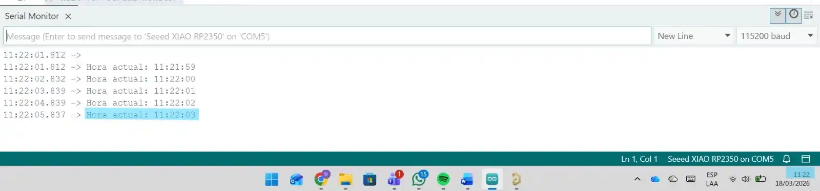
RESULT