Systems
Project Goals
This project involves multiple systems that can be added or discarded, depending on the time available for me to complete my final project. This systems are listed as follow:
| Priority | Included Systems |
|---|---|
| BASE | Octopus shaped casing for a Raspberry Pi 5 with an LLM model, with user voice input and Text to Speech output. |
| 1 | Added a person recognition module (Xiao Sense) to track the user position and adjust a rotating base as needed. |
| 2 | Added a rotating base that moves to the general direction of the user voice. |
| 3 | (SCRAPPED) Added servo motors on the base of the articulated tentacles to enable the “tentacle movement” play feature. |
| 4 | Added a capacitive sensor in the head of the robot to enable the “petting” play feature. |
This goals work as a pyramid, where the base of the pyramid is the BASE tier and the top is the “3” tier. If time becomes a problem during the development of the project, the included systems will be removed from top to bottom.
Note: Not including one of these goals into the final project is not an indication of failure. The objective of this goals table is to have a hierarchy of implementation of all the proposed systems of the final project, in case time becomes an issue and some parts of the project need to be left behind.
April 27
Task Manager
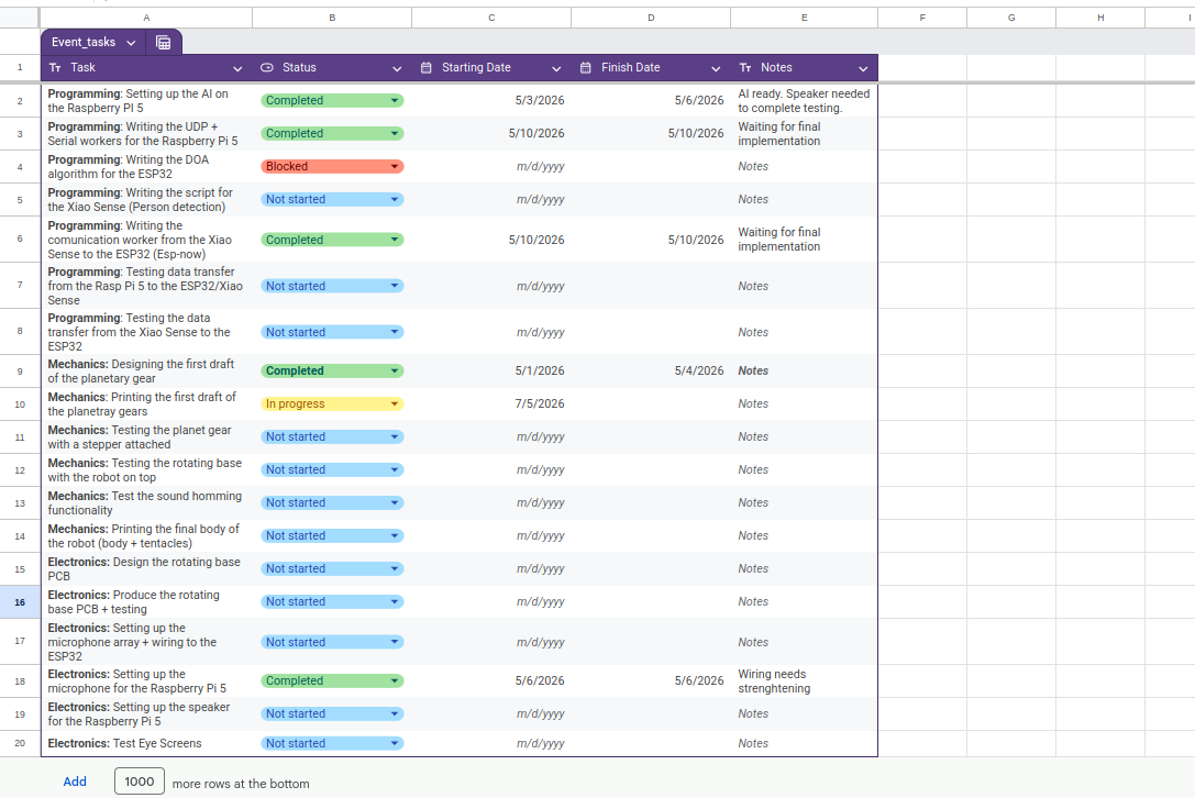
For this project I created a google sheets document to track my pending tasks. This tasks manager will be including time stamps of the initialization and ending of a task. In the near future, the ending of each task will be scheduled.
User Diagram
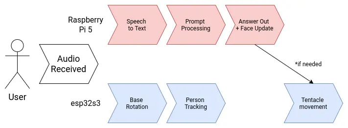
Note: As of May 3th, the servo movement functionality is now scrapped
Brain Diagram
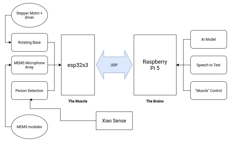
My project involves two main brain requirements. The first one being the LLM processing aspect. This part will take care of "hosting the AI", plus anything involved with its functioning, like the speech to text and text to speech services. The second one being the peripherals control. This being any input and output devices included in the project, like the microphone array and the tentacle movement. Having a single micro-controller or single board computer to do all of this is not optimal. In the spirit of "dividing and conquering", I decided to separate both systems into a "muscle and brain" configuration.
The "brain" of the robot will be a Raspberry Pi 5. Raspberry Pi 5 are small and powerful single board computers, already used for AI applications like hosting local LLMs. The Raspberry Pi 5 by itself can perfectly run all of my AI related services by itself. The "muscle" of the robot will be an esp32s3. This is a fast and versatile micro-controller powerful enough to handle any input and output device we attach to it. Both the muscle and brain need to be connected to one another to coordinate. Specially for sending activation signals from the brain to the muscle. For this, an UART connection will suffice. If a more complex communication necessity presents during the development process of the robot, both offer WiFi connectivity, opening the possibility for an HTTP connection as well.
April 21
Note: A small correction to the diagram was made on *April 27*. The Raspberry Pi 5 will now have a dedicated microphone for itself. For more information on this change, please refer to the MEMS microphone array section of this page.
April 29
Electronics
Power Supply
April 17
There are multiple voltage requirements for the different systems present in our robot:
- The stepper-motor controller will need a 12v supply.
- The Raspberry Pi 5, esp32s3 and Xiao Sense will need a 5v supply.
- Servo motors work best at 6v.(SCRAPPED)
- The MEMS microphone modules will need a 3.3v supply.
Working with multiple voltage requirements is usually not a big deal. Many electronics, like laptops for example, have a base voltage input (usually the larges most used voltage) and then it´s transformed accordingly. Using a buck converter for the 5V and 6V line, our voltage problems will be solved:
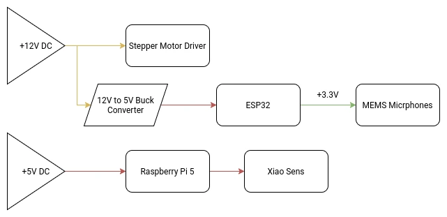
Our main +12V DC power source will be an external 12V 5A power supply. 5A should be enough for our consumption requirements, although bumping it up to 10A might be necessary. I’m not an expert and can’t really do the needed calculations to get my max amperage value. If I get to that value (with help of my instructors), and it’s greater than 5A, I will be changing the power supply.
At the time of updating this, the one concern I have is with my slip ring. The slip ring I ordered comes with pretty thin cables. This is why I ordered one with 8 cables, with the intention of using multiple cables for a single power line in order to protect those cables. For the 4 lines I will be needing (Ground and 3 +12V lines), it leaves me with 2 cables per line, that should be enough to sustain the power going through them. If two cables per line is not enough, there is a 12 cable option I could get.
(SCRAPPED) The Servo Motor Array
Each tentacle of the robot will have a servo motor attached to its base. This servo motor will give the tentacle an upwards and downwards movement. This simple movement configuration is enough to give the robot its desired functionality.
Out of the 6 proposed tentacles for the final model there are 4 types of motors.
- Lead tentacle x1
- Type A tentacles x2
- Type B tentacles x3
The Lead tentacle will be used as the “dominant hand” of the robot, which will be important for some of the play features planned for it. The rest of the motors will be divided into type A and B motors. Differentiating between motors will also help us with the play functions.
The tentacle servo motor system is only meant to be used for play features an will serve no other function for the rest of the system. With that being said, this system will be classified as low-priority, meaning that it will be one of the last functions added and subject to being removed if time constrains demand it.
As of the time of writing this paragraph, the servo motor array was scrapped from the project. The main reason for this decision was the difficulty to power all of the motors. It is important to remember that the servo motors would have been installed inside the robot’s casing. Powering each servo motor would require a complete re design of the power system. The Raspberry Pi 5 by itself cannot power this system by itself. Outside power would be required, adding an extra power supply to the mix. As it is, the robot requires two power outlets: the 12v supply and the Raspberry Pi 5 dedicated charger.
Plus, Servo motors are known for causing noise to other signals. Our main communication protocols are wireless (ESP-Now and UDP), meaning that they are really susceptible to this kind of noise. In an application where data precision and real time transfer is required, even the slight interference can cause problems.
For future versions of this project, the servo motor array will be considered, as it would really help our robot come to life. For the time being, the servo motor array system cannot be considered.
May 3th
MEMS Microphone Array
April 27
The original idea was to follow the common practice of using a microphone array for speech input into my robot, like how te “Alexas” work. For this, i decided to go with MEMS type microphones, for its low cost, low power, small size and audio quality capabilities. I bought 5 INMP441 microphone modules for this application. The idea is that these microphones will serve as the sound detection and speech receiver system of my robot like so:
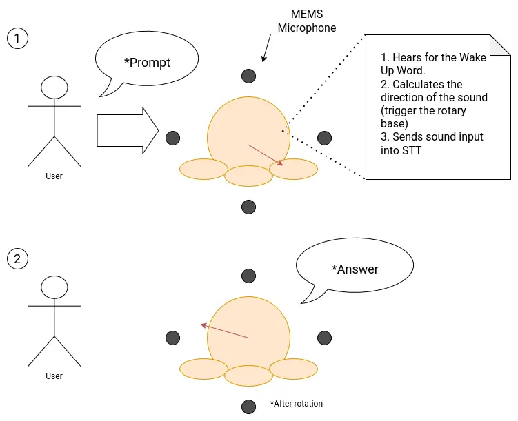
For this system to properly function, I need a way of converting the microphone array connected to the esp32s3 into a sound input that the Raspberry pi 5 can read from. At the time of writing this, it is the Interface week, and I tried to tackle this problem whilst integrating it into my week’s work. The proposed system turned out to be way complex than I originally had envisioned. The hearth of the problem relied on how to solve the bridge between the microphone array + esp32s3 and the Rasp Pi.
MEMS microphones work with the I2S protocol: a protocol designed specifically for digital sound transmitting. As seen on my input devices week the INMP441 module works perfectly fine at receiving sound and outputting it into raw data. The graphs generated for that week’s work showed just how capable this microphones are at receiving any kind of sound. The problem comes with translating these I2S data into a usable form for my Speech to Text (see more on the Programming Section).
I did some research and asked instructors for advice and came up with two possible solutions for this problem:
- Convert the esp32 + microphone array into an actual USB microphone my Rasp Pi could detect on its OS and capture my voice from.
- Convert the raw I2S data into a .wav file and sending it into my Rasp Pi.
The first solution is pretty straight forward. Converting the esp32 into a microphone would allow me a “plug & play” experience, by using it as I would a regular microphone. The second solution came after seeing this Youtube video by the Techiesms channel. In this video, the author was able to send a .wav to an Speech to Text api in order to receive the translated text, all inside a single esp32 Wroom. His approach involved using an SD card to save the generated .wav file from the microphone input, sending this file to an api via HTTPS and receiving the transcription.
The Problems With These Solution
Both of these solutions sound great on paper, but once diving deep into what would take for each of them to work revealed a discouraging outlook.
Starting with the first solution, converting the esp32 into a usable microphone to “plug & play” to the Rasp Pi is not as straight forward as I originally envisioned it. Turns out that a lot of things are required for this microphone + micro-controller system. It would not only require a combination of libraries that I don’t know how to use or have little documentation and user examples (similarly to what originally happened to me in my input device week). There would also be a need of working with the Rasp Pi audio drivers in order to properly use the microphone array like a real microphone. Plus, having the esp32 work as a dedicated microphone would probably hinder my sound direction functionality, as doing this requires dedicated calculations and integrations with other parts of the system. Adding an extra micro-controller, like an RP2350, would not solve the issue either, it would only complicate things by adding another unnecessary layer of complexity to my already developed system.
The second solution seemed promising at first. Then I realized that I don’t have an SD module for my esp32s3. This means that saving a whole .wav file, even of just a couple of seconds, would be imposible for my micro-controller. With out the SD option, I would have to implement a way of dividing the incoming audio into segments, send each segment individually to the Rasp Pi and deleting it to create more space for the following one, and then re-construct the file in the Rasp Pi. Needless to say, this solution brings a whole plethora of problems by itself. The “divide & conquer” approach does not work in an application where synchronization is key. Dividing the incoming voice into chunks and sending them individually would cause lag in our system, making our prompt processing, sound direction calculation and rotating base movement to not work properly.
The Proposed Solution
As of the time of writing this, the third solution I could come up with seems to be the easiest to implement, and the one that solves all of my issues: Adding an extra microphone (not MEMS or MEMS, more on that later) to the Rasp Pi. This new microphone will be exclusively used receiving the voice, in order to detect the wake up word and trigger the Speech to Text. The rest of my functionalities, those being the sound direction calculation, can still be done using my original INMP441 microphone array. The esp32 would only require the already possible raw inputs of the INMP441 microphones to detect where the sound is coming from. This solution solves the need of implementing a way of connecting the microphones + esp32, essentially removing that “bridge” that was the hearth of the issue. With this, our sound system would now look like this:
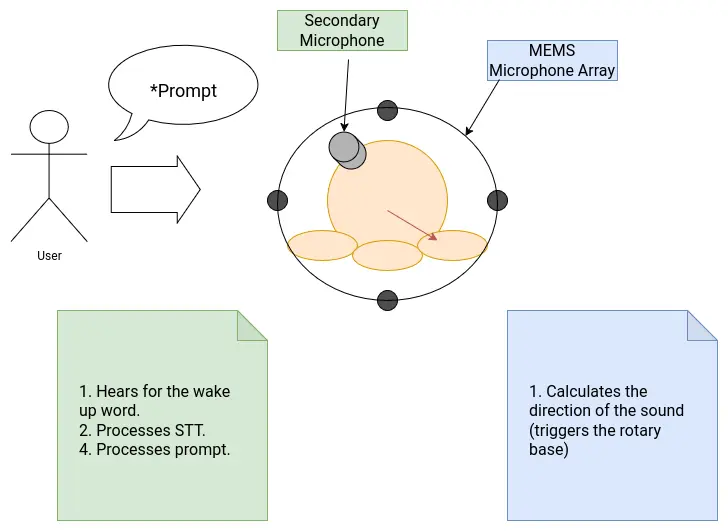
The only downside of this solution is the inclusion of another microphone into the system. Luckily for me, it seems like the Rasp Pi has an I2S interface on its pins. In theory, connecting an INMP441 directly into this I2S interface would allow me to use it as a microphone without much configuration needed, other than fine tuning the I2S parameters. The INMP441 is omnidirectional, so strategically placing it into, say, the head of robot, should give it enough range to detect voice in a 360 degree way.
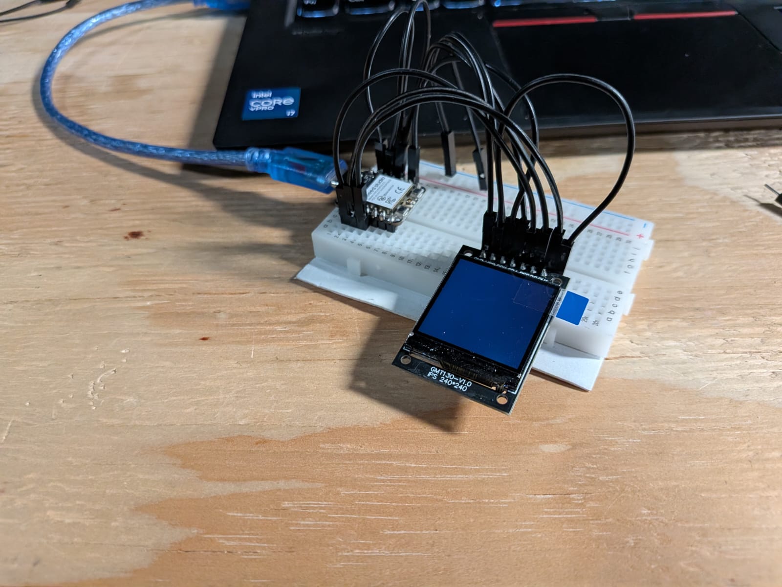
Eye Screens
For the eyes of my robot I was going to use two mini OLED screens. These OLED screens would showcase a simple video of blinking eyes. The original plan was to link the expressions shown on the screens with the AI response, emoting in reaction of the emotion showed by the AI at the moment. In the end, doing this seemed a little bit hard and “overkill”, as in reality our robot only needs two states: an idle state and a “prompt received” state, which was planed to be a “closed happy eyes” expression. With that, I only needed to design a video and an image: a blinking image, and the happy eyes. And in the python script, we could change the expression at any given time, those being the waiting for a wake word and starting to answer the prompt.
The python script would require us to use a custom library for the screen. The OLED screens I had available on the Lab used a st7789 drive. This drive can be controlled by the “st7789py” python library. We need a python library as the screen controlling needs to happen inside our main python screen. The “st7789py” library can be found with the pip package manager, and can be installed by running pip install st7789py in our terminal. Alternatively, you can download the original script from its GitHub repo and place it in your working folder.
The OLED screen is connected via GPIO pins, powered by 5v. The Raspberry Pi 5 has two 5v pins, enough for both screens. I connected every pin to an available GPIO pin. Then, using AI, I generated a testing code for the screen, including shape drawing, text displaying and image displaying. I ran the scripts, but the screen did not show any image.
AI assisted debugging resulted in nothing useful. Only researching had the same results, as there is almost no documentation on this library. There are a few forums related, but most of them only focused on the “connecting” part of the OLED screen, not debugging the st7789py library itself. The only forum with some useful information said that the st7789py library mixes up the GPIO pin number for two pins, and that I should “change it”, without specifying what and where. Still, I physically changed the wiring of my OLED screen to match this proposed “fix”, but it didn’t work.
In the end I tried finding other libraries or alternatives that didn’t used the st7789py library, but I couldn’t find any. There is simply no information available out there on how to run an OLED screen with the st7789 driver with micropython. There is, however, plenty of information on how to run them with Arduino. The problem with this is that running it with Arduino is not possible without an extra micro-controller hooked to them. Using an extra Xiao micro-controller seemed to be an option, but these micro-controllers only have a single 5v pin. Hooking both screens to this pin would most likely cause an over consumption, possibly harming the micro-controller. Plus, this extra micro-controller would need a way to communicate with the Raspberry Pi, complicating further its implementation.
However, there was a simpler solution. Using an I2C screen instead of our current model will solve every issue. For starters, I2C screens only need 4 pins, my current screen needed 7 pins. Plus, sending data from a micropython screen through I2C is way easier, not needing an undocumented library like st7789py (no hate to the original creator). I2C screens might not be best to showcase images, but using ASCII art we can accomplish a similar and more stylish eye solution. Here’s the big problem. There are currently no stores in my city that sell these screens. The only option is importing from Ali-Express. This means that the screens, even if I bought them right now, wouldn’t arrive on time. Final project presentations start on June 8th, and the fastest these screens could arrive is on June 6th, leaving me two days to test and implement into my project.
As time is running out, and the window of opportunity to implement this screens is to small, without mentioning the evident possibility of them not working as expected, means that I needed to take a difficult decision: I decided to scrap the eye screens for this project. I just cannot take the risk of not getting the screens on time, or them not working, leaving me a small time to come with a solution. This is why I decided that the face of my robot will be static, most likely in the form of a vinyl cutout. This solution removes that “livelihood” part of the robot, but its the smart decision to make at the moment.
It is starting to bug me the amount of ideas proposed that I had to scrap. In the end, this is not a symptom of my “reduced skills”, it shows how much I’ve learnt and grown as an engineer and maker during this FAB Academy 2026. Having the maturity to distinguish if something is not possible to implement in a project, taking into consideration time, skill and resources. It is a shame, because I have the solution to the problem right there, but it will have to wait for a further version of this robot.
May 19th
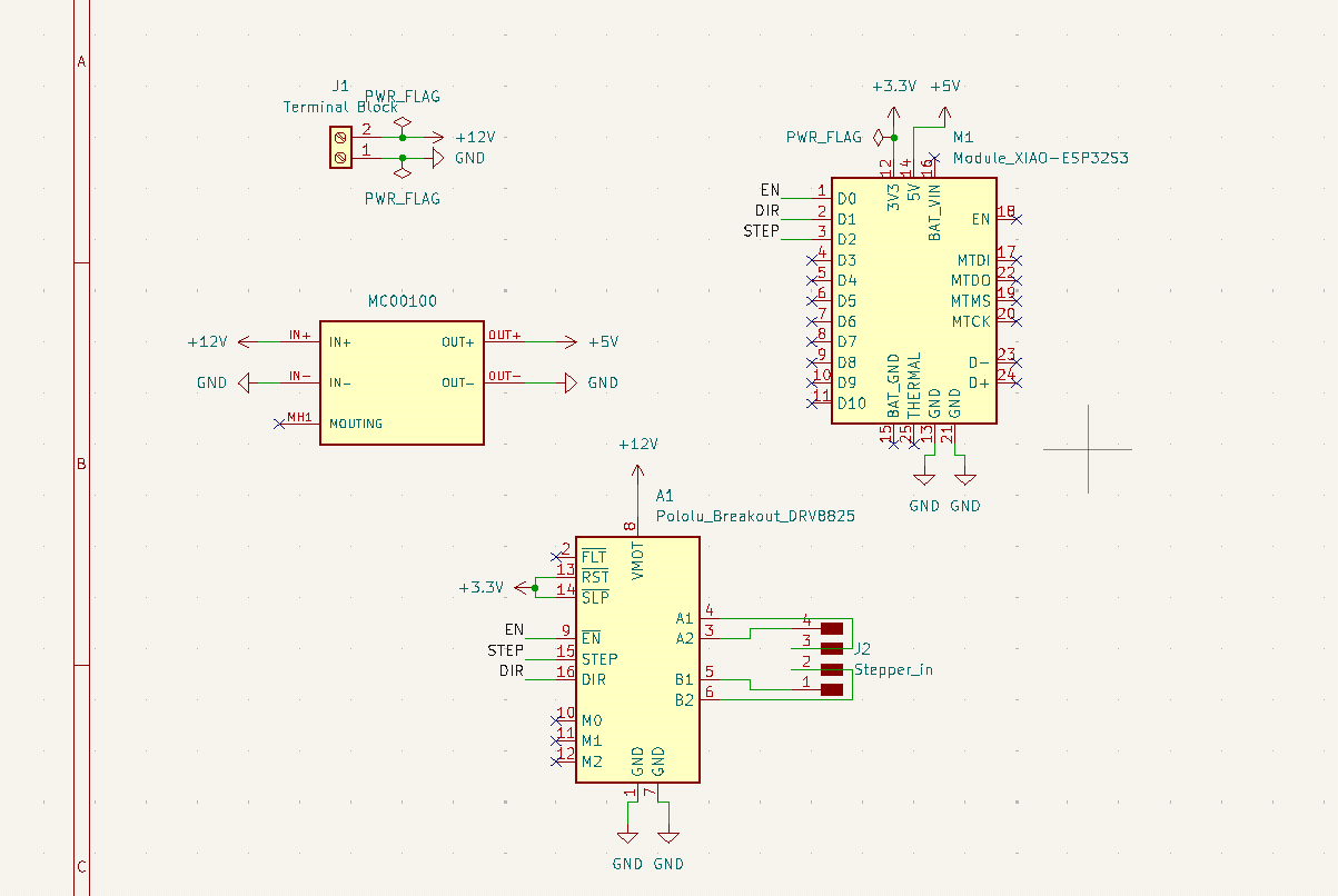
PCB Design
The original plan consisted on having an internal PCB on the base of the robot. This PCB would have included:
- The micro-controller (ESP32).
- The drv8825 driver for the stepper motor.
- A 12v to 5v buck converter, for powering the ESP32.
- Connections for the Stepper motor wires.
- A DC input connection, most likely a screw terminal.
However, as of the time of writing this entry, the plan has changed. Now, the person tracking has a bigger priority over the sound detection system with the mems microphone array. For more information on why this decision was taken, pelase refer to the programming - DOA Algorithm section of this page.
Now, with this in mind, the ESP32 is no longer mandatory, as only a few pins are needed for the stepper motor driver, unlike the 4 pins for each microphone, plus powering and ground management. This was crucial for the development of the PCB, as the ESP32 wouldn’t have fitted in an internal PCB given the space constrains and the micro-controller size itself.
This means that the structure of the PCB will remain the same, but with a small change: the micro-controller will now be a Xiao ESP32s3. The Xiao ESP32s3 is not only compact, but also includes native networking functions, being a great candidate for ESP-Now and UDP communication. However, using the Xiao ESP32s3 will prevent us from having the microphone array inside the base. The consensus I came to was as follows: If time allows it, I will be redoing the PCB with the ESP32. For the time being, the main micro-controller for the “muscle” system has become the Xiao ESP32s3 (from now on, ESP32s3).
With this new component to work with, designing the PCB was quite straight forward. Here I was able to put into practice everything I had learned about PCB design during this FAB Academy 2026. There where a couple of challenges with this PCB. Other than the small size available (a circle or 11cm of diameter), the stepper motor goes on the middle of the base, further limiting the available size. Plus, the size of our copper plates is 10x15cm, meaning that an 11cm diameter circle couldn’t properly fit in the plate. For that. I decided to create a custom shaped PCB, with a stepper motor sized hole in the middle, and “D” shape. This way, the PCB will become the “floor” of the base. The hole on the PCB is meant to hold the Stepper motor, giving it a little bit more stability when moving. Plus, the bottom of the stepper motor is conductive, meaning that putting trails underneath it could cause short circuits. To prevent this, a coat could be applied on top of the PCB, putting a protective layer between the tracks and the motor. If the ESP32 plan was to be resumed, this solution might help with the space constraints we talked about before.
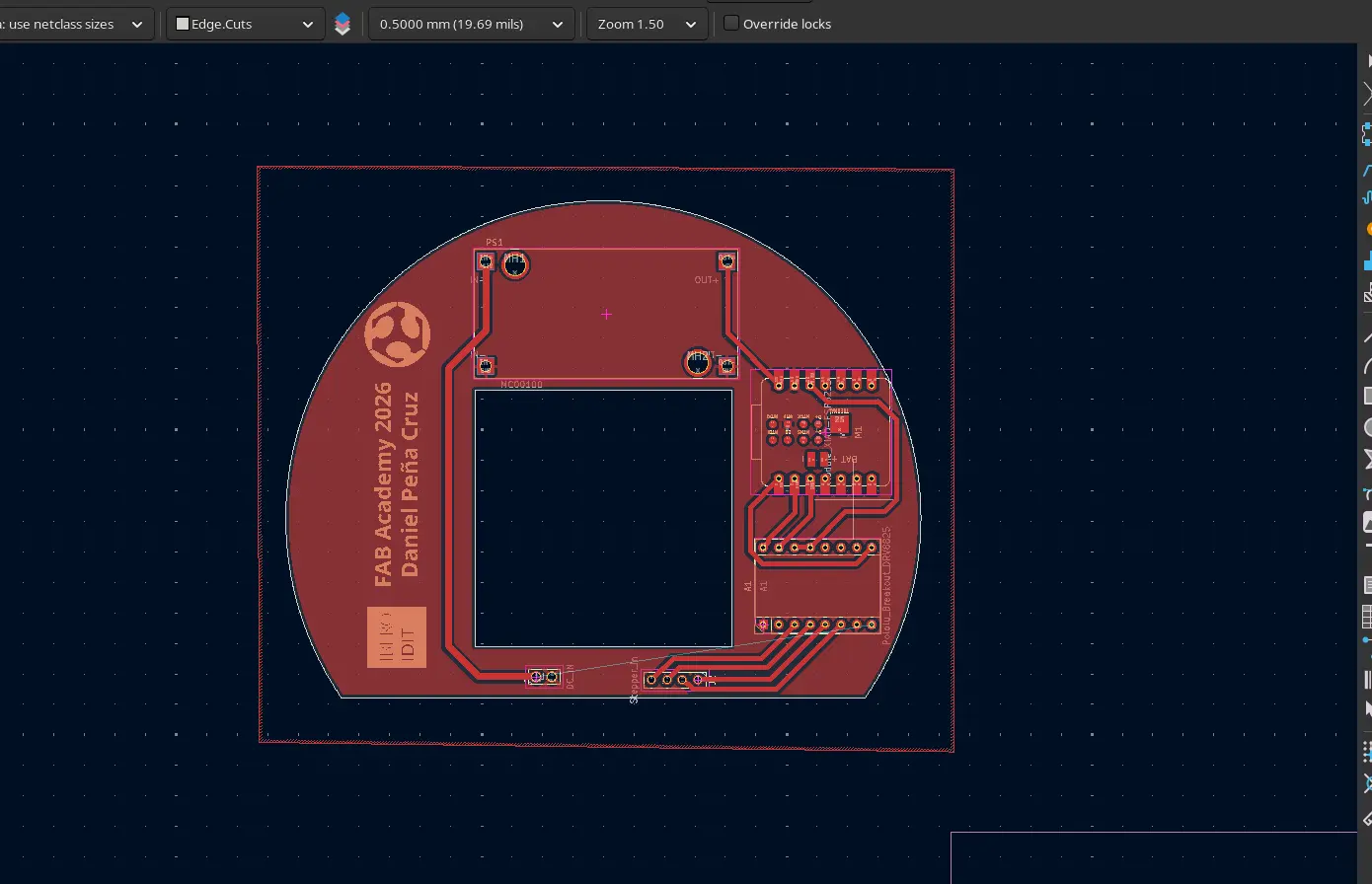
It is important to note that this might not end up being the final PCB used in my project. It is just the first iteration, that should allow me to start every other step of the process that requires this PCB. Other than that, it is just a matter of producing. Any updates made to this PCB will be listed underneath this same section.
May 7th
PCB Production
I produced this PCB in the XTool F1 Ultra of our lab. It seems like I’ve become the “master of the laser” here at our university, at least for PCB production. Being the only student using the XTool for PCB production means that this machine is always available, meaning that I can make multiple iterations of the same PCB in relatively short time. Still, as much as I love this machine for PCB production, it still comes with some limitations:
- Production times are longer than with the Monofab SRM. Considering that this PCB is quite big (11cm in diamter) production times were around 1:30 hours to 2:30 hours.
- I’m still testing my hole perforation values. I’ve already achieve drilling with the machine, but with some burning and trace removal.
If I’m being honest, I do not mind the extended production times, as I use that time to parallel work in other tasks considering that the machine requires minimum supervision. Be aware: Always stay near your machine, and keep an eye on it periodically.
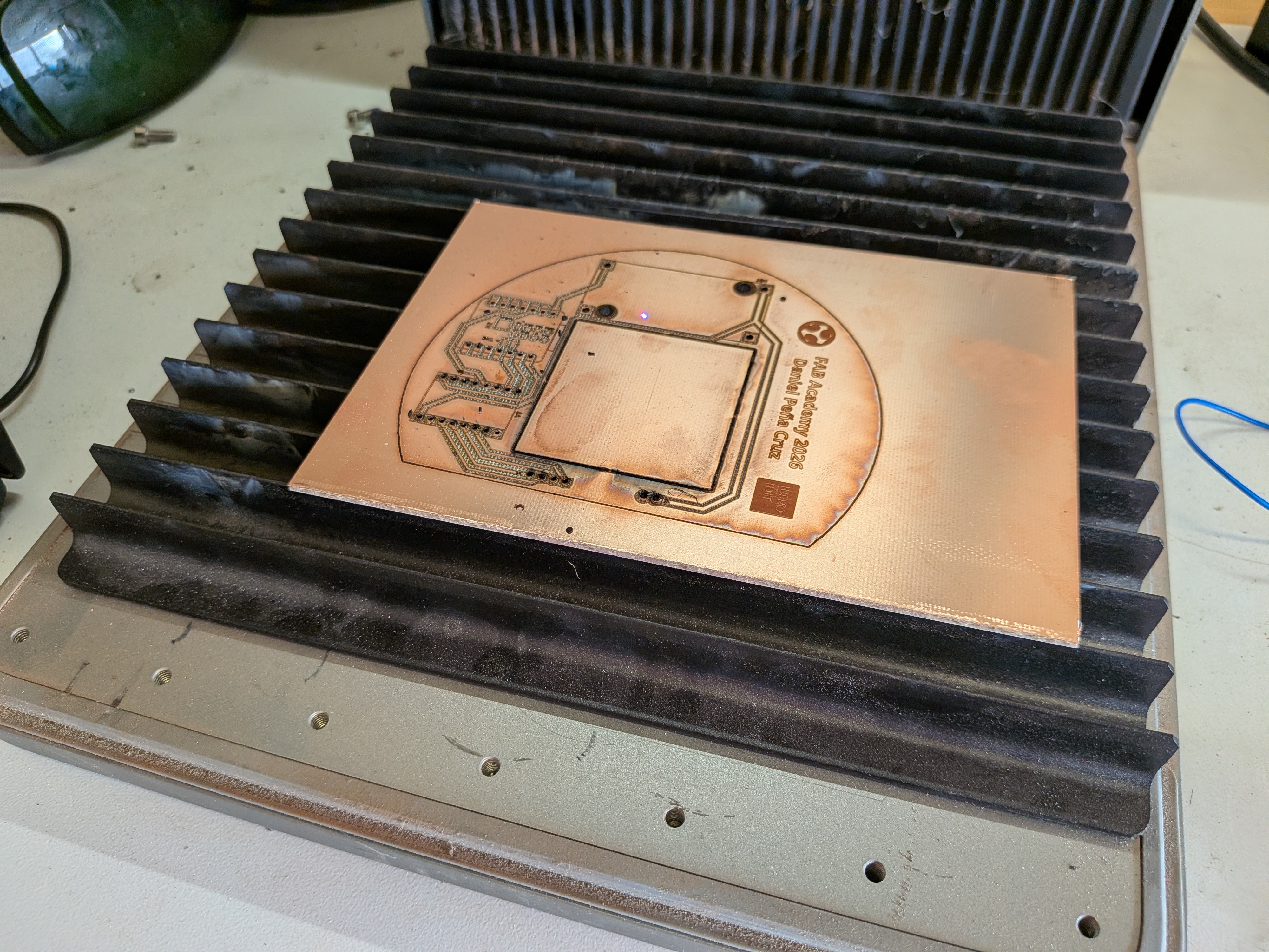
The first PCB I produced had some burnt and removed traces, so I had to redo it. This was fine, as I added some modifications to it. The first one was using the correct footprint for the terminal block I was going to use, plus relocating it to a more convenient position. The second thing was removing that FAB Academy silkscreen. I didn’t realized that adding like that would make them be on the underside of the PCB, not visible to the public. And, considering that they extended my production times by around half an our, I decided to remove them.
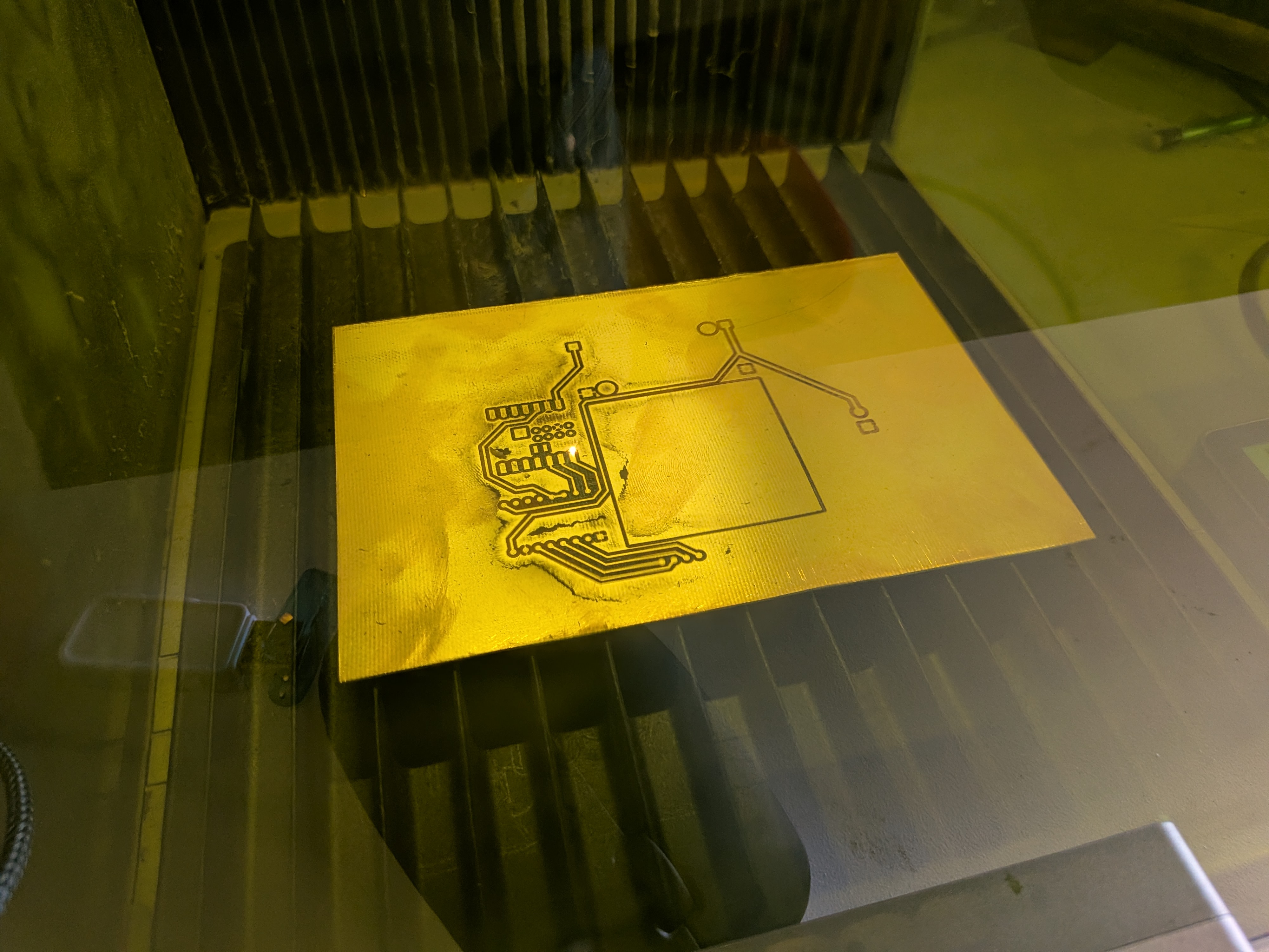
The second PCB resulted with no issues. The copper around some pins where removed, but those pins were unused so no problem there. Using a multimeter, I tested each trace individually to make sure they had no unwanted ground connections (they never do, but I always make sure). Before soldering, I adjusted the buck converter value to have a 12v input and a 5v output (4.97v). I soldered my components to the PCB, and using the multimeter I tested each individual pin coming through the PCB making sure they were correctly soldered. Finally, I connected the PCB to the power supply unit, and tested that every power line was present.
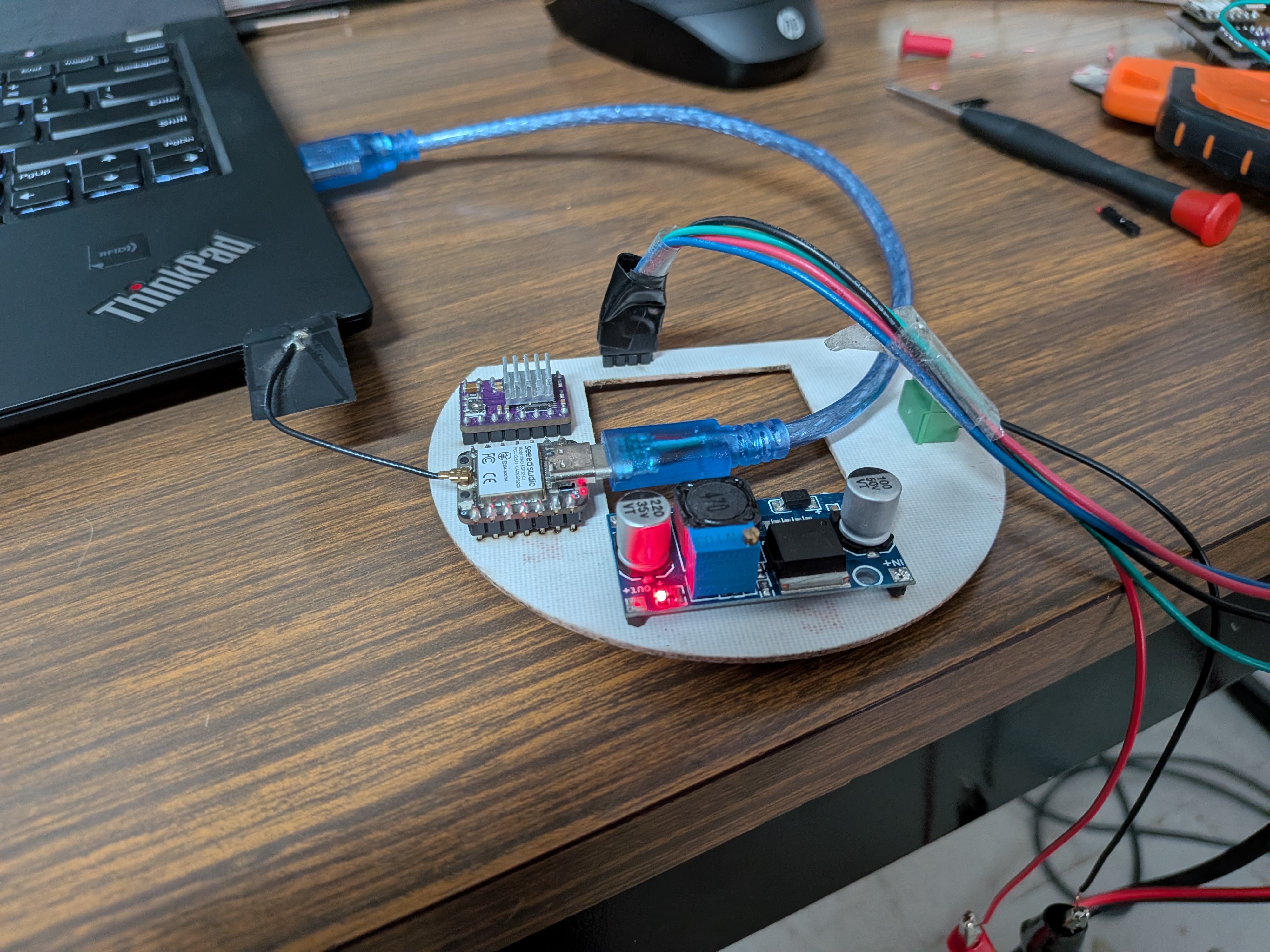
With everything ready, I flashed a testing script into the ESP32C3 on the PCB. This script was my movement script, that would receive UDP data and adjust the position of the stepper motor. I then a person detection script with an UDP sender in my laptop (no physical connection between my laptop and the PCB). The motor moved flawlessly.
The movement is not perfect, some modifications need to be done into the script. The script uses the map() function of Arduino, to map the steps needed for a full rotation of the stepper motor and the value received from the tracking. Adjusting this value conversion should result in a smoother tracking experience. But, as is, the tracking works. Mounting the stepper motor into the rotating base results in the same positive results. Testing showed that the 5:1 ratio proposed wasn’t actually correct, and that we have a practically 1:1 ratio. This is good news, as no conversion to account for this 5:1 ration is needed, simplifying our script.
And with that, the electronics side of the project is basically done. The only thing remaining is the final connection from the stepper motor into the PCB. Other than that, everything else is up and running!
May 22th
Programming
The ESP32
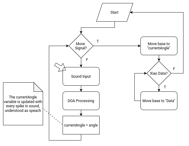
The ESP32 will manage the rotating base movement and the INMP441 MEMS microphone array for the sound detection system. For this, the ESP32 will require the following functions on its script:
- A “Home” function in the setup of the script, to return the robot to its home position. The robot will slowly spin into one direction until receiving a signal from the a3144 hall sensor on the base of the robot.
- A DOA (Direction of Arrival) algorithm That will constantly detect the direction of the incoming sound. This DOA algorithm will be the “idle” state of the micro-controller. This algorithm requires the following considerations:
- It needs to translate the incoming data of the MEMS microphone array into an angle.
- It needs a filter to prevent ambient sound from being processed.
- When a peak of sound is detected, understanding it as a voice detection, the calculated angle needs to be saved into a local variable.
- When receiving the activation signal from the Raspberry Pi 5 (trough UDP), a first movement function should activate, moving to the saved angle.
- When receiving data from the Xiao Sense (trough ESP-Now), a second movement function should activate, adjusting the position to match the data received. When data is no longer received from the Xiao Sense, the micro-controller should return to the idle state.
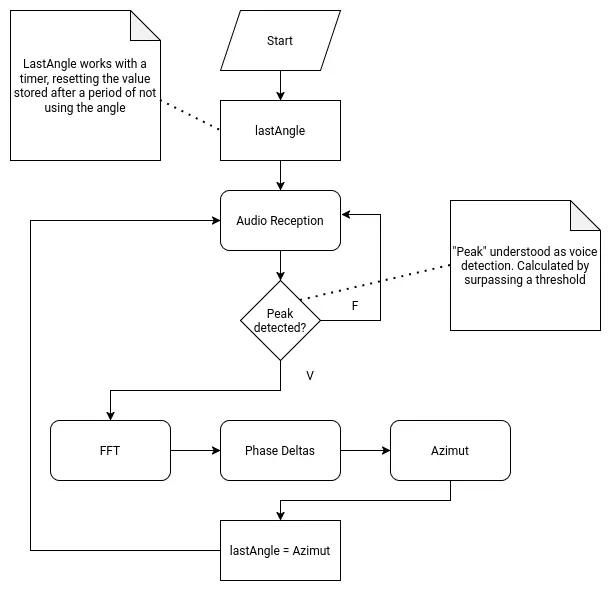
DOA Algorithm
DOA (Direction of Arrival) is the standard algorithm used for determining the overall direction of an incoming signal, in our use case sound. DOA by itself is not an algorithm, but a classification of algorithms meant to return said value. DOA can work in varios configurations.
This means that finding the right algorithm for our use case requires some investigating. The “Bartlett” method requires aiming a straight line of sensors into the incoming signal, changing the angle during the process. When the signal is the strongest, that is the DOA angle. This method wouldn’t work for us as it requires moving our sensors, and ours are stationary. MUSIC (Multiple Signal Classification) is one of the most popular, as well as ESPRIT (Estimation of Signal Parameters via Rotational In-variance Techniques). This can be considered “advanced” methods, as they require some complex mathematical understanding and application to work.
For us, with our microphone array as is proposed, we need “Cartesian” formula. For each axis on the Cartesian plane (X, Y, -X, -Y), there is a microphone. We will first need to calculate the phase difference for each axis. For the X axis:
And for the Y axis:
Then, we would have to calculate Azimut (horizontal angle) and Elevation (vertical angle):
And that would be it. For our use case, Azimut will be enough, as we do not have vertical movement in our robot. In summary, we would need to calculate the phase difference between the sensors in each axis, then calculate the Azimuth. The result of this operation would be the DOA, for our robot to move to.
As complex as it already sounds, it gets a little bit complicated. The raw data received by the INMP441 mems microphone we will be used is not enough for calculating the initial phase difference. We would need to make a DC Offset elimination, Windowing (a function like Hann or Hamming to prevent leakage), and a Fast Fourier Transformation:
Note: This last information was obtained thanks to AI assisted research. The information given might be wrong or incomplete. This information is for demonstration purposes, and to better explain the following point.
Implementing a DOA on our robot would then require:
- Obtaining individual I2S values from our INMP441 mems microphones.
- Applying formulas (mainly Fast Fourier Transformation) to the I2S data to get phase values.
- Getting each axis phase delta (difference).
- Obtaining the Azimut using the formula above.
Then, to complete our proposed script for the ESP32, we need to save that value in a variable, until the wake up word signal is sent to the ESP32. Also, we would need a way to distinguish a voice sound to an ambient sound, and then apply the DOA algorithm to just that value. We would also need a way to constantly update the value for each wake up word.
Needless to say, writing a DOA algorithm for this project would be hard. After some thought and consideration, I decided that implementing the DOA in my project is out of scope for this FAB Academy 2026. I just don’t have the enough understanding of the mathematics and, maybe, the programming skills needed to achieve this. Plus, the DOA algorithm would enable the second most crucial element of my robot, which is the initial base rotation. If not done correctly, the robot would spin to a wrong direction, or to a just slightly off angle that the Xiao Sens wouldn’t detect a person. The point is that, whilst theoretically plausible, it would require time, which I don’t have much of. For this reason, I’ve updated the priority chart on the systems section of this page, to get the person tracking system a greater priority than the DOA system. I decided not to scrap it like with the servo tentacles yet, as there is still a chance that this functionality can be implemented.
May 7th
The Xiao Sense
The Xiao Sense will manage the person tracking system of the robot. The Xiao Sense needs a person detection vision model. This model can be directly downloaded from the Seeed Studio page, allowing for implementations on Platformio or Arduino. For Arduino, the Seeed Arduino SSCMA library is also suggested. The Xiao Sense will also requiere the following functions on its script:
- Implementation of the vision model into the script.
- A first person detected lock that prevents more than one bounding box from being created.
- A function that calculates the aproxímate position of the person on the X axis.
- Data sending function to the ESP32 (via ESP-Now). The Xiao will send the calculated position value to the ESP32 until receiving the “stop” signal.
- Data receiving function from the Raspberry Pi 5 (via UART). When receiving the “stop” signal from the Raspberry Pi 5, the Xiao Sense will stop sending data into the ESP32.
Person Tracking
Our project requires our Xiao Sense to track the position of the first person detected by its loaded detection model. This data should then be sent to the ESP32, which will then adjust the position of the rotating base to the center of the x coordinate of the bounding box created on that person. Plus, the Xiao Sense needs to receive and “On” and “Off” signal from the Raspberry Pi 5, as to stop tracking when the “conversation” is over.
The Xiao Sense is the ideal micro-controller + module combo. The Xiao ESP32s3 its a really powerful micro-controller by itself, but adding the OV2640 module converts it into a small yet capable camera.
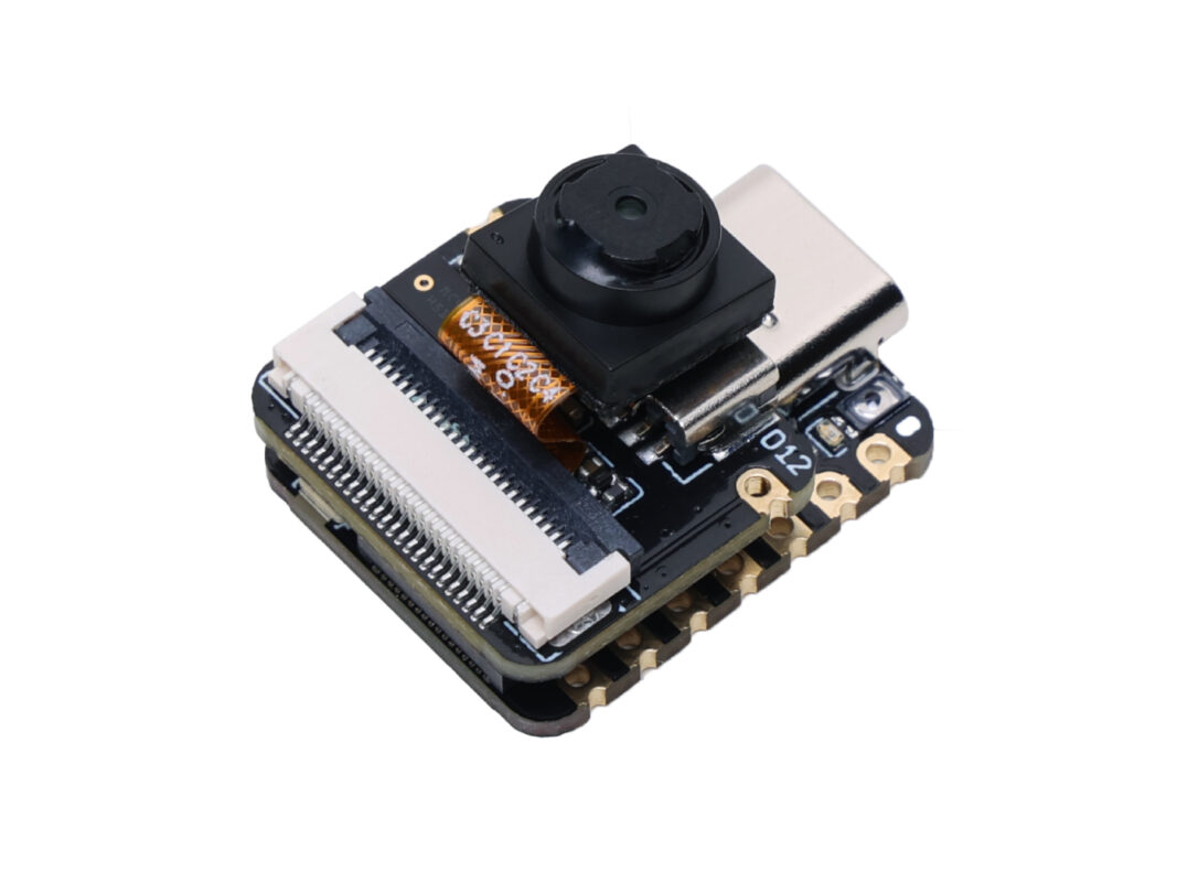
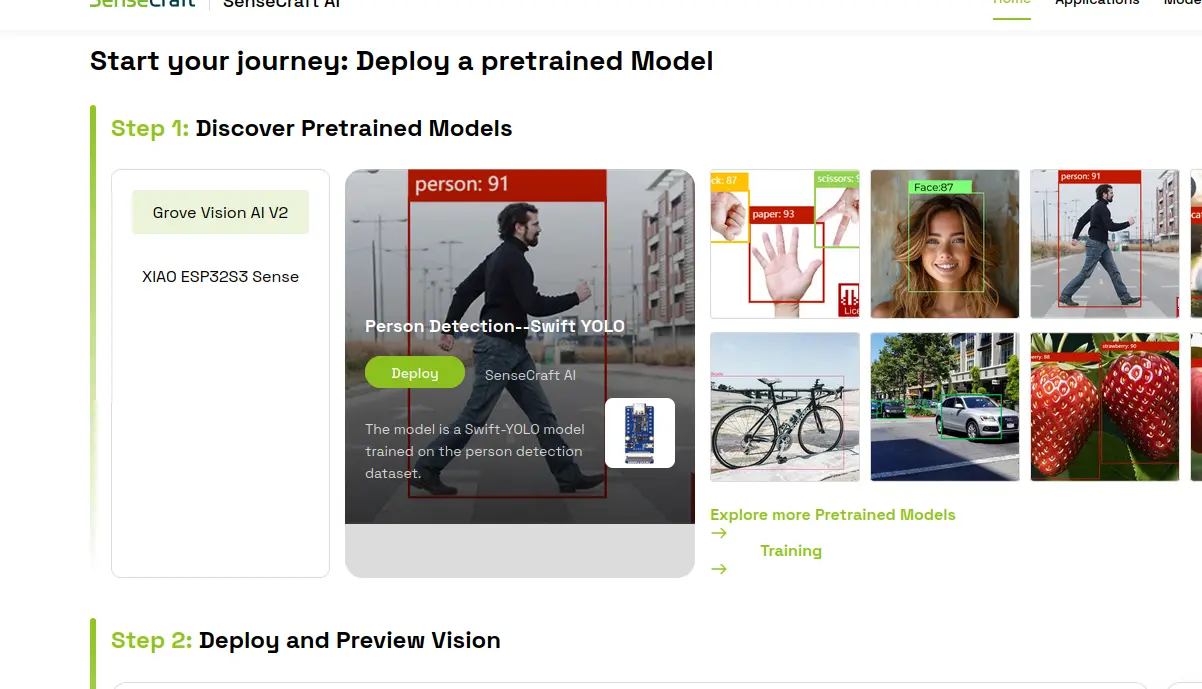
We can start doing some person tracking (and other kinds of tracking) out of the box! We will be using a platform called Sense Craft, a “no code edge AI” platform. Edge AI refers to any kind of AI that is integrated “near” the user, or as part of the product the user is interacting with. Sense Craft allows us to flash pretrained detection models to the Xiao Sense. Using the camera module, the Xiao Sense captures video, processes it and returns data which we can then use for our applications. To start using the Sense Craft platform, go to the page linked above.
Note: Not every browser is supported for the following steps. Google Chrome is the recommended browser by the Sense Craft team, so we’ll be using that.
Click on “Start now”. You will be sent to a new window with a bunch of detection modeles listed. You can choose from any of those models, or even explore more options in the “Explored more pretrained models” link. We will be using “Person Detection - Swift YOLO” model (the one with the guy walking). Make sure to have the “XIAO ESP32s3 Sense” toggle selected, otherwise the following steps won’t work.
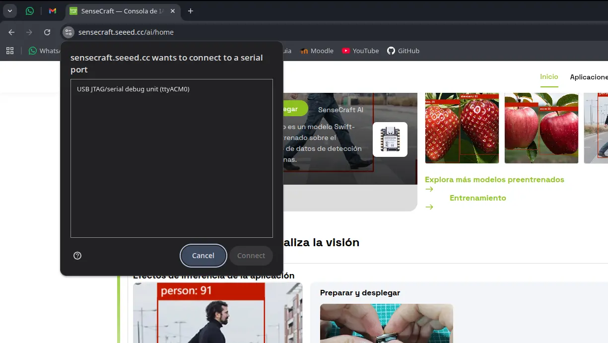
Now, connect your Xiao ESP32s3 to your device using an USB cable. Make sure this USB cable allows for data transfer. Now, in the step 2 section of the page, click the “deploy” button. A pop up window might appear asking you to select the port on which your device is connected. Most of the times there will only be a single port, select that one.
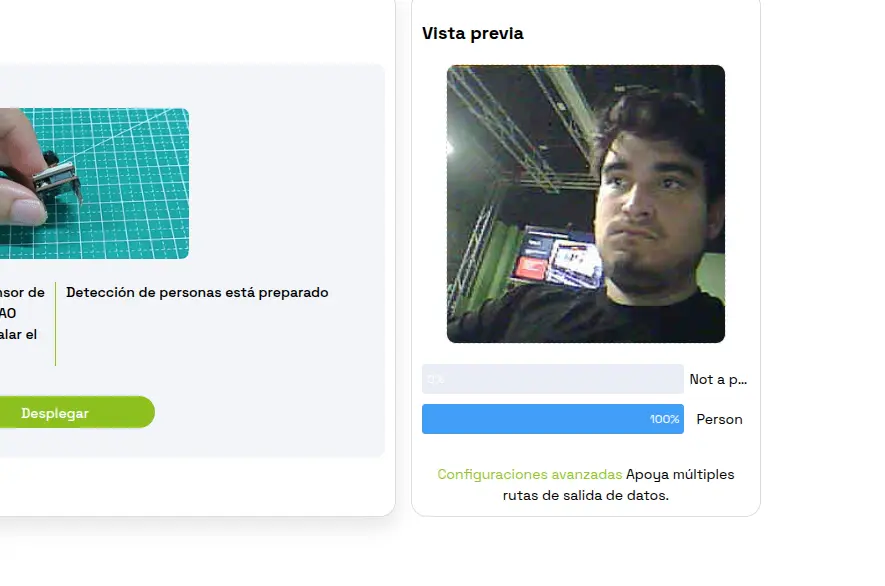
Now, we wait. We will now the model is flashed into the Xiao Sense when a camera view start on the right side of the page. We can now play with our camera! I recommend trying out the different models Sense Craft has to offer, it is a great playground for AI and machine vision.
What really interests us now is the flashed code into our Xiao Sense. In theory, the Xiao Sense is now sending its data through Serial. This means that, if we connect the Xiao Sense into, say, the serial monitor of Arduino IDE, we can se that data appear live. Tuning into Baud 115200 on Arduino IDE, with our Xiao Sense connected, we can see this data being transferred in a JSON format.
We can now clean this JSON, getting rid of every bit of information except for the bounding box data, and send it to the corresponding systems in our robot.
The Problem With Sense Craft
Sense Craft is a great tool to learn about edge AI and build quick prototypes. However, our robot requires extra functionality from the Xiao Sense that just the flashed contents of Sense Craft won’t do. For starters, we proposed ESP-Now as a way of transferring the data compiled from the person detection. We also proposed a Serial “switch” functionality, from which the Raspberry Pi will tell the Xiao Sense to start/stop tracking. For these functions to be implemented, we need access to the source code flashed into our Xiao Sense. The problem is, we do not have access to that source code. Sense Craft does not make public the code they flash into our devices. Why? That’s not their purpose. Sense Craft is a playground. For more “personalized” functionality, additional development is needed. Sense Craft offers a “Software Customization” service, but it is out of scope for the purposes of this FAB Academy 2026.
We could always try to work with the “stock” model we already downloaded. We’ve already tested how the data can be retrieved by a Serial port, which means that a simple receiving script in our Raspberry Pi 5 should be able to get that data. Even if we ignore all the lack of key functionality we’ve already listed, this solution is still sub optimal. The one problem with this solution is that the Sense Craft model is trained to detect every person it encounters, drawing multiple bounding boxes. For us, that we are trying to track a single person, this will break our rotating base logic. This comes without mentioning that, when testing, the detection would linger in spots where a person is not even present, giving a false positive detection.
Why Not Our Own Script?
Without access to the source code of the detection, the idea of creating our own comes into mind. To do this, we would need a tiny machine learning model trained for person detection. Then, we would need a way to access the sense camera from our source code. There is a library called “Seeed Arduino SSCMA”, meant to be used as a way to facilitate hardware interaction and data processing coming from our camera module. However, I was not capable of getting it running. It appears there is a compatibility issue with newer versions of the “ESP by Espressif Systems” board manager library. Downgrading the esp library to a compatible version, but downgrading always comes with more issues.
Even if I were able to run the “Seeed Arduino SSCMA” library, I’d still need a way of processing the person detection. Tensorflow, a widely used library for machine language and artificial intelligence applications, has a smaller version called “tflite-micro”. You can find this micro version of Tensorflow on Tensorflow’s official GitHub repo. However, using this version of Tensorflow is quite harder that using regular Tensorflow, an already complex library. Remember, this micro Tensorflow will be working with a limited storage, where it plus the model and the rest of the script need to live. Tensorflow is not the only option. YOLO, a machine vision and AI detection framework (You Only Look Once), should technically be possible to use, as the name of our test model on Sense Craft implies it runs with YOLO. And whilst I have some very few notions about YOLO, I have no idea on how to condense it and flash it in a Xiao Sense.
Repurposing The Xiao Sense
For all the reasons listed above, I was in a different position. The Xiao Sense person detection system started to look like the DOA Algorithm problem all over again. Solving the issues around having this system seem too complex for the amount of time I have. But, after some thinking, I came up with a smart solution: The Xiao Sense will become just a camera.
The problem with the person tracking system was that all the processing should be done inside the Xiao Sense. But what if the Xiao Sense doesn’t handle it? I already have a script that does person detection with OpenCV (OpenCV runs in the OS layer, meaning it is not an option for the Xiao Sense, by the way). If we load that script into the Raspberry Pi 5 it can handle it without issues (more on that later). But now the Raspberry Pi needs a camera, and the Xiao Sense is still the smallest camera we can get our hands on.
This solution not only solves our person detection system: it also keeps our Xiao Sense in play.
Note: Sadly (at least at the time of writing this), I have not found a “clever” solution like this one for the DOA algorithm system. This is why the person tracking system hasn’t been given a lower priority. If at any point of the development of the project I find a solution for the DOA algorithm problem, I’ll be happy to integrate it back into the robot.
Web Camera
With this new change of plans, we face 2 new problems:
- We need a way to transform the Xiao Sense into a usable camera for the Raspberry Pi.
- We need a way to use this camera in our python tracking script.
The second one was easy. We just modify the video_capture = cv2.VideoCapture(0) function on my script. This function creates the video capture object for OpenCV to use. The “0” as argument states that we will be using the default video capture device in our laptop/computer, in my case my integrated camera. If we can tell the Raspberry Pi 5 to use our Xiao Sense as its camera, we are set.
For the first problem, though, it took a little bit of extra researching. Initially I wanted to convert it into an “USB camera”, sending the data through a Serial connection between the Xiao Sense and the Raspberry Pi. My research informed me, though, that there was an easier way to achieve this: Web Cameras.
The idea behind this “web camera” method is to tell the Xiao Sense to broadcast its video in a https address, and with OpenCV connected into the same WiFi network, we will grab that https direction as our video entry like this: video_capture = cv2.VideoCapture(<video_streamig_url>).
Our luck continues to get better, as Arduino IDE includes a list of example codes for a variety of micro-controllers, and it so happens that one of the example codes for the ESP32 platform is a web camera code. To run this code in Arduino IDE, we need to navigate to Files > Examples > ESP32 > Camera > cameraWebServer.
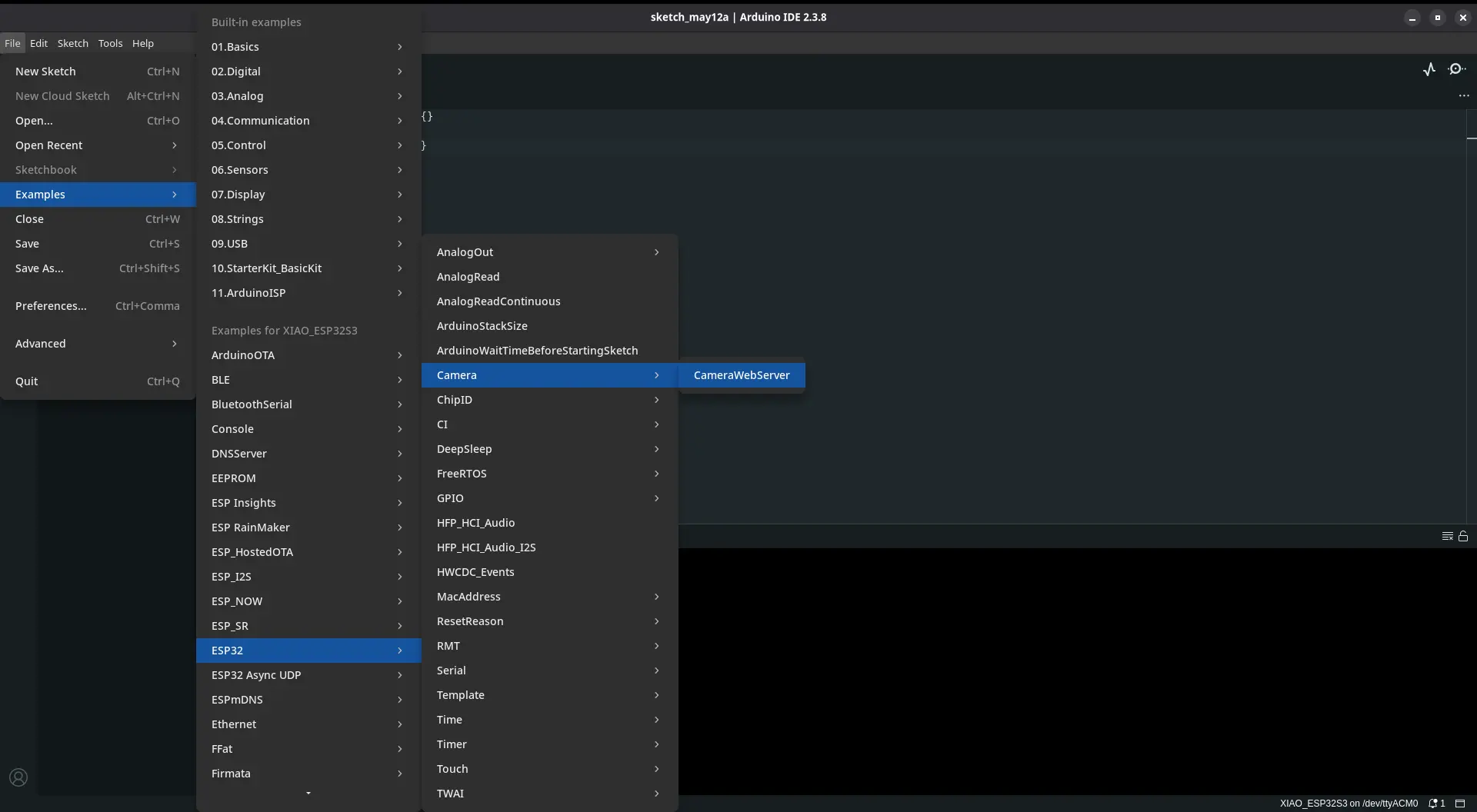
Now, we navigate to the “board_config.h” file in our file tabs. We need to comment out the uncommented board, and uncomment our “XIAO_ESP32” board. Now we only need to flash this into our Xiao Sense. After the flash, the serial monitor should print an https direction. We need to copy it. Returning to our script, we need to add this url into the video capture object, as the only argument. Now, we power up our Xiao Sense, wait a little bit for the internet connection to boot up, and we can run our python script.
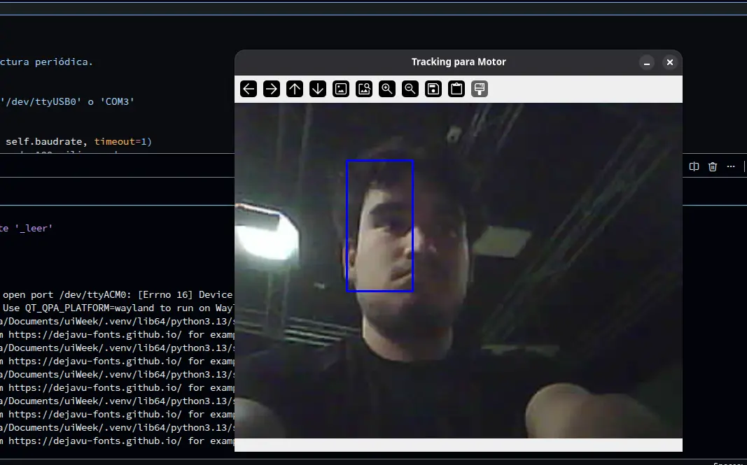
As you can see, we have successfully created a web camera! The quality of the video is way better than the one with the Sense Craft example. This solution proved to be the best I could have come up with. Not only we gave “eyes” to our robot, we made it in a way that we no longer need an “activation signal”, as the tracking is completely controlled in the same code base as the AI scripts.
There is one issue remaining: the Raspberry Pi 5 will now need to run the AI script and the OpenCV tracking script, both at the same time. In theory, using thread should solve this problem. In our script, we can tell the Raspberry Pi 5 to designate one of its 4 cores to a dedicated task. One core for the OpenCV processing and the rest for the AI processing. This distribution is just an example, and I still don’t know if running both functionalities in separate threads will solve the problem.
May 12th
With the threading implementation on the Raspberry Pi 5 script, both the person tracking and the AI processing can be accomplished at the same time, giving us green light to implement our web camera into the project. The idea stays the same: the tracking script on the Raspberry Pi 5 uses the Xiao Sense ESP32 Web Cam (from now on only Xiao Sense) as the video source. The images streamed from the camera are processed and, when a bounding box is created into a person, we send that data through UDP to the rotating base.
Our first test where not as processing as expected. The Xiao Sense’s limitations became really obvious. The first series of tests where just processing the person detection without sending data. During this tests, the Xiao Sense under performed, with a reduced amount of frames, skipping a considerable amount, false positive detection due to the low resolution of the camera, and overheating. Overheating was expected, I new in advance that Xiao ESP32S3s with the Sense module operate at high temperatures. My first hypothesis was that overheating could be causing this performance issues, considering that the camera needs to use processing power to send data through its HTTP protocol. Using a Xiao Sense heat sink on the back of the ESP32S3 did not fully solve the issue, so my hypothesis might be wrong. The other remaining culprit could be the OpenCV processing itself. I even adjusted the values on the Xiao Sense script, reducing its resolution by a considerable amount, and the performance was still the same.
Despite the problems I had on those first series of test, I still decided to connect everything for a first full implementation test. As expected, the rotating base was receiving partial data from the person processing script. Removing the Xiao Sense from the equation and using my laptop’s camera, the whole system worked flawlessly. The rotating base adjusted its position to my tracking, and data was constantly being transferred at real time through UDP. This means that the bottle neck of the system is the Xiao Sense.
We’ve reached a yet another turning point on the development of this project. Implementing the Xiao Senes as the video source for the tracking script will require one of two solutions:
- Changing the strategy, and converting the Xiao Sense into an USB camera.
- Keep the Web Cam approach, with performance optimizations.
Out of the two, the second one seems more reasonable. Converting the Xiao Sense into an USB camera will require further investigation (and headaches), as it appears that there is no official method or library to achieve this goal. The same problem of “not compatible” ESP32 libraries I’ve been having during all this project’s development (and all this FAB Academy if I’m being honest) will repeat for sure.
However, keeping the Web Cam approach with even more optimizations is not as easy as it sounds. Remember, the Xiao Sense is still under performing even with those initial optimizations (reduced resolution mainly). Reducing the values of the streaming further comes with some risks: the more we reduce the video quality the less precise the person detection will be, increasing exponentially the amount of false positive detection. In theory, there must be a “sweet spot”, where the quality of the video is optimized enough to reduce the false positive counts and also stream a constant video to the tracking script.
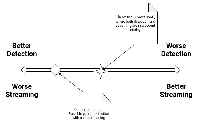
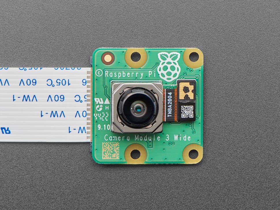
As of the time of writing this, there is no current solution to the problem. Further tests will be made to try and find this theoretical “sweet spot” in the Xiao Sense’s configuration. As a plan B, using another type of camera could be considered. The Raspberry Pi 5 has a camera module, but we don’t currently own any and buying them is not a possibility at this time. We have camera modules for the Raspberry Pi 4, but their FFC (Flat Flexible Cable) type is not compatible. Another ESP32 based camera could also be considered, depending completely on availability in our lab.
In the worst case scenario, the Xiao Sense camera will need to be scrapped, and with that the person detection system. I’ll do anything in my power to prevent this from happening. Still, I’ll be preparing a “contingency plan”, as scrapping the person tracking system from the final project means that the rotating base will be out of purpose, and almost all systems proposed on the original sketch of the project will have been removed. I’ll only reveal this contingency plan if necessary.
May 22th
Raspberry Pi Camera
Thanks to my instructor and his vast arsenal of tools and gadgets for us students to use, I got my hands on a Raspberry Pi Camera module. This camera modules are designed to connect directly into the Raspberry Pi with a flex cable, to a dedicated terminal on the Raspberry Pi 5. Using the correct flex cable for our Raspberry Pi 5 model, we should be able to get a relatevely plug and play experience. Is this the most “FAB friendly” solution? No. But, to be fair, this would be the most appropiate solution for capturing video into the Raspberry Pi 5, specially for Machine Vision applications like this one.
With the Raspberry Pi 5 off, I connected the Raspberry Pi Camera in the corresponding terminal. The Raspberry Pi 5 has two camera ports actually, it is usually recommended to use port 0. After that, I turned on the Raspbery Pi. I loaded up my tracking script, this time changing the video capture source from the ESP32 Web Cam URL to 0, or the system’s default camera. I ran the script and it returned an error. This error stated that there was no camera device detected. I honestly expected this, as the Raspberry Pi 5 has no camera by default. I needed to configure camera.
Here’s where things started to go wrong. Apparently, with the last version of Raspberry Pi OS (Bookwork) the library that manages cameras changed names, from “libcam-hello” to “rpicam-hello”. This shouldn’t be an issue, I just needed to install the new dependencies. I ran sudo apt update && apt install -y rpicam-apps. This command refreshes our packages and instals (without need to confirm) all the rpicam dependencies. Now, if we just run rpicam-hello --list-cameras to see if our camera is being detected. However, running this command resulted in a “No devices available” error. This means that our camera is not being detected correctly.
I started researching on how to solve this problem. I was sure that the problem had nothing to do with the physical connection of the camera to the Raspberry Pi 5, as I checked that multiple times. I found this YouTube video by the BMonster Laboratory channel, with a step to step guide on how to solve this problem. His guide involved installing some drivers for the Raspberry Pi 5 to detect the camera. To be honest, I didn’t expect the Raspberry Pi 5 to need external drivers to use this Raspberry Pi branded camera, but it seemed like my current situation required it. I followed the tutorial to a tee, but it didn’t solve my problems. Then, I tried multiple debuging things. I ran sudo rasp-conf on my terminal to enter the Rasbperry Pi 5’s configuration UI. I turned on i2c, as the camera requires it to communicate with my Raspberry Pi 5. This did not work. I disconnected my MEMS microphone and removed the lines on the firmware configuration that trikced the Raspberry Pi 5 into thinking it was a google voicehat. I did this because I though there might be issues when having both running, but it also didn’t work (which was a releaf, as if that was the case, my microphone and camera could not work togheter meaning I needed another solution for either one).
Then I dug deeper on forums trying to find information on why my Raspberry Pi 5 wouldn’t detect the camera module. Apparently, this issue could be cause by either one of these problems: The first one being library compatibility issues with libcam-hello and rpicam-hello. As I said before, with the latest version of Raspberry Pi OS, what used to be the camera library was updated, changing its name and, most likely, key parts of its functioning. This means that the way the Raspberry Pi 5 interacts with the camera has also changed, leading to problems. I’m well aware of this problem, as here at Ibero Puebla’s LIARE we have a Raspberry Pi AI hat, an AI acceleration module for the Raspberry Pi 5. A friend of mine was in charge of getting it running, but he always complained of compatibility issues between libraries, as our AI Hat was designed to work with older versions of some libraries. The second one being the Raspberry Pi OS version I choose. Apparently, the camera module has issues with the x64 version of the OS, and according to some users on the Raspberry Pi Forums, using the x32 version could solve the issue. This requires a full reinstall of the OS, and the risk of other things I’ve already built breaking with the architecture change.
The only other thing that could be causing these problems is the camera/flex cable itself. There is always the possibility that the flex cable is broken from the inside (an issue I’m well familiar with, as I sometimes do laptop repairing as a hobby). I don’t think this might be the case, considering the little to no use this camera module has seen. In any way, the Raspberry Pi camera is not working, meaning that the Xiao Senes is our best (and only) camera option. I will keep on trying to get the camera to work, but I’ve already made up my mind that this is not going to be an option to replace the Xiao Sense in our project.
May 26th
The Raspberry PI 5
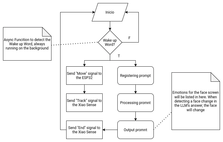
As the main brain of the robot, the Raspberry Pi 5 needs to handle two main functionalities. The first one being the LLM hosting and supporting functions. The second one being signal sending to the other micro-controllers. Both of these functionalities will be hosted on a single main file, as to allow them to coordinate and communicate with one another.
The following flow chart describes the main function:
Getting Started
To start using our Raspberry Pi 5, we first need to create our installation device. For this, we need an SSD card and the official Raspberry Pi Os image creation tool. You will also need a keyboard, mouse, monitor and an micro HDMI to HDMI cable. Also, make sure that the Raspberry Pi has a ventilation module installed, either the casing ventilation or the Active Cooler module. If you do not have a cooling system on your Raspberry Pi, operation times will slowdown drastically, and you can even harm your board.
When the image creation tool is installed, connect your SSD card to your computer and start the app. Once in the app, follow the installation process. Select “Raspberry Pi 5” as your board, then select “Raspberry Pi Os (64-bits)” as your operating system. Your SSD card should be the only available device to install, select it.
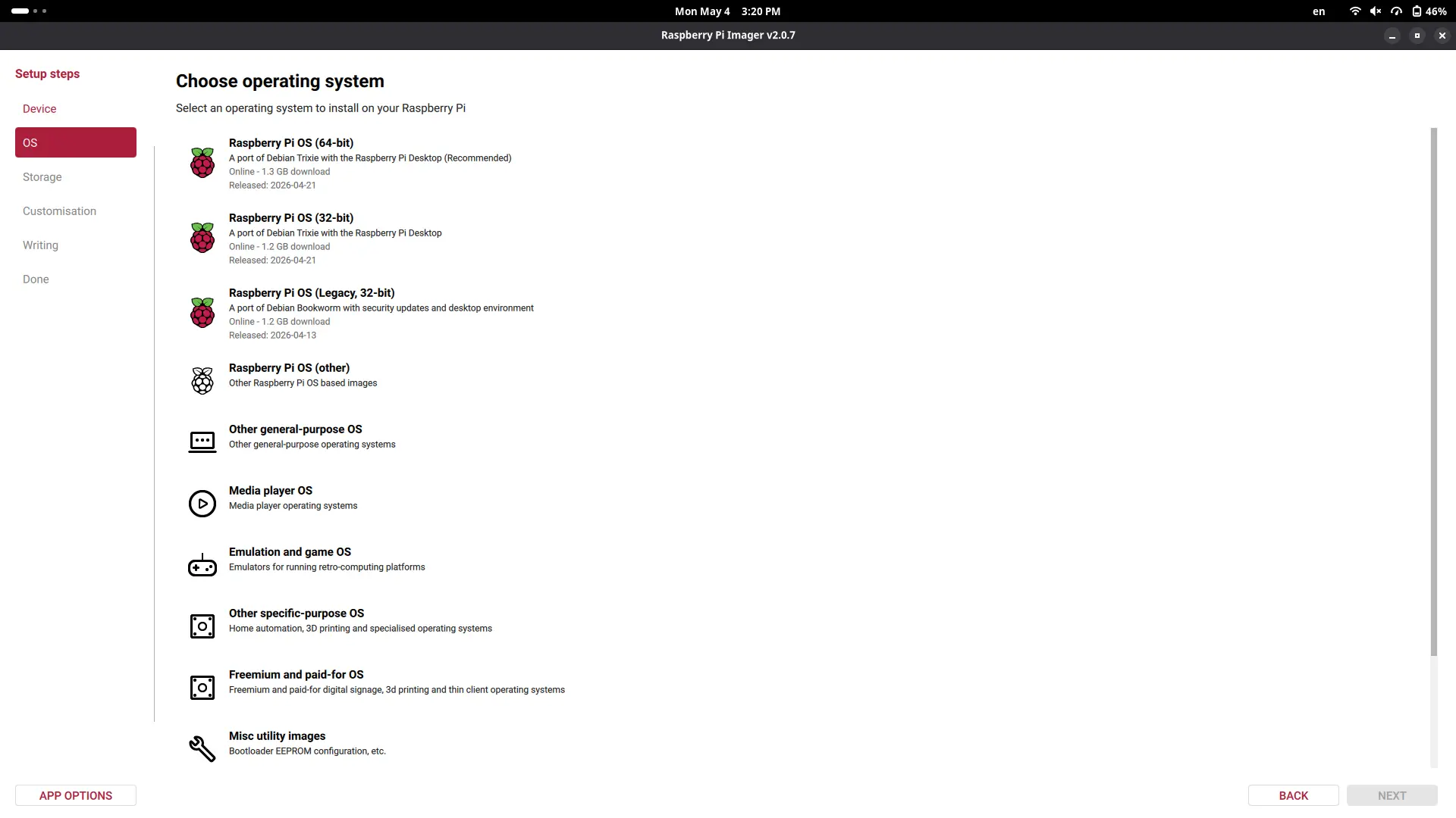
Now, customize your Raspberry Pi as you wish, adding your device name, user name, password, etc. Anything you don’t understand, like SSH connection or Raspberry Pi Connect, leave unselected. Your OS will begin to be written into your SSD card.
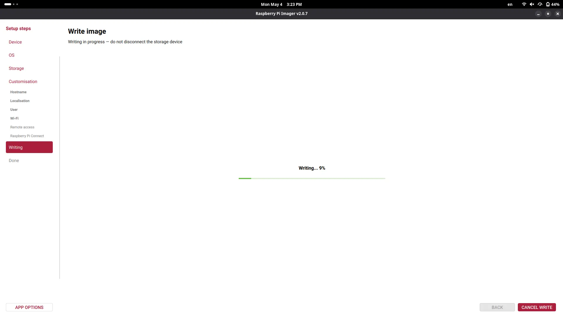
Once the process is finished, unplug the SSD card from your device, and place it on the SSD card holder underneath the Raspberry Pi. Once the SSD card is properly placed, connect the Raspberry Pi with its official power supply charger and click the power button on one of its sides. We can also connect the keyboard, mouse and screen to our Raspberry Pi.
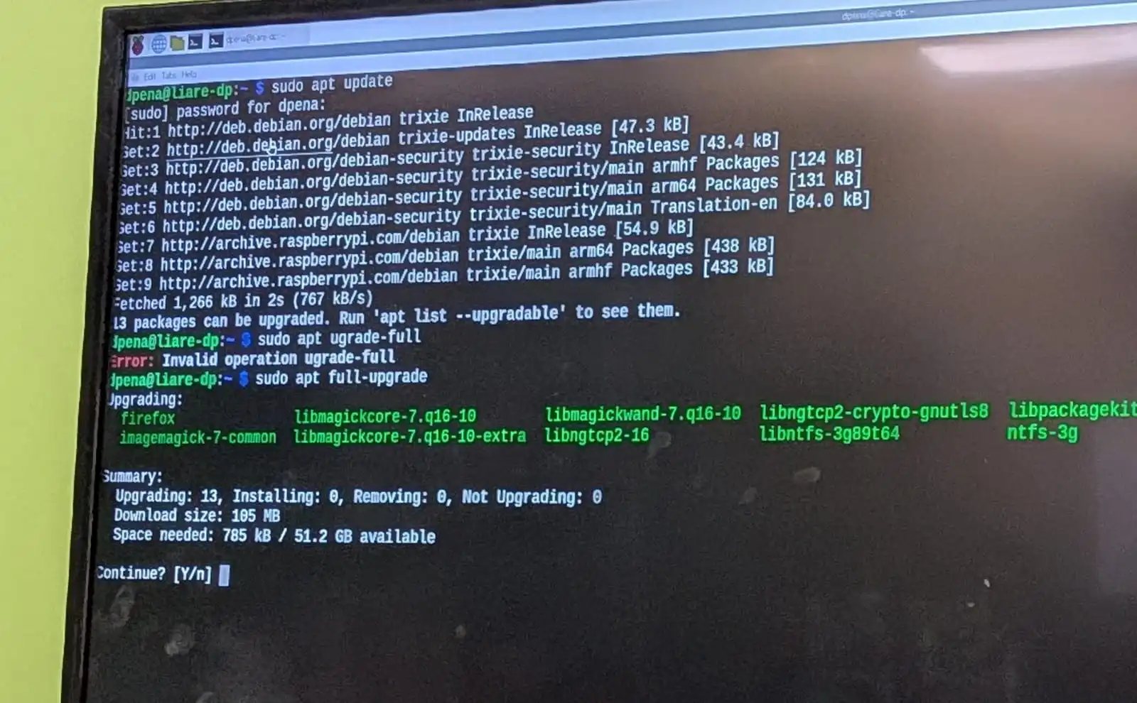
The first step to make once we see our desktop is to open our terminal and run sudo apt update and sudo apt full-upgrade. Sudo is the administrator permission manager of Linux. It will ask you for your password, the one you created when configuring your OS in the image creation tool. The first command will refresh the repositories installed on your OS. It is a good practice to run this command before any installations. The second command will update our OS to its latest version. After this second command finishes, run sudo reboot to restart your system and apply any changes.
The easiest way to get our already developed scripts into the Raspberry Pi is to publish those scripts into a GitHub repository and clone it into our Raspberry Pi 5. You can choose your favorite method, I went with this one. The script we are using can be found in the AI section underneath this page.
Ours AI script as is does run on the Raspberry Pi 5, but not exactly. See, here’s where that power difference between my laptop and the Raspberry Pi 5 really came to light. The Raspberry Pi 5 took about 20+ seconds from the moment I said my prompt to the moment it started the text to speech answer. Running htop on our terminal lets us see our device’s CPU usage. During the script execution, the CPU values on all of the Raspberry Pi 5 chip cores maxed out at 100%. This means that our CPU entered a “throttling” state, reducing its overall efficiency to prevent over heating.
There are two possible candidates as to what is causing the CPU throttling:
- The LLM model is too big.
- The python script is not optimized.
For the LLM, I tried changing it to the “qwen3.6:0.5b” model, a quantize model. Quantize models are “really compressed” models design for almost instant answers, at the cost of less functionalities and power. The python script required a lot more optimizing. Specially on how the sound to text script worked. Essentially, our initial script processed everything at the time. This is no problem for my laptops CPU, but for the Raspberry Pi 5 CPU it is not ideal. I needed a way to decompose the processing of the audio in different threads of the CPU, reducing the overall compute load on it. Using threads with other types of computations is ideal, but for audio processing it requires extra steps as to not harm the quality of the audio.
The other thing we can do to upgrade our performance is to enable ZRAM in our Raspberry Pi 5. ZRAM is a method of compressing the RAM contents, virtually increasing our available RAM and making our processing faster. To install ZRAM into our Raspberry Pi, I followed the official Debian Wiki Page on ZRAM installation.
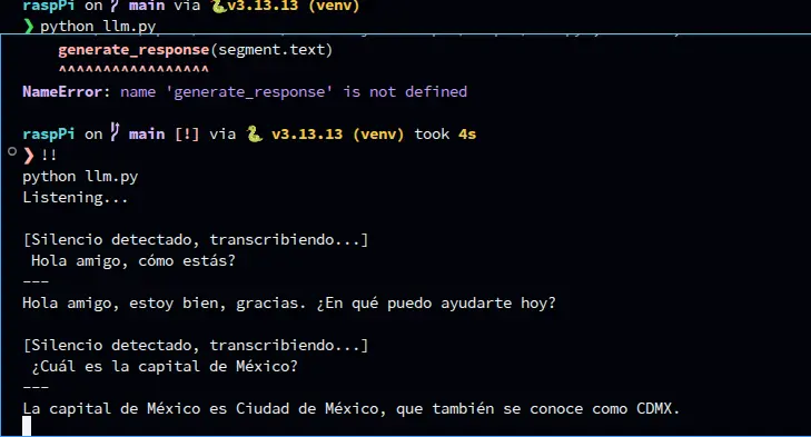
To be honest, I had no idea how to approach this code optimization. I ended up using AI assistance to optimize my code. Most of it remained the way I coded it, with some extra modifications on the speech to text. This modifications made it so that chunks of the audio where processed at the time and sent to the text to speech individually, instead of processing the whole audio and then sending it to the text to speech. Running this new implementation worked flawlessly, giving near instant answers at best, and a couple seconds delay at worst, mostly for bigger answers. For me, this shows the real power behind AI assisted coding. AI is a tool that the programmer uses to become an even better programmer.
In summary, we now have an optimized version of my initial code base, that executes the AI functionality of my robot perfectly. The only thing I would like to test is returning to the original “llama3.2:1b” model, hoping that the new improvements to the code base will allow it to work properly. If not, “qwen3.6:0.5b” works well too.
May 6th
AI
Getting started with the AI part of the project is best to be done on the actual Raspberry Pi 5 you will be working with. If there is no access to a Raspberry Pi 5, doing it on a personal laptop or computer is also possible. There are a few considerations to take from this last aproach:
- Your LLM model will be faster.
- Your LLM model can be bigger.
- Any scripts attached to your LLM model will run faster.
Even though these sound like a good thing (because they are), it necessary to keep in mind that this kind of performance can only be achieved in a laptop/computer. By design, the Raspberry Pi 5 is slower, less powerful with worse specs than a laptop/computer. The Raspberry Pi 5 is a really powerful tool, but we cannot expect to achieve the same amount of performance from a laptop/computer in our Raspberry Pi 5. There is a limit to the Rasp’s power, and some optimizing will be needed to achieve its maximum performance.
With that said, my first approach to the AI development part of the project was in my own personal computer.
Ollama
Ollama is a free platform for locally hosting LLMs in a personal device. Ollama hosts a vast catalogue of LLMs for us to chose, some of them big, some of them small, some of them with dedicated purposes like coding. We will be running on a limited hardware, so choosing a smaller model from the get go is ideal. After some research I decided to go with “llama 3.2”, more specifically the “llama3.2:1b” version. This model excels at multilingual knowledge retrieval, plus being in the perfect sweet spot between power and size.
Installing Ollama
To start using Ollama on your device, simply go to the Ollama Download page and select your operating system. Ollama an be installed with a dedicated installer, or by pasting the given command on your system’s terminal. I recommend using the terminal method regardless of your operating system, as it will give us some practice for installing it on the Raspberry Pi OS later on.
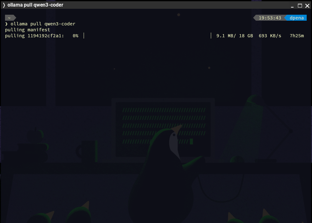
Once installed, we can open up our terminal and write the following command: ollama pull <your_model_name>. This will create an instance of that model on your device. Once installed, you can run ollama run <your_model_name> to start chatting with the model, all in your terminal. To exit the chat, simply type /bye.
As you can see, locally hosting AI is really simple. It opens up a whole word of opportunity for us, like being able to have AI assistance offline.
May 8th
The Script
We will be writing everything needed for the AI part of the script in Python, as it is the “industry standard” language for any AI application, specially for projects like our. As explained on the Raspberry Pi 5 diagram on this page, our script will require 3 main parts: The input, the processing and the output. We already tackled on the processing part with Ollama. However, using Ollama in our script will require some extra steps. For the input side of the script, a speech to text library is necessary. Whisper from OpenAI is the most used library for this department. We will be using the “faster-whisper” python library for this. We will also need some other dependencies for handling the audio input and processing. And at last, we will be using Piper for the text to speech part, more specifically the “piper-tts” library.
To start developing our script, we will firstly need to create our python virtual environment. You can look at how to do this in my week 14 page. Once our venv is created, will will need to install the following dependencies:
- piper-tts
- ollama
- faster-whisper
- sounddevice
- numpy
- scipy
Alternatively you can download the Raspberry Pi scripts on your device, create a venv on the same folder and run pip install -r requirements.txt. This will automatically install every dependency on your venv. This is, by the way, the standard way of sharing python scripts that require dependencies, by creating that “requirements.txt” file before sharing it.
We can now begin with the the processing script. The processing script is, surprisingly, the easiest of them all. Running an Ollama model in python only requires a couple of steps:
Note: The model you chose to use on your script MUST be installed on your device.
        import ollama

        def generate_response(promt: str) -> None:
            response = ollama.chat(model='<your_installed_model_name>', messages = [
                {
                    'role': 'system',
                    'content': '<your_ai_role>'
                },
                {
                    'role': 'user', 'content': promt
                }
            ])

            print(response['message']['content'])

        generate_response("<your_promt>")
running this scripts by itself, we will get an answer to our prompt in our terminal. By itself, this is working AI on python. Now, we need to input our voice and get a voice answer.
Speech to Text
Speech to text with whisper is not as easy to code as the AI script. The speech to text script will require extra code to get our script to work with our device’s audio input. Sounddevice is the most used library for this. I followed the example in this YouTube video by the KARTIS channel, who I personally shout out and thank for. The code is quite lengthy to put in this page, plus KARTIS does an excellent job at explaining their code on their video. The one thing I did add by myself was added a noise filter. This noise filter works like a threshold, any sound beneath the threshold will be ignored, any sound above will be interpreted as words, and returning to a no sound state will trigger whisper, interpreted as stopping to talk.
Text to Speech
Text to speech requires Piper. Using Piper in or script requires an extra step: downloading the voice model we will be using. To download a voice model, go to the Piper GitHub Page and scroll down to the “voices” hyperlink. Go to “Download Voices”, and navigate through the options to select your desired voice. In the same GitHub Page there is also a “Samples” hyperlink that lets you test all the available voice models. For my use case, I downloaded this voice. Once you navigated all the way through your voice folder, you will find two files: an “.onnx” file and a “.onnx.json” file. Download both. Then, on your projects folder, create a “models” folder. This folder is not obligatory to have, but it will help us organize our code base. Place your downloaded files into this folder.
Note: I downloaded a Mexican Spanish speaking voice. There are only two available es_MX voices on Piper, whilst there are a lot of en_US voices. I decided to go with a Spanish speaking voice, as my main user is Spanish speaking.
Now, we can run the following code:
        import io
        import wave
        import numpy as np
        import sounddevice as sd
        from piper.voice import PiperVoice

        model = "models/es_MX-claude-high.onnx"
        voice = PiperVoice.load(model)

        class Voice:
            def __init__(self, model="models/es_MX-claude-high.onnx"):
                self.model = model
                self.voice = PiperVoice.load(self.model)

            def speak(self, texto: str):
                buffer_memoria = io.BytesIO()

                with wave.open(buffer_memoria, "wb") as wav_file:
                    self.voice.synthesize_wav(texto, wav_file)

                buffer_memoria.seek(0)

                with wave.open(buffer_memoria, "rb") as wav_file:
                    frames = wav_file.readframes(wav_file.getnframes())
                    sample_rate = wav_file.getframerate()

                audio_array = np.frombuffer(frames, dtype=np.int16).astype(np.float32) / 32768.0

                sd.play(audio_array, sample_rate)
                sd.wait()
To use this code, we can simply create a “Voice” object instance, and run the speak() function with our text as the argument, like this:
voice = Voice()
        voice.speak("<your_text>")
Main.py
Out “main.py” file will combine all of these scripts into a single function. This combination follows the exact same logic as the diagram above explained:
        import sys
        from tools.speech_to_text import speech_to_text
        from ai import generate_response, reset_conversation

        def main():
        	use_voice = "--voice" in sys.argv

        	print("=" * 40)
        	print(" Octopus AI — Raspberry Pi 5")
        	print(f" Mode: {'Voice + Text' if use_voice else 'Only Texto'}")
        	print(" Ctrl+C to Exit")
        	print("=" * 40)

        	while True:
        		try:
        			texto = speech_to_text()

        			if not texto:
        				continue

        			generate_response(texto, use_voice=use_voice)

        		except KeyboardInterrupt:
        			break

        		except Exception as e:
        			print(f"\n[Main] Error: {e}")
        			continue

        if __name__ == "__main__":
        	main()
This script works as follows: running python main.py will listen to your spoken prompt, process it and return you the answer in text. Running python main.py --voice will do the same, but will activate the voice answer. Separating both functionalities is (text answer and voice + text answer) is ideal for debugging. With this, the AI part of the script is ready. Now, we need the communication functions to speak with our extra micro-controllers.
May 4th
Considering that the threads implementation on the main script was a success, I decided to test once again the performance of the "llama3.2" model. I decided to revisit this model again, as our curren model returns really simple and, sometimes, poor answers. This was to be expected as our "qwen" model meant to be small and run in limited hardware, unlike "llama3.2" which has a good size-quality relationship. I pulled "llama3.2:1b" and changed the model listed on my AI script to be that one. LLama3.2 worked fine, but its answer times where a little bit slower than with the qwen model. I did’t test both the person detection and AI processing scripts at the same time, but performance should be exactly the same because of the threading. I will leave Llama3.2 on, as I prefer better answers with slower execution, as execution can be improved in future developments of this project. Plus, better answers make for a better looking result overall.
May 25th
The Speaker
We’ve already explained how our robot will include text to speech to output its answer to our questions. For that, our Raspberry Pi 5 needs an audio output source, as it has no built-in microphone nor speakers. Raspberry Pi 5 have only two methods of connecting to an audio device: USB or Bluetooth. Raspberry Pi 4 used to include an audio jack port built-in. If you are working with a Raspberry Pi 4 using this audio jack would be the recommended way to output sound. In our case, as USB speakers tend to be bigger in size, meaning it would need to be externally connected to the robot, and it requires a USB connection to the Raspberry Pi, a Bluetooth speaker is more desirable.
Why NOT Building a Speaker
Even before reaching this part of the development of this project I had the idea of building a speaker from scratch using materials available on our Lab. We have magnetic speakers lying around in our component storage. My plan was to take one of those and convert it into my project’s speaker. When starting this part of the project, though, I realized this task wasn’t as easy as I originally expected it. First of all, the speaker only has a power and ground connection, meaning that it can only output frequencies at this point, by connecting that power cable to a PWM output, just like passive buzzers. Frequencies are not enough to output audio, specially voice. For that I would have needed a "driver" like module, something that can bridge that gap between frequencies and audio files. Getting those modules at this point on the development is not ideal, as they have to be imported through Ali-Express. And even if the module got here on time, there was also the problem of connecting it to the Raspberry pi 5. As I said before, the Raspberry Pi 5 has no audio jack, and most of these audio driver modules require audio jacks for connection. This means that I would have had to figure out how to convert the audio module’s input connection from audio jack to USB, AND figure out a way for the Raspberry Pi 5 to detect it as an audio device. Building a speaker from scratch is, therefore, out of scope for this final project.
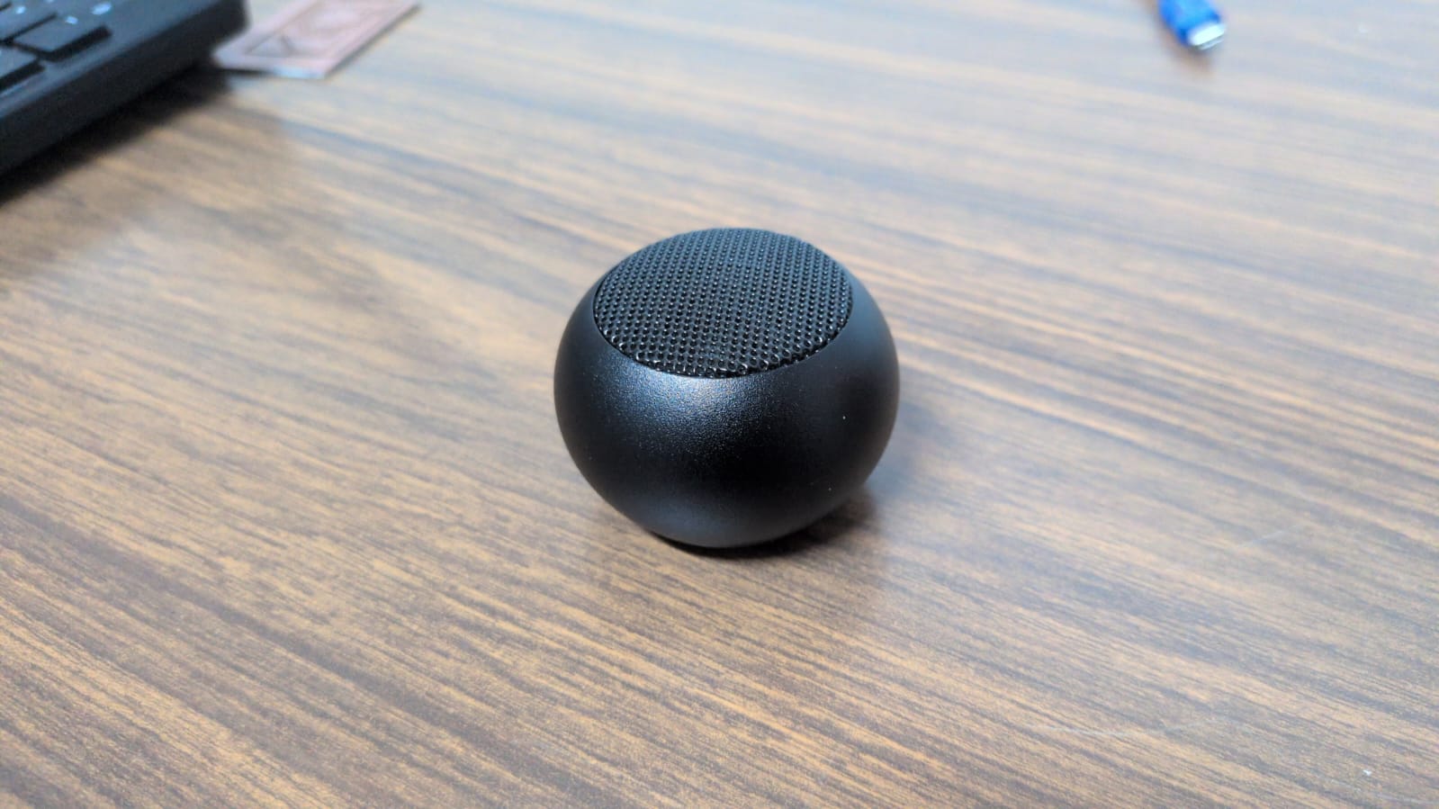
The Solution
I managed to find a cheap and small Bluetooth speaker online. This speaker has extremely good audio quality for its size. This was a concern, as usually smaller speakers sacrifice audio quality for size. This one worked perfectly, its almost as if it was designed for projects like this. Connecting the speaker to the Raspberry Pi 5 was also really easy. The Raspberry Pi OS’ desktop environment includes controls for audio levels and Bluetooth connections. We just need to start the speaker on pairing mode, by pressing the On button until we get a light + audio feedback. Then, we connect to the appearing device in our Bluetooth panel. Once paired, we need to make sure that our speaker is selected as the audio output device, by navigating once again to the Bluetooth panel, selecting our device and clicking the “connect” button. Now, we can test our speaker using something like YouTube.
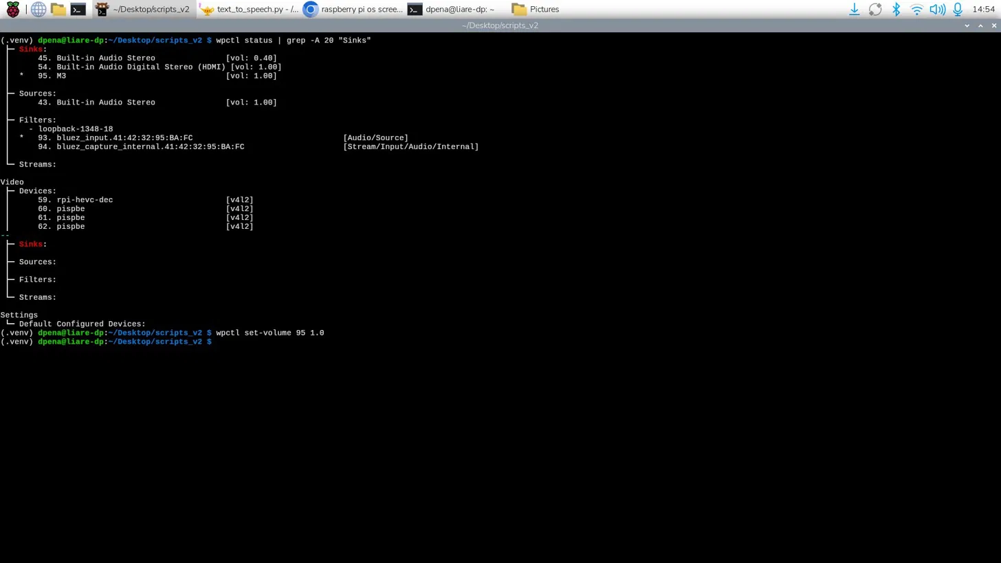
The first thing I noticed was that the volume was quite low. My system had already max volume levels, so I needed to modify the device’s audio levels. For that, I just had to run the following commands, the first one being: wpctl status | grep -A 20 "Sinks". In this command, “wpctl” being WirePlumber’s control command. WirePlumber is a wrapper around PipeWire, a sound and video Linux framework. WirePlumber manages audio devices on your Linux device. Here we are getting the status of the service. The “|” is a “Bash pipe”, Bash being the scripting language for the terminal. This character states that any output from the previous command (wpctl status) will be passed as the argument of the following command: grep -A 20 "Sinks". The “grep” command finds text strings inside its text input. With this second command, we are finding the “Sinks” section of the wpctl status command and listing them. Now we need to find the number of sink corresponding to our device, in my case it was 87. Finally, we can run wpctl set-volume 95 1.0 to set the volume of sink 95 (our speaker) to 1.0, or 100%. We can boost this volume level even further, by passing 1.5 as an argument, leaving us with a 150% volume. This is not recommended as higher volume outputs than the prebuilt “100%” can harm the speaker. Only change the volume level to something higher than 100% if the volume is just not enough.
Now, we can run our main.py script to test that our AI’s answers are being spoken correctly. The first initial run didn’t worked properly, there was no audio output. This was because we where telling our text to speech script to use our device’s default audio output device, which was none. So, by telling our script to use our speaker as the audio output device, the text to speech system finally worked properly! However, there is still a little issue to correct. There seems to be a little pause when starting to “read out loud” each chunk of text passed to the text to speech. This might be an issue of WirePlumber failing to load on time. I’m still researching how to solve this problem, maybe adding a small delay before starting the text to speech output might help. Until then, we can safely say that the programming part of the robot is done! There are still some issues to be solved, like the Xiao Sense camera issues I’ve been having.
May 25th
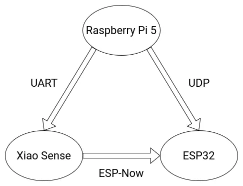
Communications
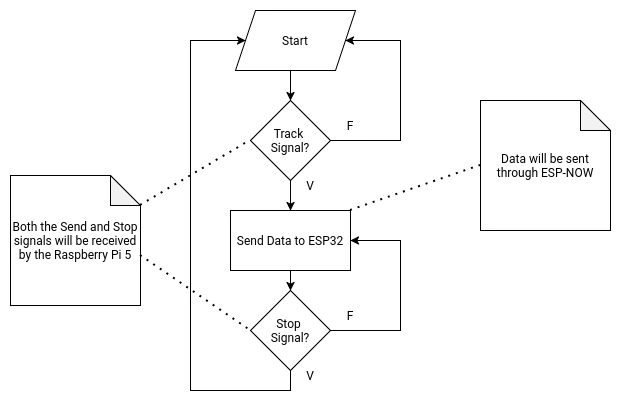
The following diagram details the final communication protocols used for the various micro-controllers involved on the Robot.
May 3th
ESP-Now
ESP-Now is a wireless communication protocol developed by Espressif, specially for the ESP32 and ESP8266 chips. ESP-Now works without a WiFi connection, in a quick low-power way. ESP-Now is the ideal wireless communication protocol for the ESP32 chip, and both our Xiao Sense and Xiao ESP32s3 micro-controllers are based on said chip. ESP-Now allows a max payload of 250 bytes, so sending int values (the coordinates generated by the person tracking) can be done without an issue. Plus, the quick nature of ESP-Now can (hopefully) give us near real time data transfer.
Implementing ESP-Now is also quite easy. We will be working with a “Sender” and “Receiver” code. For the “Sender” script:
        import network
        import espnow
        import time
        import machine

        # WiFi Configuration
        sta = network.WLAN(network.STA_IF)
        sta.active(True)
        sta.disconnect()

        # ESP-Now initialization
        e = espnow.ESPNow()
        e.active(True)

        peer = b'\xXX\xXX\xXX\xXX\xXX\xXX'
        e.add_peer(peer)

        # Example Sensor for Data Collection
        sensor = machine.ADC(machine.Pin(1))

        while True:
            val = str(sensor.read())
            e.send(peer, val)
            time.sleep_ms(10)
First of all, we need to install and import the “espnow” library. We can do this by running pip instal espnow in our virtual environment. Then, we configure the WiFi of the ESP32s3. ESP-Now does not use WiFi, but it requires the MAC address of the micro-controller. Then, we start the ESP-Now protocol and write the MAC address of the receiver into the “peer” variable. Finally, we use the e.send(peer, data) function, with the “peer” argument being that peer variable from above, and the “data” argument being whatever we want to send to the receiver.
To get the MAC address of your receiver for your “peer” variable, run the following script in your receiver micro-controller:
        import network
        print(network.WLAN(network.STA_IF).config('mac'))
For the “Receiver” script:
        import network
        import espnow

        sta = network.WLAN(network.STA_IF)
        sta.active(True)
        sta.disconnect()

        e = espnow.ESPNow()
        e.active(True)

        print("Waiting...")

        while True:
            host, msg = e.recv()
            if msg:
                print(f"From: {host}, Message: {msg}")
Here we start the WiFi and the ESP-Now protocol like with the previous script. Then, with the e.recv() function we receive the “host” and “msg” variables. These variables tell us where the message is coming from and what that message is.
With a couple of lines, we are basically ready to use ESP-Now as we need it in our final scripts. For more information of everything you can do with ESP-Now in Micropython, check out the Micropython’s Official Documentation on ESP-Now.
For Arduino, the idea stays the same, just with a couple more lines of code. For the “Sender”:
        #include <esp_now.h>
        #include <WiFi.h>

        // Receiver MAC Adress
        uint8_t broadcastAddress[] = {0xXX, 0xXX, 0xXX, 0xXX, 0xXX, 0xXX};

        typedef struct struct_message {
          int valor;
        } struct_message;

        struct_message myData;
        esp_now_peer_info_t peerInfo;

        void setup() {
          Serial.begin(115200);
          WiFi.mode(WIFI_STA);

          if (esp_now_init() != ESP_OK) return;

          memcpy(peerInfo.peer_addr, broadcastAddress, 6);
          peerInfo.channel = 0;
          peerInfo.encrypt = false;

          if (esp_now_add_peer(&peerInfo) != ESP_OK) return;
        }

        void loop() {
          myData.valor = analogRead(A0); // Example Sensore Data
          esp_now_send(broadcastAddress, (uint8_t *) &myData, sizeof(myData));
          delay(10);
        }
And for the “Receiver”:
        #include <esp_now.h>
        #include <WiFi.h>

        typedef struct struct_message {
          int valor;
        } struct_message;

        struct_message myData;

        void OnDataRecv(const uint8_t * mac, const uint8_t *incomingData, int len) {
          memcpy(&myData, incomingData, sizeof(myData));
          Serial.print("Dato recibido: ");
          Serial.println(myData.valor);
        }

        void setup() {
          Serial.begin(115200);
          WiFi.mode(WIFI_STA);
          if (esp_now_init() != ESP_OK) return;
          esp_now_register_recv_cb(OnDataRecv);
        }

        void loop() {}
The idea is to use Micropython/Python in every script, as to maintain a level of consistency in our project. Mixing Mircopython and Arduino in the same project is posible, and ideal when a part of the project requires faster execution speeds, but if we can keep everything in the same language, we should.
If, at any moment during the rest of this projects development, Micropython stops “cutting it”, Arduino will step in as the main language (except for anything AI related).
May 10th
As of the time of writing this, ESP-Now is no longer needed for this project, as the Xiao Sense will no longer be in charged of transmitting data to the ESP32. For more information on this change, please refer to the Person Tracking section of this page. This ESP-Now section will remain up on this page, as to have a secondary wireless protocol for backup and as reference and guiding for future projects.
UART (Serial)
For serial communication, I decided that the serial worker given to us by our local instructor Rafa for our week 14 assignment was more that enough for our application. We are basically sending an “On” and “Off” signal from the Raspberry Pi 5, which the Xiao Sense will read and act upon.
For this, I added the Serial Worker script to my Raspberry Pi code base. I added the “On” send function underneath the wake up word detection on the main script:
Once the Xiao Sense script is up and running, the receive function of the Serial Worker must be added with the needed logic in order to start the tracking.
May 9th
UDP
For our project, the Raspberry Pi 5 and the Xiao ESP32s3 on the motor casing need to communicate in a wireless, real time way. ESP-Now would be the best option if we where working with both ESP32 chips. But the Raspberry Pi 5 has no ESP32, therefore it does not support ESP-Now. Luckily for us, there is a second wireless, real time communication protocol we can use.
“User Datagram Protocol”, or UDP, is a core communication protocol of the internet. UDP was created to send messages to other hosts on an Internet Protocol network, more specifically Web Sockets. Web Sockets creates a bidirectional communication channel using the TCP protocol (Transmission Control Protocol). Web Sockets update on real time, therefore creating real time communication.
Using UDP in Micropython is quite easy. First of all, we need to install the “socker” library running pip install socket in our virtual environment. We’ll be having “Sender” and “Receiver” scripts, as well as a couple lines of code that both scripts will be needing. These couple lines of code are:
        import network
        import socket
        import time

        def connect(ssid, password):
            sta_if = network.WLAN(network.STA_IF)
            sta_if.active(True)
            if not sta_if.isconnected():
                print('Connecting to WiFi...')
                sta_if.connect(ssid, password)
                while not sta_if.isconnected():
                    pass
            print('Network Config:', sta_if.ifconfig())
            return sta_if.ifconfig()[0] # Returns local IP address
This function will help us connect both the receiver and sender to a local WiFi network. Then, the “Sender” script will look like this:
        import socket
        import time
        import machine

        # Configuration
        SSID = "<your_WiFi_name>"
        PASSWORD = "<your_Password>"
        IP_RECEPTOR = "192.168.1.XX" # Change for the IP address printed by connect()
        PORT = 5005

        # Connect to WiFi
        connect(SSID, PASSWORD)

        # Create a UDP Socket
        sock = socket.socket(socket.AF_INET, socket.SOCK_DGRAM)

        adc = machine.ADC(machine.Pin(1)) # Example sensor

        while True:
            message = str(adc.read())

            # Send data
            sock.sendto(message.encode(), (IP_RECEPTOR, PORT))

            print(f"Sending: {message}")
            time.sleep_ms(20) # Real time sending frequency
In this code, we create a variable for both our WiFi’s name and password. We then run the previous connect() function to connect to said WiFi network. Then, we create the socket, from which we will be sending and receiving data. Finally, with the sock.sendto(messaje.enconde(), (IP_RECEPTOR, PORT)) function, we send the data. This data will be an encoded string, meaning that our proposed “Move” and “Stop” string signals are valid.
For the “Receiver”:
        import socket

        # Configuration
        SSID = "Tu_Nombre_WiFi"
        PASSWORD = "Tu_Password"
        PORT = 5005

        # Connect to WiFi
        connect(SSID, PASSWORD)

        # Create UDP Socket
        sock = socket.socket(socket.AF_INET, socket.SOCK_DGRAM)
        sock.bind(('0.0.0.0', PORT))

        print(f"Waiting for data on Port {PUERTO}...")

        while True:
            data, addr = sock.recvfrom(1024)
            print(f"Received: {data.decode()} from {addr}")
The first parts stay the same, we declare our network’s variables, connect to WiFi and create the UDP Socket. The Socket will then hear every interface from the selected port (must be the same port declared on the sender script). Finally, in our main loop, we grab any incoming data and save it into the script (or for this example, printing it).
Note: This communication protocol was meant to be used with the sound detection system of the project. As of the time of writing this, the sound detection system is in a lesser priority on the Project Goals. For more information on why implementing sound detection will be a challenge and why this decision was made, please refer to the DOA Algorithm section of this page. The investigation and script development for UDP communication will still be here in case time favors us and the sound detection system can be implemented.
May 10th
As of the time of writing this, UDP has returned to be a main communication protocol, between the Raspberry Pi 5 and the ESP32 in the base of the robot. For more information on why this change was applied, please refer to the Person Tracking section of this page. The code from above works perfectly fine for the receiver, but the sender needs some modifications. Essentially, the example code from above works with micro-controllers (micropython). The Raspberry Pi 5 needs its own not-micropython code. The idea stays the same, just without the "network" library (which only works with micropython). I ended up writing a worker that handles everything by itself:
        import socket
        import time

        class UdpWorker:
        	def __init__(self) -> None:
        		self.PORT = 5005
        		self.IP_RECEPTOR = "192.168.0.119"

        		self.sock = socket.socket(socket.AF_INET, socket.SOCK_DGRAM)
        		print(f"Socket ready, sending to {self.IP_RECEPTOR}:{self.PORT}")

        	def send(self, val):
        		try:
        			message = str(val)
        			self.sock.sendto(message.encode('utf-8'), (self.IP_RECEPTOR, self.PORT))
        			time.sleep(0.02)
        		except Exception as e:
        			print(f"Error al enviar: {e}")

        # Use Case
        if __name__ == "__main__":
        	worker = UdpWorker()
        	worker.send("Hello, world!")
        	print("Message sent Correctly!")
As you can see, the idea stays the same. Instead of handling the WiFi connection directly from the micro-controller, this new script uses the OS to handle that, that’s why there is no SSID and password declaration, the system already knows that.
The good thing about this script is that it can send to both Micropython and Arduino receivers, meaning that we now have complete freedom on what language to use for the ESP32. As the script I used for the example at the end of my Week 14 page was written in Micropython, I might stay with it as a base. The only things to add to that script are the UDP receiver logic and the ratio contemplation of the stepper motor.
Mechanics
360 Rotating Base
The main aspect of the final project is it’s ability to rotate 360 degrees, enabling the sound detection -> person tracking functionalities of the robo-agent. For this rotary base to work properly, we need a couple of components:
- A stepper motor.
- An electrical slip ring. (SCRAPPED)
- A 3D printed base with a gear system.
For this rotating base, a gear based system seems optimal, as to allow a single motor to deliver the torque needed to move the whole robot. As I don’t currently know the weight of the final robot, the gear based system needs to have enough torque to move it, plus having the precision to face the robot to an exact angle. For torque and precision applications, a planetary gear arrangement is optimal.
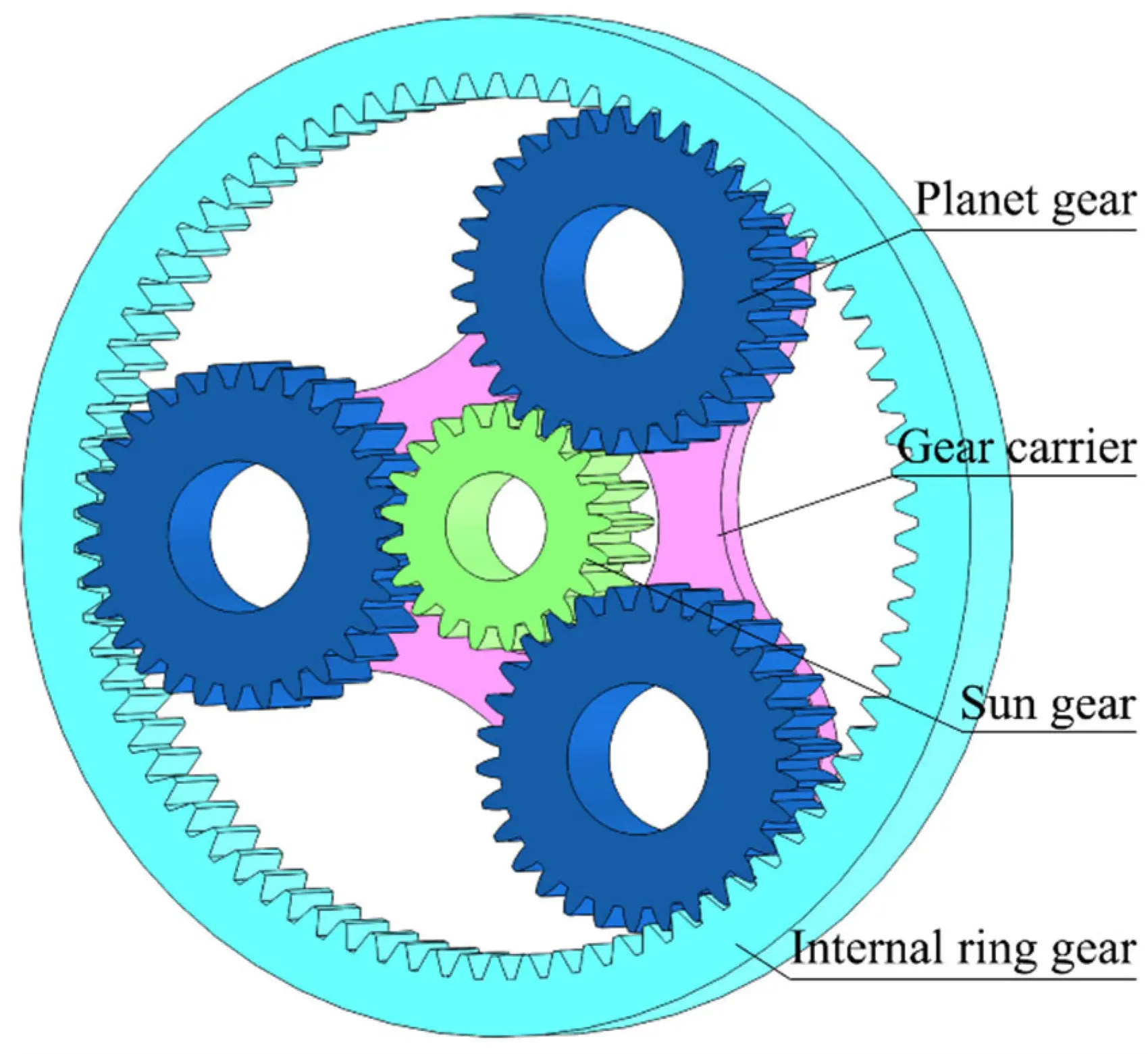
For a better explanation on how planetary gears work, and how to make them, check out this YouTube video by the 3D Printer Academy channel. The idea is to design a similar planetary gear from scratch, with a 5:1 movement ratio (standard for robotics applications). A NEMA stepper motor will be placed underneath the sun gear for the base movement. Plus, ball bearings are proposed for the inside of each planet gear, for a smoother rotation of the gear carrier. The base where the robot will be placed will also be attached to the top of the gear carrier.
Note: The original idea included the use of an electrical slip ring at the core of the rotating base. This slip ring would have allowed for power sharing between the base of the robot and the robot itself. However, powering everything through the slip ring would have caused problems, mainly with the Raspberry Pi 5 powering. In the spirit of compartmentalization and separating the rotating base from the robot, the slip ring idea was scrapped, opting for having separate power supplies for the base (12v 5a power supply) and the robot (the Raspberry Pi 5’s dedicated power supply).
Getting more into electronics, the stepper motor will be wired into a drv8825 driver, which will then be controlled by the ESP32. This driver is more than enough to allow for my motor to work. In the programming department, the stepper motor can use a similar script to the one I developed for my week 14 assignment, with a few modifications, including adding the UDP communication logic, the sound detection and the 5:1 ratio implementation.
Designing The Planetary Gear
I will be using OpenSCAD for all my final project’s CAD design, as I feel the most confortable with it. The OpenSCAD community, driven by user Belfry on GitHub, developed the BOSL2 Library (Belfry OpenSCAD Library). This library includes a lot of useful pieces and functions that vanilla OpenSCAD does not include, and that simplify the designing process.
BOSL2 includes a dedicated gear library, allowing us to easily configure our gears in a parametric way. The BOSL2 documentation pagesection on spur gears include an example of a planetary gear system, which I based my first design of. BOSL2 does include a planetary gear function to instantly create planetary gear systems. Although really useful, I decided not to use this function, as building every gear from scratch would give me more control over the final model.
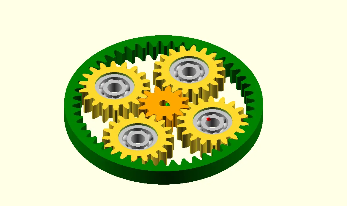
This is the proposed system. As you can see, there are 4 plant gears, each of them contemplating a ball bearing on its core. The sun gear and planet gear sizes are also configured to have that 5:1 ratio we talked about. In theory, this planetary gear should move perfectly, but its missing some key details:
- Its missing the planet gear carrier.
- Its missing the bottom casing for the stepper motor.
- Its not contemplating the stepper motor on its core.
Adding everything else was quite straight forward. For the base, I extended the shape of the outer ring, plus adding a floor to hold the carrier. For the carrier, I created a disk with cylinders the shape of the inter radius of the ball bearings. And in the end, using the difference() function, I extracted the shape of the stepper motor from the whole model, creating the necessary space to hold the motor and its shaft. The first draft of my planetary gear system ended up looking up like this:
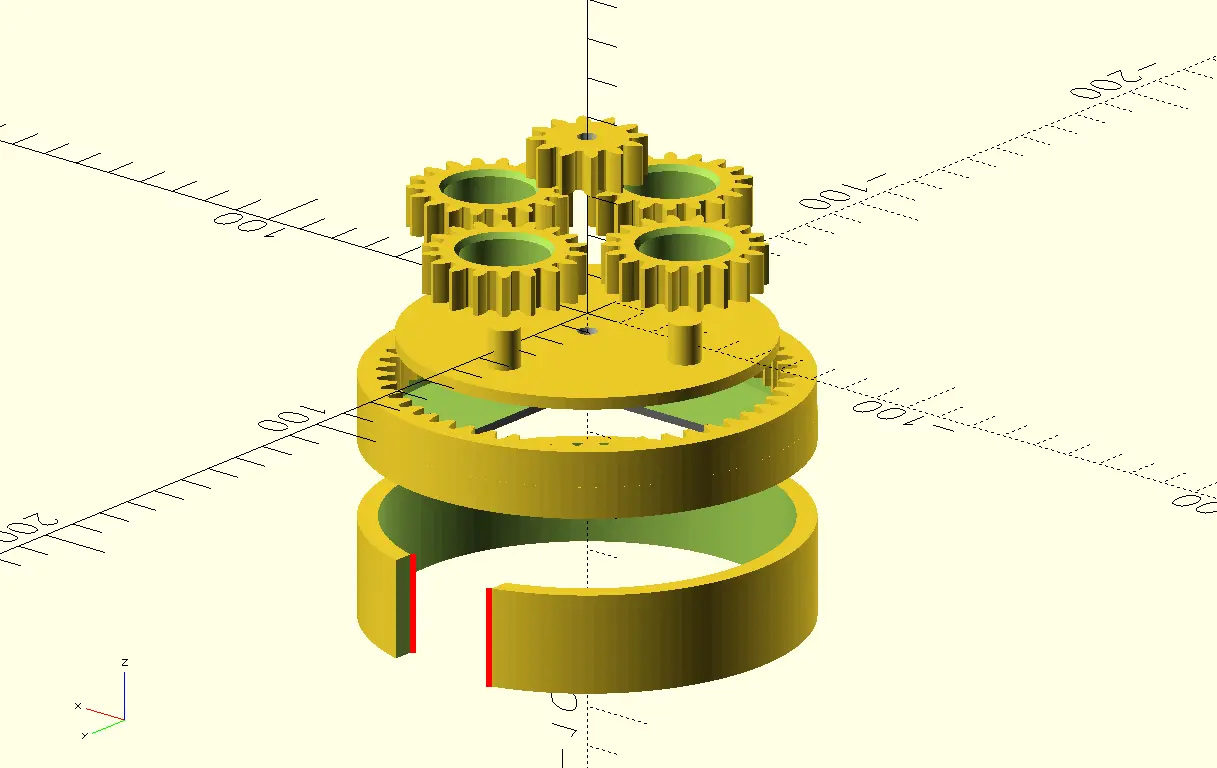
From top to bottom we can see:
- The stepper motor casing part of the base (this will be attached to the outer ring part).
- The outer ring and its floor extension.
- The carrier.
- The planet gears.
- The sun gear.
The diameter of the base ended up being of 11cm. This might sound small, but in reality is more than enough to hold the robot, as the Raspberry Pi 5 is quite small, approximately 8.5cm wide. Plus, there is no problem if the robot exceeds the size of the base.
The next step will be printing the base and testing it on its own and with the stepper motor.
May 6th
At the time of writing this, I’m still not done printing the first draft of pieces, even though I’ve tried to all this time. I was planning on printing everything at once in our Prusa XL machine. The problem with the Prusa XL is that it is the most demanded 3D printer in our university, so it is always busy. After a couple of days waiting for my opportunity to use the printer, I decided I was "wasting my time", and decided to start printing in the Ender 3 S1 Pro I repaired during my [week 3 work]() (the one on Rafa’s Cave). We where already having some issues with this printer, particularly with "Spaghetti Failure", a common printing fail which symptom is long, messy strings of filament ruining the print.
My first couple of attempts at printing my gears where all fails because of this. I tried running the self leveling function of the printer several times, one of which did work and allowed me to print the first planet gears, one by one. Looking back, not printing everything at once in the Prusa XL saved me from a big disappointing, as I my ball bearings did not fit this first planet gear. I forgot to compensate for the printing’s extra material added, I designed considering the "theoretical" space needed. Adding some spacing made the following 4 planet gears to come perfectly.
The next one was the sun gear, which I also forgot to add spacing. After the second attempt the gear fitted perfectly into my stepper motor’s shaft. With the carrier piece, though, I had problems. The carrier piece is a big disk with some pillars. My printer kept messing up halfway though the disk part of the print, sometimes not even reaching halfway. Here’s where I decided I needed to do a complete manual calibration of the printer. Not only did I used the "paper method" of placing a sheet of paper underneath the extruder and moving it around whilst lowering the extruder until the paper moves no more, which means the extruder is now level with the bed of the printer. Then, I moved the extruder into the 4 corners of the bed, and realized the bed also needed some leveling in some corners. Using the manual gear on each corner of the bed, I adjusted them so that the paper moved the exact amount on each one. This way, the carrier piece was able to be printed.
The next one was the sun gear, which I also forgot to add spacing. After the second attempt the gear fitted perfectly into my stepper motor’s shaft. With the carrier piece, though, I had problems. The carrier piece is a big disk with some pillars. My printer kept messing up halfway though the disk part of the print, sometimes not even reaching halfway. Here’s where I decided I needed to do a complete manual calibration of the printer. Not only did I used the “paper method” of placing a sheet of paper underneath the extruder and moving it around whilst lowering the extruder until the paper moves no more, which means the extruder is now level with the bed of the printer. Then, I moved the extruder into the 4 corners of the bed, and realized the bed also needed some leveling in some corners. Using the manual gear on each corner of the bed, I adjusted them so that the paper moved the exact amount on each one. This way, the carrier piece was able to be printed.
May 12th
At the time of writing this, all of the planetary gear system prints are ready to go. It took some time and several trial and error prints to get to this point. Over all, every piece was printed the following times until reaching the last iteration:
- Planet gear - 3 iterations.
- Sun gear - 2 iterations.
- Carrier - 2 iterations + several print failures.
- Base - 2 iterations + several print failures.
The amount of 3D printing needed for this project is slowly coming out as the biggest bottle neck in the development.
Still, the rotating base is ready to be assembled and tested upon. Assembling is quite easy. I just needed to insert the ball bearings inside the planet gears and insert those in the carrier. The carrier then sits inside the rotating base, and where done. The stepper motor was also placed, coming from underneath the base and attaching its shaft to the sun gear. The first test I ran with the rotating base was a simple one way rotation script. The rotating base moved as expected. Some “rattling” noise was present, but that was to be expected.
The thing I could note from this initial test is that the base moves itself whilst operating. This will not be a problem, as the weight of the robot will pin the base further down to our floor. Plus, the rotating base function is to adjust its position in small intervals, not perpetual high-speed movement. As a hole, the planetary gear system works perfectly well. It is now ready to connect with its PCB and start testing the tracking movement.
May 21th
The Body
For my week 2 assignment I designed the first prototype of the two main components of our robot’s casing: The Body and The Tentacles. My plan was to use these designs as a starting point for this final design. Again, all of my CAD design will be done in OpenSCAD. I found out that FreeCAD has a dedicated OpenSCAD “workbench” to mix SCAD and regular CAD design processes. I couldn’t achieve this as there seems to be some issues with my OpenSCAD installation method (Linux) and the requirements for FreeCAD to detect OpenSCAD in the system. I’ll keep on trying to get this workbench going, as it seems to be my “sweet spot”.
Starting with the body, the original sketch involved a “pealed” like design, of 6 different sections of a sphere that would be placed together to form the final shape. I really don’t know why I designed it this way, but doing it like so would have make the whole process harder. So I decided to ditch this original design and create a new one from scratch. Now, the idea was to design a casing that would connect directly into the the rotating base, having everything secured inside, including the eye screens, Raspberry Pi 5, Xiao Sense, etc.
Before starting this design though, I designed a replica of the oled screens I was going to use for the eyes of the robot. This model would help me design some eye holes in the round shape. I took measurements of the real oled screen and starting designing.
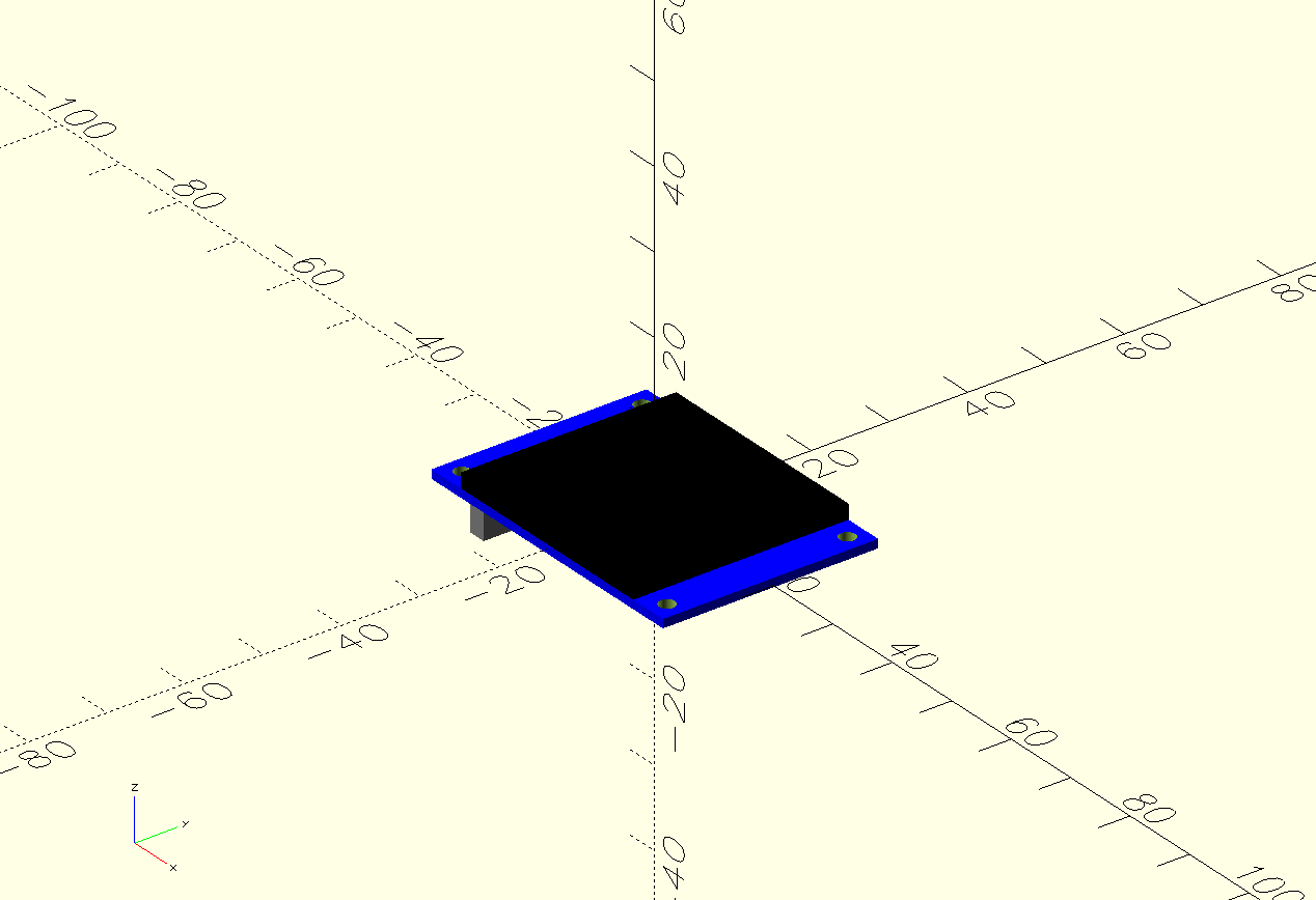
Now, I used this screen to remove some sections of the new casing to create its holes:
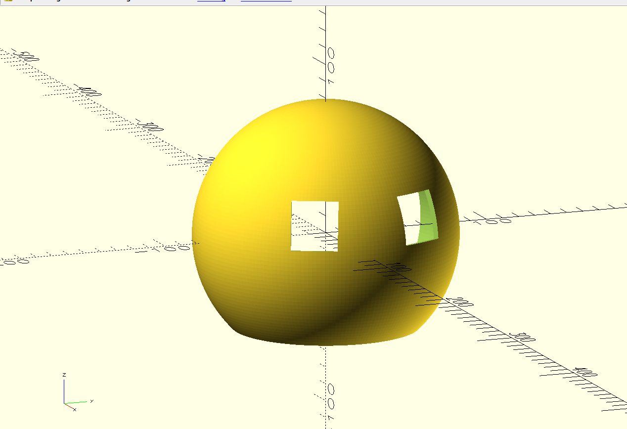
Here’s where development stopped for a while, as this is when I decided to test the oled screens, and had no luck with them. For more information on this testing, check out the Eye Screens section on the Electronics part of this page. This part of the page explains why I decided to scrap the idea of eye screens, meaning that these screen holes where no longer necessary. The silver lining of this decision is that the body design is now easier for me.
With the eye sockets removed, I designed some holes for the tentacles. I went with 6 holes in total. This holes will need to support the tentacles somehow, I still had no idea on how. Regardless, I printed this first iteration of the main casing for testing purposes. This testing gave me some positions for the microphone and the Xiao Sense camera.
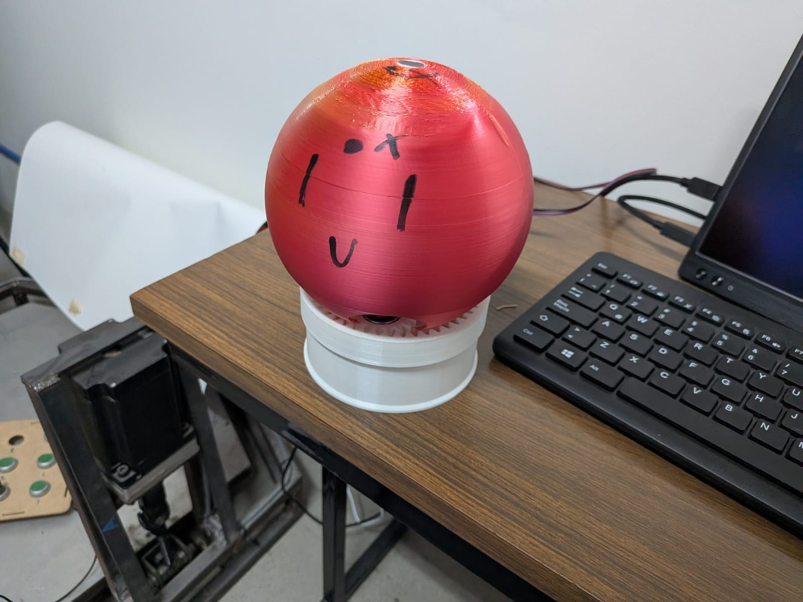
I then returned to OpenSCAD and created those needed holes. Plus, I used an available .stl model for a Xiao ESP32S3 casing to fix the camera inside the body in its right position. You can find this model on the Seeed Studio Getting Started page for the ESP32S3. The following drawing showcases the preliminar sketch of the component placement inside the casing:
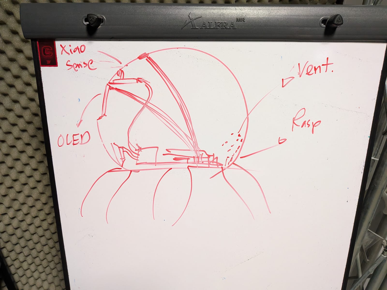
The 3D design followed the same pattern:
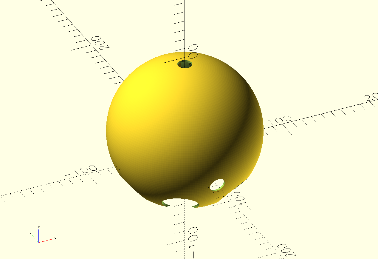
There are in total 3 holes: A microphone hole at the top of the casing, a camera hole at its front and a charging hole on its back. The camera casing is not visible on this shot, but is there. I proceded to print this new model for further testing.
There is one last thing I designed: the base that will connect the rotating base and the casing. This base included two types of perforations: 4 cylindrical perforations to connect to the carrier of the planetary gear system, and 6 connections for the extruding part of the casing left behind from the tentacle perforations.
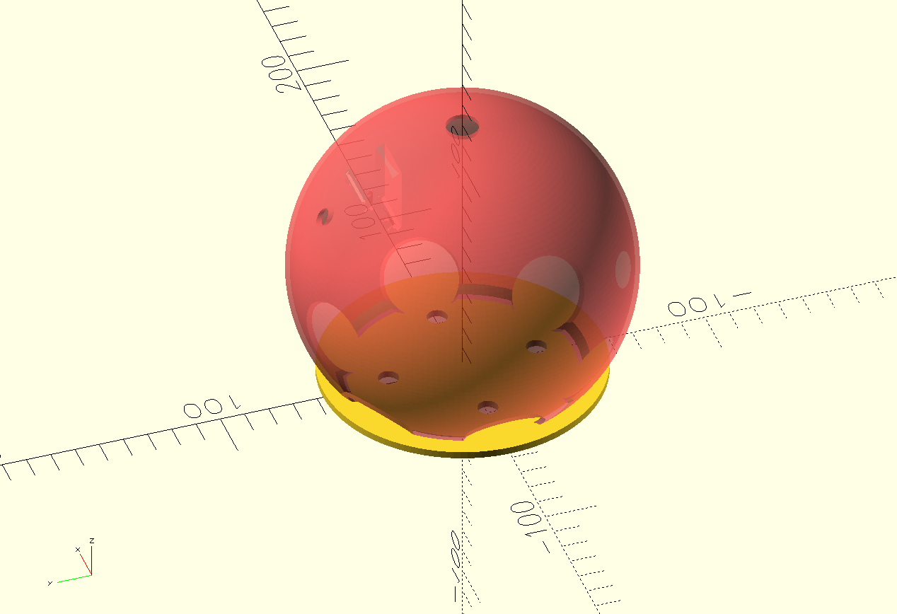
The red part is not a part of the model, and its just there to exemplify how those grooves where made for the casing to connect. This solution meant that I needed to redo my carrier for the planet gear system, extending the 4 pillars for the planet gears even further up.
May 23th
The Tentacles
For the tentacles of the robot, the design created for my week 2 assignment work perfectly fine. There where two problems I needed to solve, though:
- How to connect the tentacles to the casing?
- How to add some movement to the tentacles?
Starting with the second problem, I needed to think of a way to give motion to the tentacles. Whilst planning this project, I thought that the movement from the base itself could make articulated tentacles to have movement. I realized, thought, that my current version of the base only moves in small intervals, reducing the movement the tentacles could possibly have. A new solution will be needed. This new solution would need to give the tentacles up and down movement preferably (adhering to the original servo motor powered tentacles proposed at the beginning of the year), or some other kind of movement that could give life-like motion to the octopus.
I first thought of a “wave” border on the rotating base. This wave border would theoretically make the tentacles up and down as they moved around. This means that the tentacles would need some sort of fixing to the casing that would allow up and down movement, most likely a horizontal rod across the base of the tentacle. This solution seemed plausibly, but would require a lot of testing to ensure that the wave border would hinder the movement of the base.
My instructor suggested two solutions: a pulley solution or a gear solution. The pulley solution involved passing a string through the tentacle, from tip to base. This string would be attached to “somewhere” that, when moved, would retract the string causing the tentacles to contract and move. The gear solution involved using gears in the base of the tentacle and adding gear teeth to the rotating base. When the robot moves, the tentacles will rotate following the gear’s movement thanks to the gear teeth on the base.
My instructor’s suggestions where useful, but too complicated for my current skill and remaining time. I thought this movement options where too “over engineered” for this initial project. I wanted a simple solution that could give some movement to my tentacle’s. Then I had an idea: I took inspiration from Mexican culture, more specifically from a cute craft your can find with some Artisans:

These turtle “alebriges” have a free moving head. If you touch it, the head will move up and down until stopping. The science behind this movement is really simple. The head is attached with a string to the top of its shell, exactly on its balance point. This means that the head is always suspended in the air and, with some movement, the balance of the head will shift causing its movement. The movement only stops when the balance is restored.
Using this solution for my tentacles should accomplish the same thing. Achieving a perfect balance with my tentacle would be almost imposible, plus the idea is for the tentacles to rest on the floor. Still, suspending the tentacle in the air with some rope would cause the tentacle to be “unstable” and, with any kind of movement, the tentacle should move. This movement would be as noticeable as with the other proposed solutions, but it should be subtle enough to be both a clever and a valid solution. Only testing will tell.
May 22th
Assembly and Testing
3D Printing
With all the final pieces’ designs ready, I started the printing process. The rotating base’s pieces stayed without reprinting as they already function correctly. I printed the tentacles and body of the octopus in the Prusa XL, as its size allowed me to print them all at the same time. After 14 hours of printing, the pieces came out perfectly.
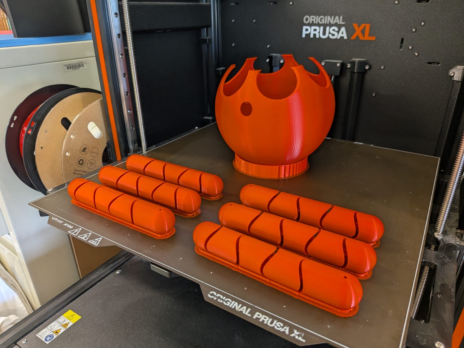
The rest of pieces remaining (the inner support for the Raspberry Pi 5 and the connector piece for the rotating base and the robot’s body) where printed in Rafa’s Cave Ender 3 s1 Pro.
Now, I had to prepare the tentacles. I got my hands on some red string that perfectly matched the tentacles color. With that, I fixed the tentacles to the insides of the robot’s head. The tentacles behaved as expected (please refer to the Tentacles section of this page for more information). The tentacles where suspended in the air, allowing for free movement without risk of disconnecting from the body. With that, the casing of the robot is ready!
Wiring
The only wires present on the inside of my project are the microphone wires. These wires where not in the way of anything else, so I just left them as they where. Other than that, I fixed the microphone head on its place. The only other connection inside the robot’s head is the Xiao Sense with the Raspberry Pi 5. For that, I soldered a custom USB to USB-C cable, with enough flexibility to allow a connection. This USB to USB-C cable serves only as a power cable, which means that I only needed to solder both the PWR and GND pads on each terminal. If my cable ever required to also function as a Serial communication method, I would only have to solder the remaining 2 pads on each terminal.
Assembling The Base
Here’s a render of how the pieces of my final project connect to one another:
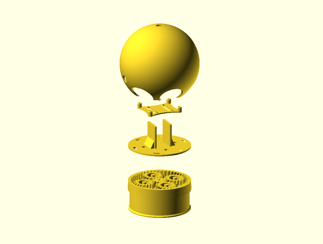
As you can see, the connection plate (the third piece from top to bottom) connects the main body with the rotating base. The Raspberry Pi 5 support (second piece from top to bottom) is attached to the connection plate, lifting the Raspberry Pi 5 to the center of the main body. The process of assembling my final project goes as follows:
- Prepare the rotating base:
- Place the stepper motor in its corresponding place inside the PCB.
- Place the base on top of the stepper motor and the PCB.
- Attach the gears to the stepper motor’s shaft.
- Connect the power cables to the block terminals on the PCB.
- Attach the connection base to the rotating base.
- Attach the Raspberry Pi 5 to its support piece and attach that to the connection base.
- Connect the microphone and the power supply cable (through its hole on the casing) to the Raspberry Pi 5.
- Place the main body on top, securing it to the rotating base.
After following all this steps, we will have our project completely assembled!
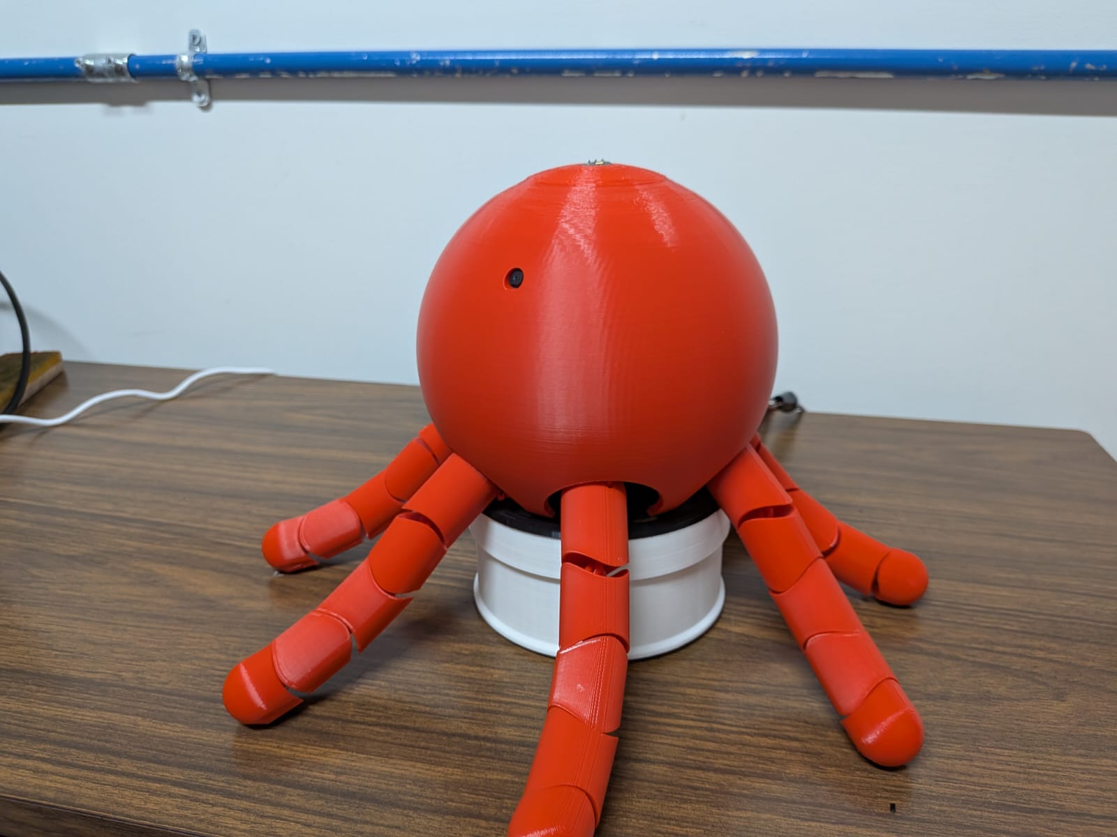
Vinyl Face
As explained on the Eye Screens section of this page, I had to scrap the proposed OLED screens for eyes on my project. As a result, I had to come up with a way to add a face to my project. And there is no better way that vinyl. With vinyl, I could easily design the face of my project, cut it out and paste it. As simple as it sounds, this step is crucial for giving my robot all its personality and charisma.
Firstly, I had to design the face. I started with some preliminary sketches of the face. My girlfriend studies animation, so she was kind enough to help me brain storm face ideas for my robot.
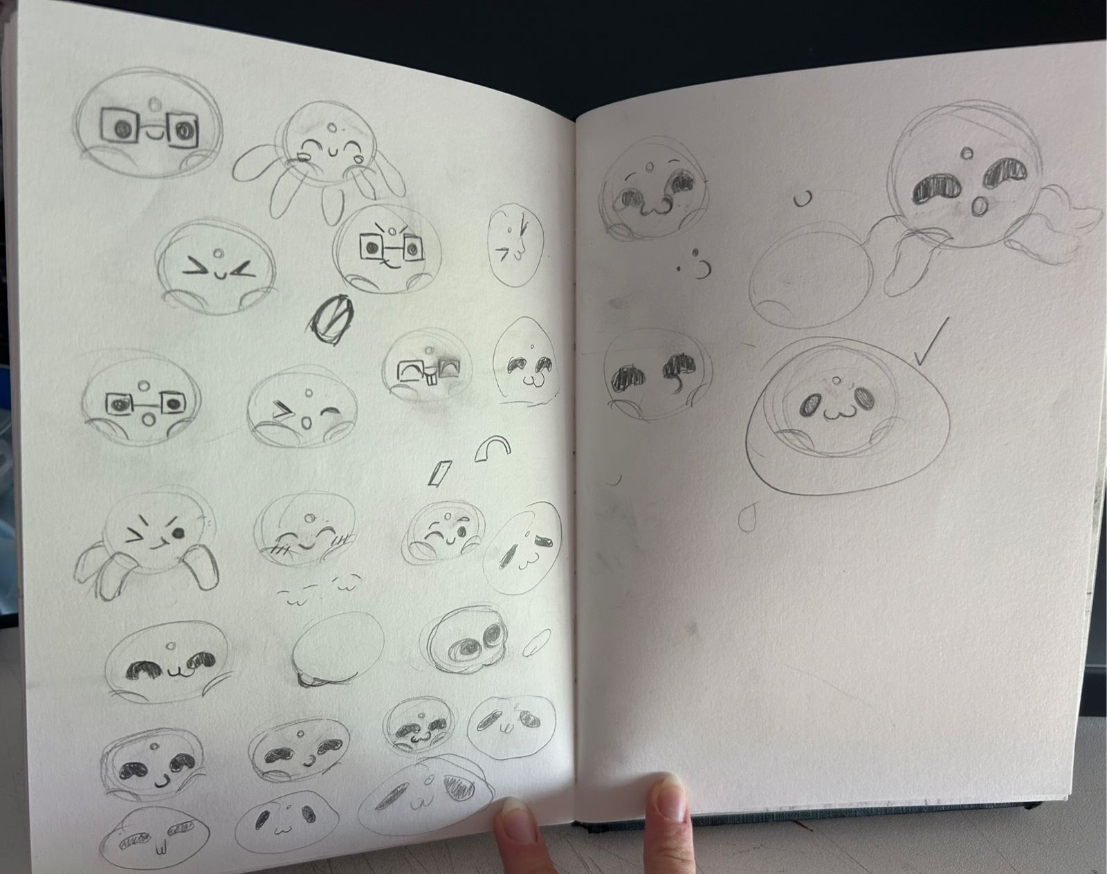
Once I selected a face that I liked, it was just a matter of bringing that sketch into a 2D vector program (in this case it was Adobe Illustrator) and vectorizing it. I initially wanted to follow my week 2 assignment page, repeating the process I used for that vinyl assignment. Unfortunately, the “drawn” aspect of that sketch prevented the automatic path tool from correctly matching the sketch. My girlfriend suggested replicating the sketch with the available tools of the program and, with a little bit of help from her, we ended up with an SVG image of the face.

Now, it was time to cut the face. Unlike in my week 3 assignment, this time I had to use a different machine. The process was still really similar, involving creating the toolpath for the image, setting up the machine, cutting and post processing the result.
I started up by loading up the program, CutStudio. I then loaded my image, now in a PNG format. Then, I needed to create the toolpath, by selecting the “create trace” option on the menu:
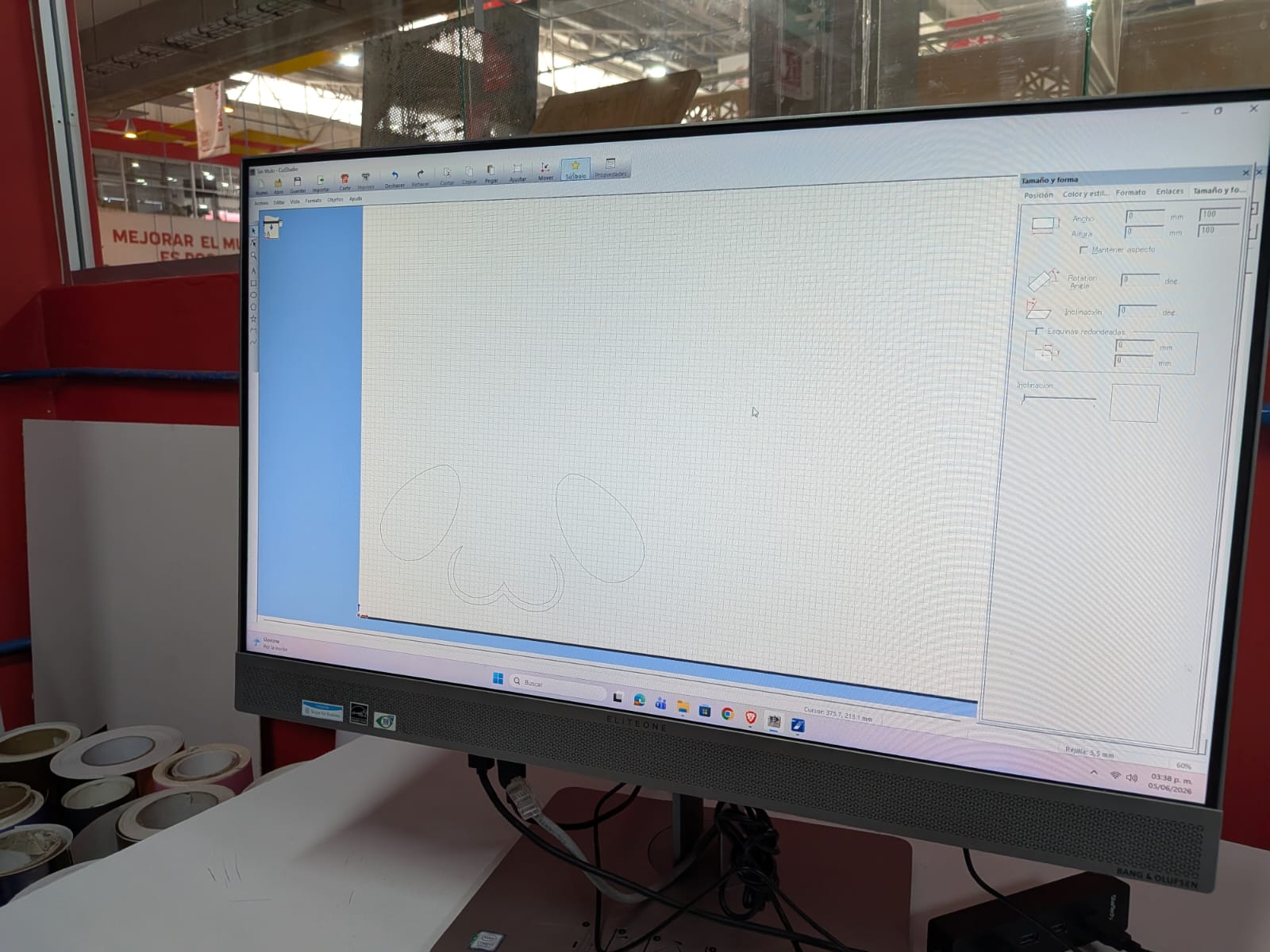
Now, we need to set up the machine. To do this, simple pass the vinyl through the machine and lock it in place. On the machine’s controls, click the “enter” button. The machine will automatically measure the length of your vinyl. Now, return to CutStudio and click the “Cut” option on the menu. Now, simply click “Ok”, and the machine will start cutting by itself.
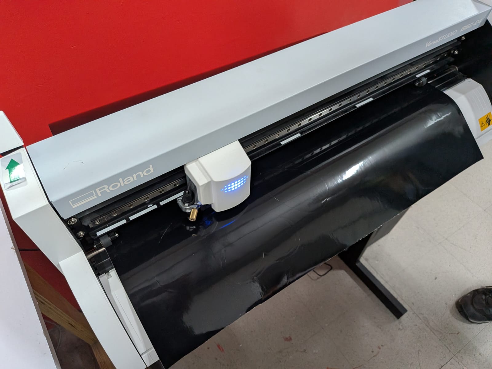
After that, we need to cut out the section of the vinyl we used and transfer it to a transfer paper sheet, just like I explain on my week 3 assignment page under the vinyl section.
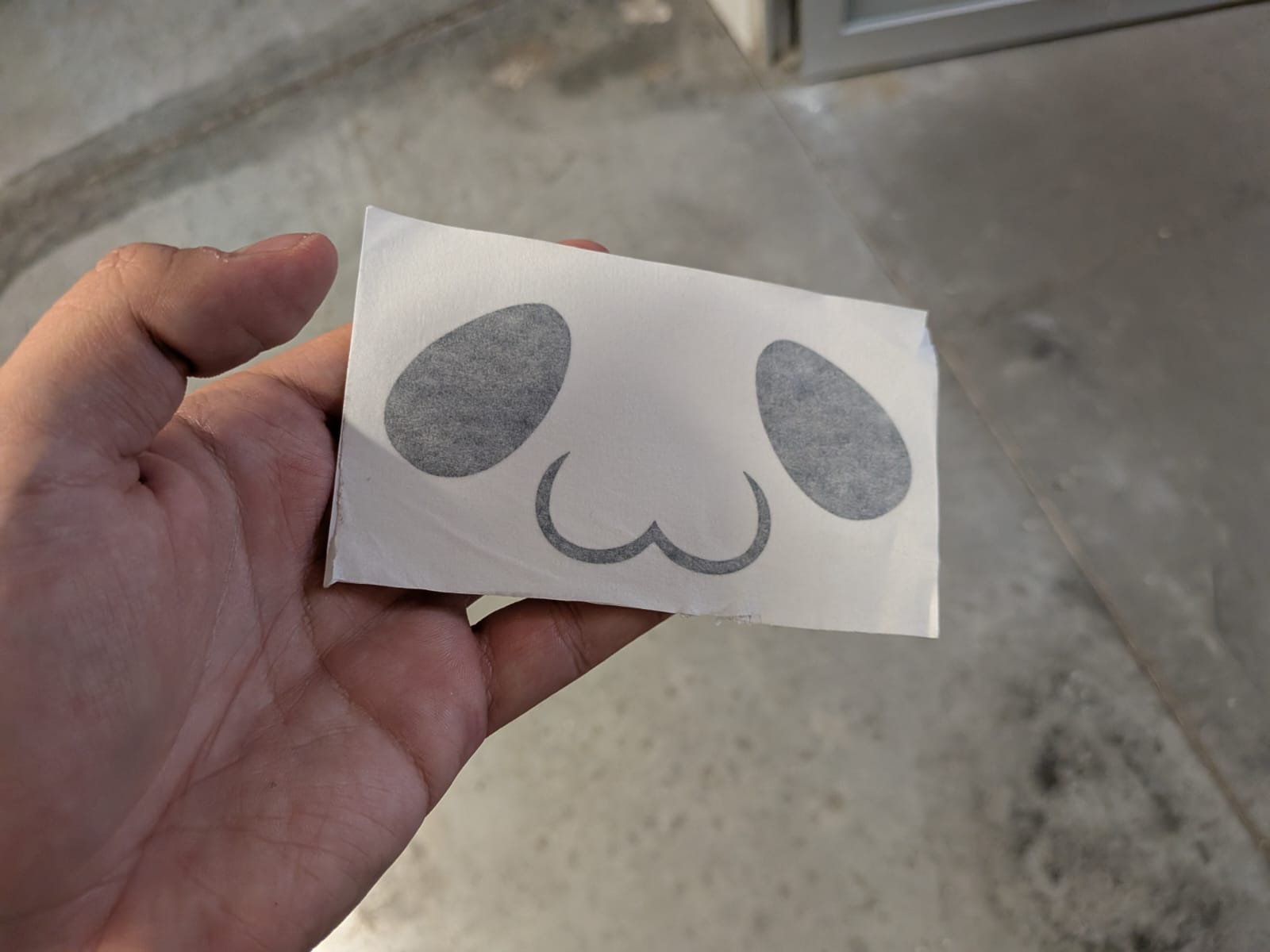
After that, we just need to paste it into our robot’s casing:
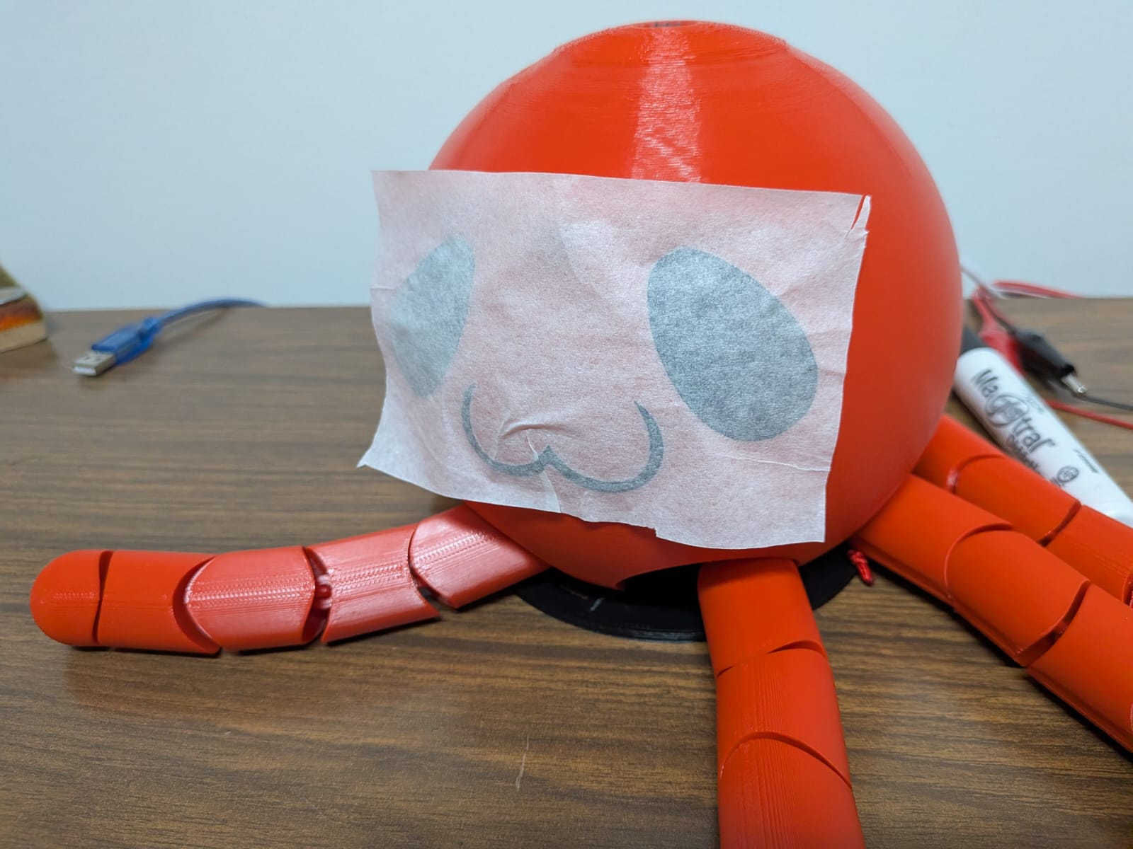
And after carefully applying and removing the transfer paper, the vinyl face is ready!
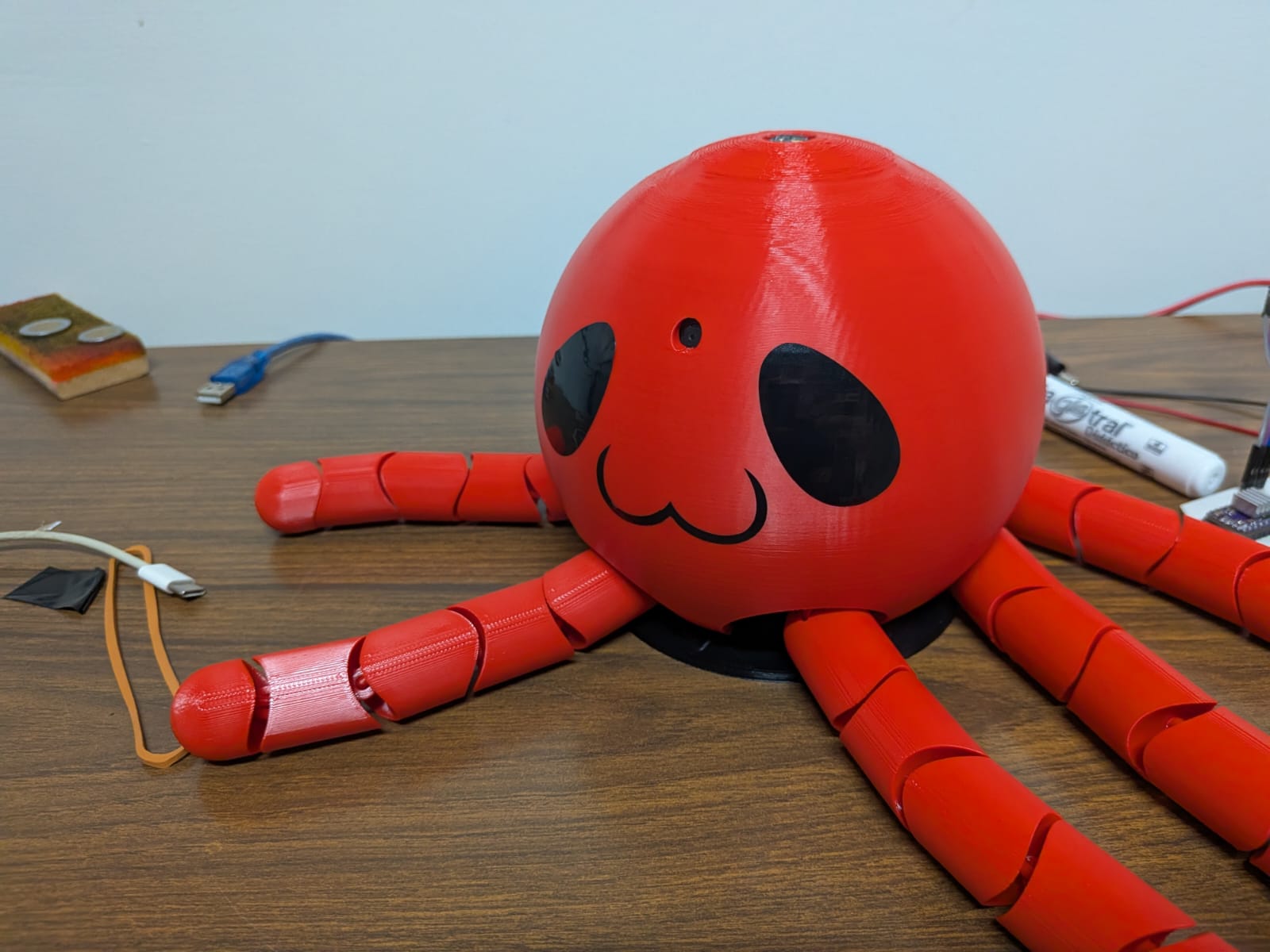
Our robo-octopus now has a personality of its own! The face turned out to look even better than I expected. The glossy nature of vinyl creates amazing contrast with the PLA, and you can even see your own reflection on its eyes.
June 5th
Testing The Rotating Base
My initial testing of the complete robot was not as expected. It turns out that, with the complete robot on top, the rotating base was not able to move. There where sounds of an attempt of moving and the whole base rotated a bit due to the vibrations of the stepper motor, which automatically discarded a problem with the motor. My initial hypothesis was that the motor had no enough torque to move the weight of the robot on top. I feared this would be the case, as it would mean that my whole rotating base was flawed.
An insufficient torque on my nema stepper motor models would mean that I would need to find another bigger motor. This option was, realistically, not possible for the following reasons:
- I’m using a personal nema stepper motor, which is the same model of stepper motor available for us students at our Lab. There are no other nema stepper models available.
- If I somehow where able to get my hands on a stronger nema stepper motor, I would need to redesign the whole rotating base to accommodate it, including:
- The rotating base casing (the one who cases the stepper motor).
- Every gear’s height, to accommodate for the longer shafts these bigger stepper motors usually come with.
- The squared perforation on my PCB, to accommodate for the dimensions these bigger stepper motors usually come with.
- Some stronger stepper motors require an advanced driver to work properly. There is a slim chance that my current driver (drv8825) wouldn’t be enough to power this new motor.
I took off the robot from the rotating base and examined what was going on. Without the robot the gears moved smoothly (like in my previous testing on the 360 Rotating Base section of this page). I tried to apply force to the planetary gear’s carrier, to simulate weight from the robot. Then I saw it: the stepper motor moved the sun gear perfectly until pressure was applied. When pressure was applied, the stepper motor’s shaft would keep spinning without moving the sun gear. This was a problem with my stepper motor’s shaft design, its a perfect cylinder. This design causes no problems when the attaching part is well secured to the shaft. However, the sun gear just slides into place. I needed two things: a new stepper motor with a flat side, for better grip, and a new sun gear that fits this shaft. Fortunately for me I had another stepper motor with the exact same dimensions and this shaft type.
I reprinted the new sun gear, and installed it and the new stepper motor into the rotating base. There where a few more problems to solve: For starters, I ignored that the shaft on this new stepper motor was longer, meaning that our connection plate no longer fitted where it is supposed to be. Secondly, the main problem persisted. Solving the first problem was easy. I just printed an extension for my base to adjust for that shaft length change. The second problem, though, was a little bit trickier to solve. With the new stepper motor the sun gear had a better attachment. But when pressure (weight) was applied to the carrier, the outer ring started to move. It turns out that, with planetary gear systems like this one, if the carrier is locked in place, the outer ring is the part that moves. We need the outer ring to be locked in place so that the carrier moves. I held the base with my hands and ran a simple rotation script to see what happened. Suddenly, the robot rotated correctly! So my theory was right: I need to lock the base in place, by either adding weight or actually fixing it to something.
Problem Solving: Laser Cut Base
Adding weight was discarded, as it wouldn’t solve the vibration problem (it could even worsen it). So fixing it into place was the better choice. I now needed to design and produce a new base, something where the rotating base can be fixed in place. This new base needed to be wide and heavy enough to prevent the base from moving. After some thought I came up with an idea: I would laser cut 4 identical MDF circles and paste them together. This way, I would have a big and wide enough base for my robot. I could even drill screws to it, which will come in handy for fixing the base in place.
I quickly created a circle in OpenSCAD. I then exported it in DXF format.:
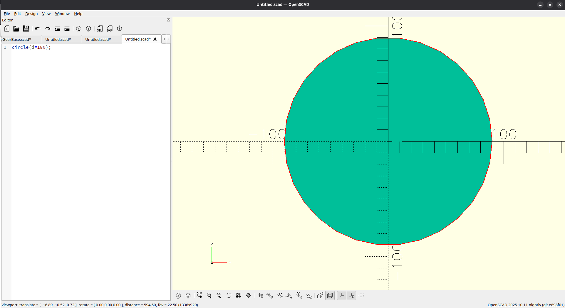
Then I took this file into our laser cutters, using the following parameters:
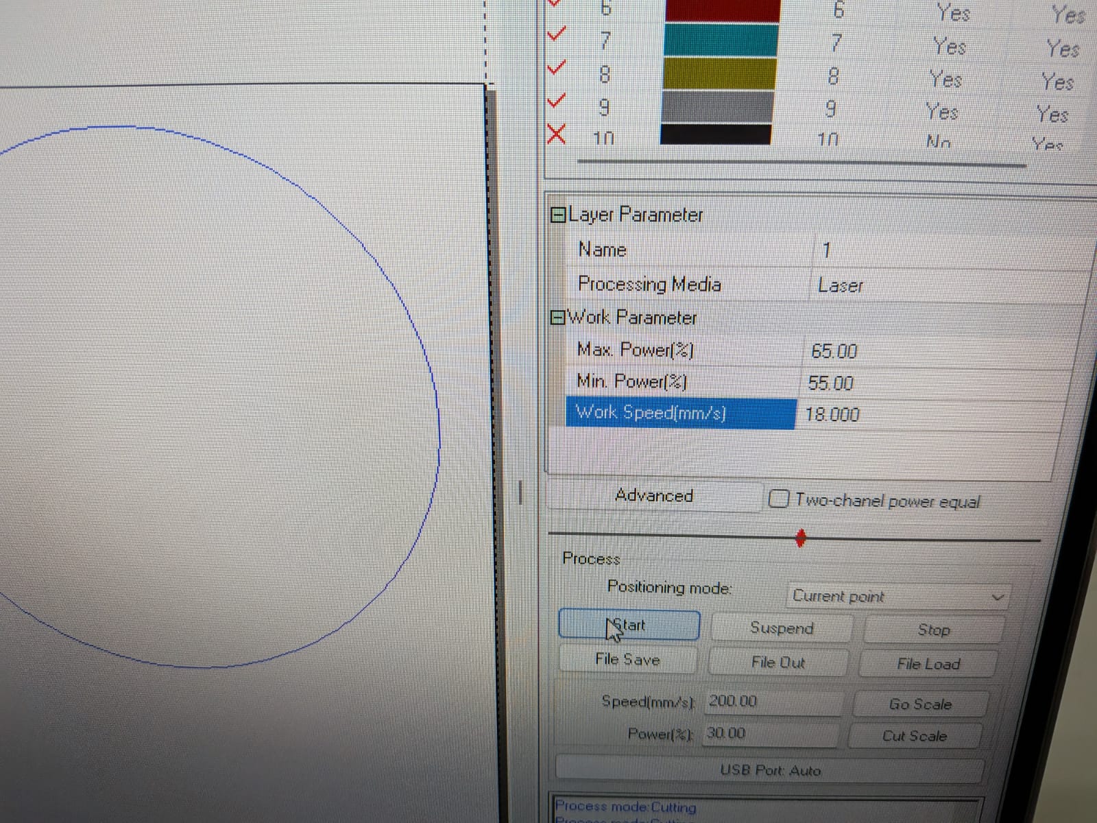
With the file ready, I printed a testing circle and the final 4 circles:
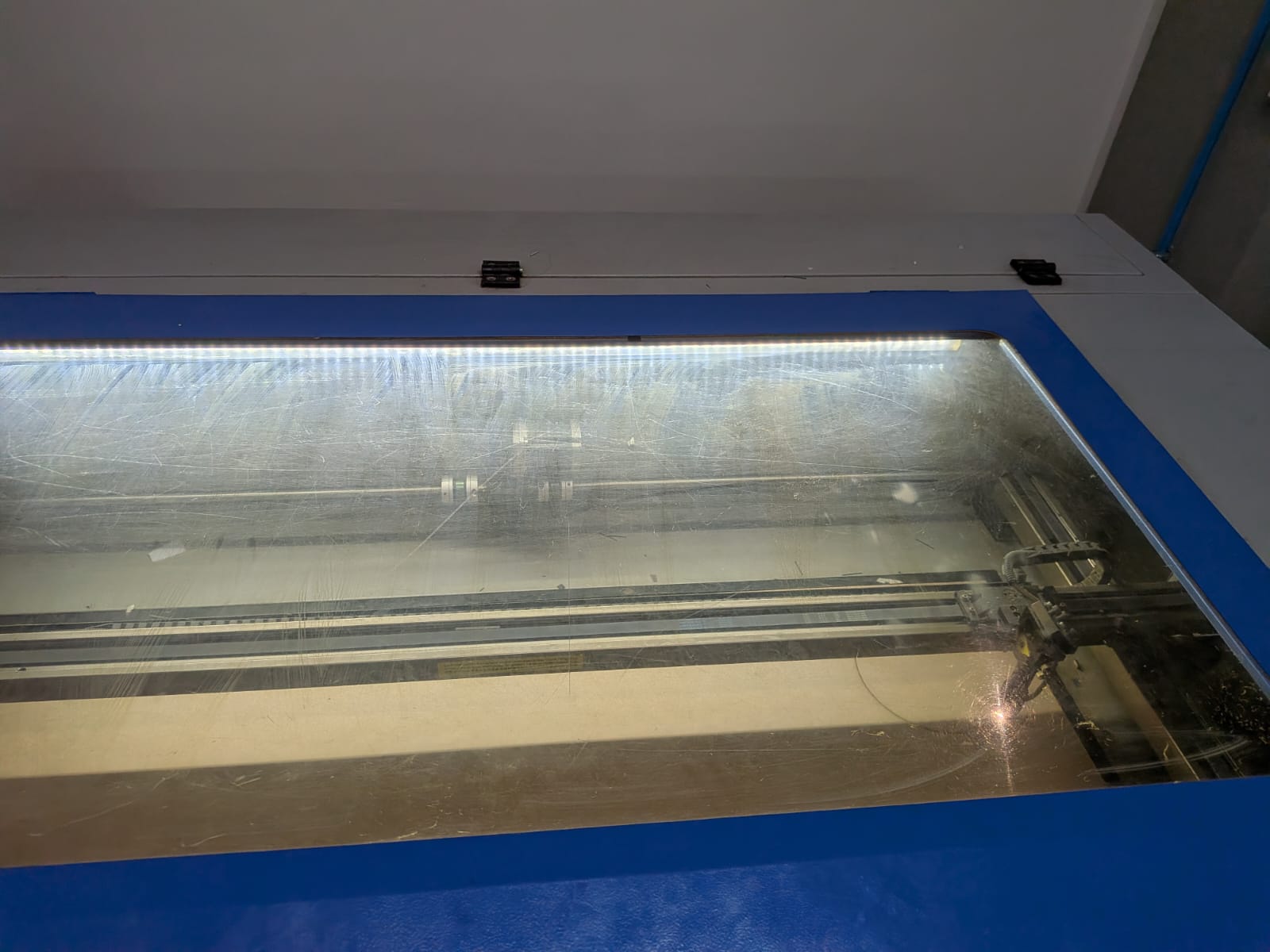
After that I retrieved my circles from the laser cutter. I used white glue (perfect for wood) to glue the circles together. I used some woodworking clamps to fix it in place whilst is dried.
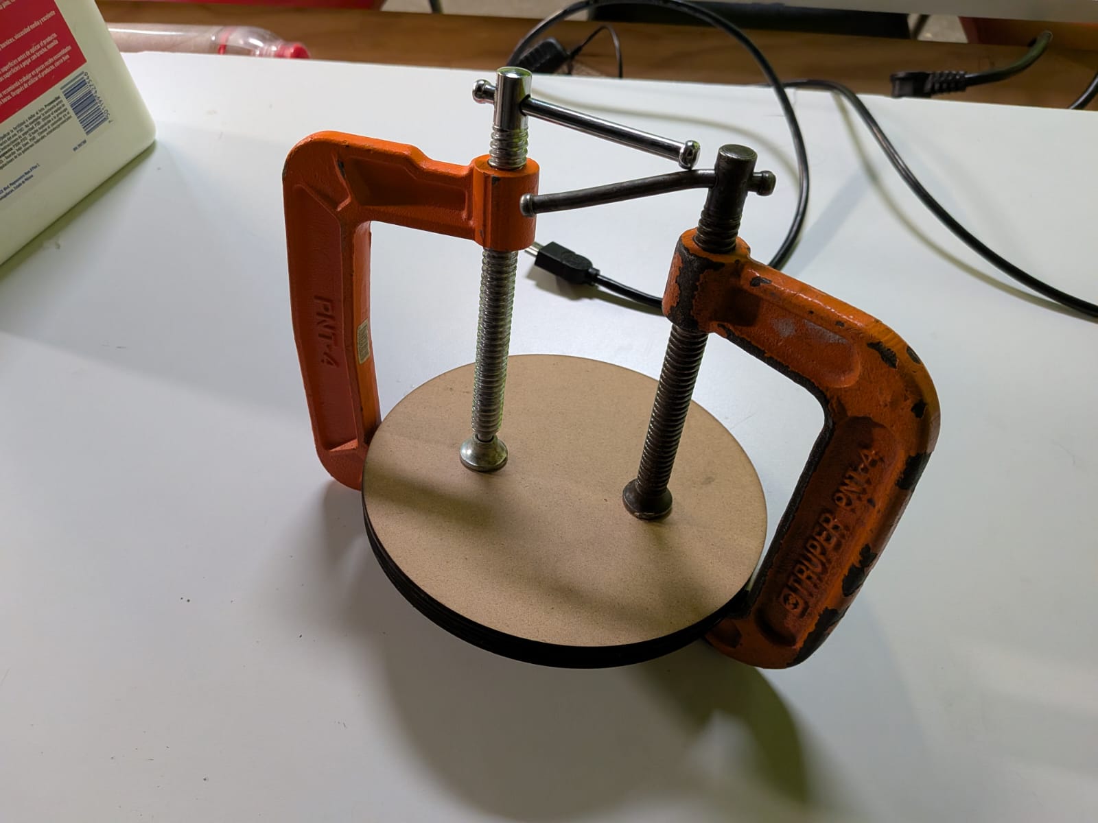
The base looked good, but a little rough. Pasting it as is would (hopefully) work, but it will not look as nice. So I decided to try and line it with vinyl. This will give it a better finish, and will look even better in my final project. So I booted up Inkscape and designed the vinyl lining. It was really simple, I just needed a circle the size of my base.
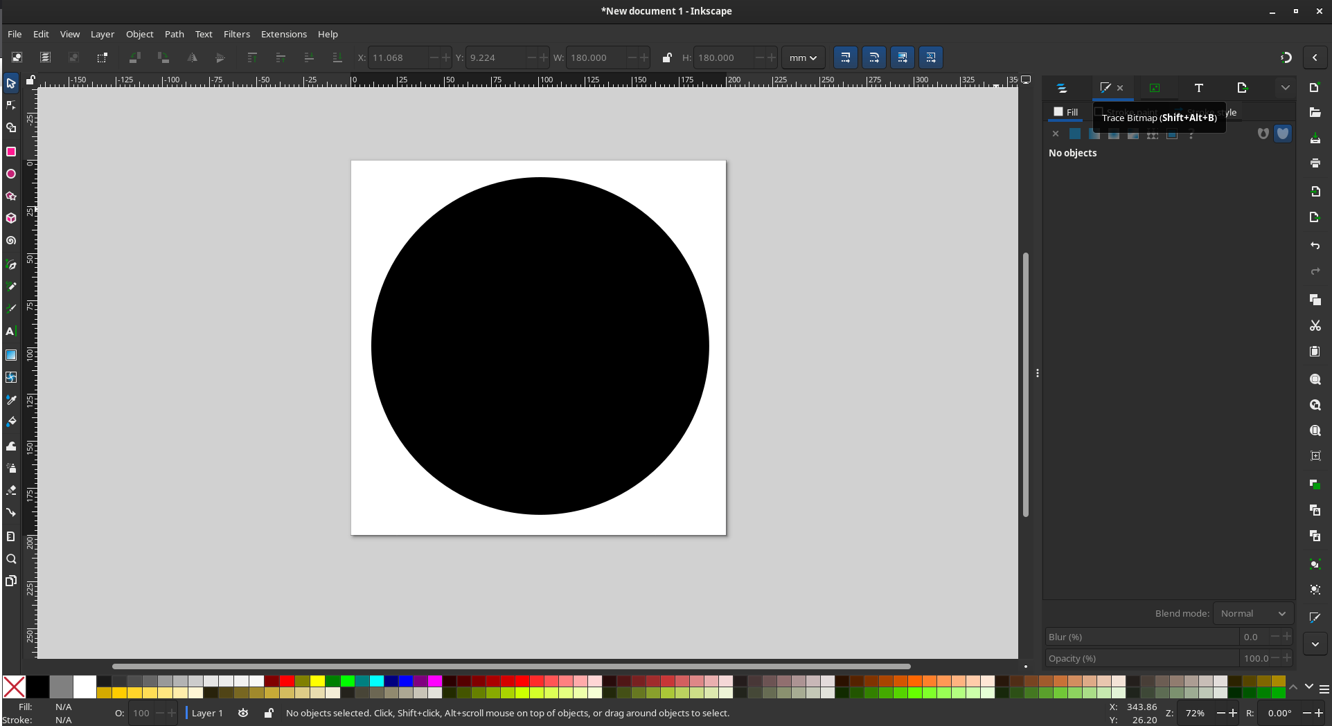
I exported it as a PNG. And while I was at it, I decided to designe a little something extra. I designed a “name tag” for my robot. This name tag will be pasted on the rotating base:

With this files ready, I returned to the vinyl cutter. The process was the same like with Otto’s face. I ended up with two vinyl shapes: The lining and the name tag.
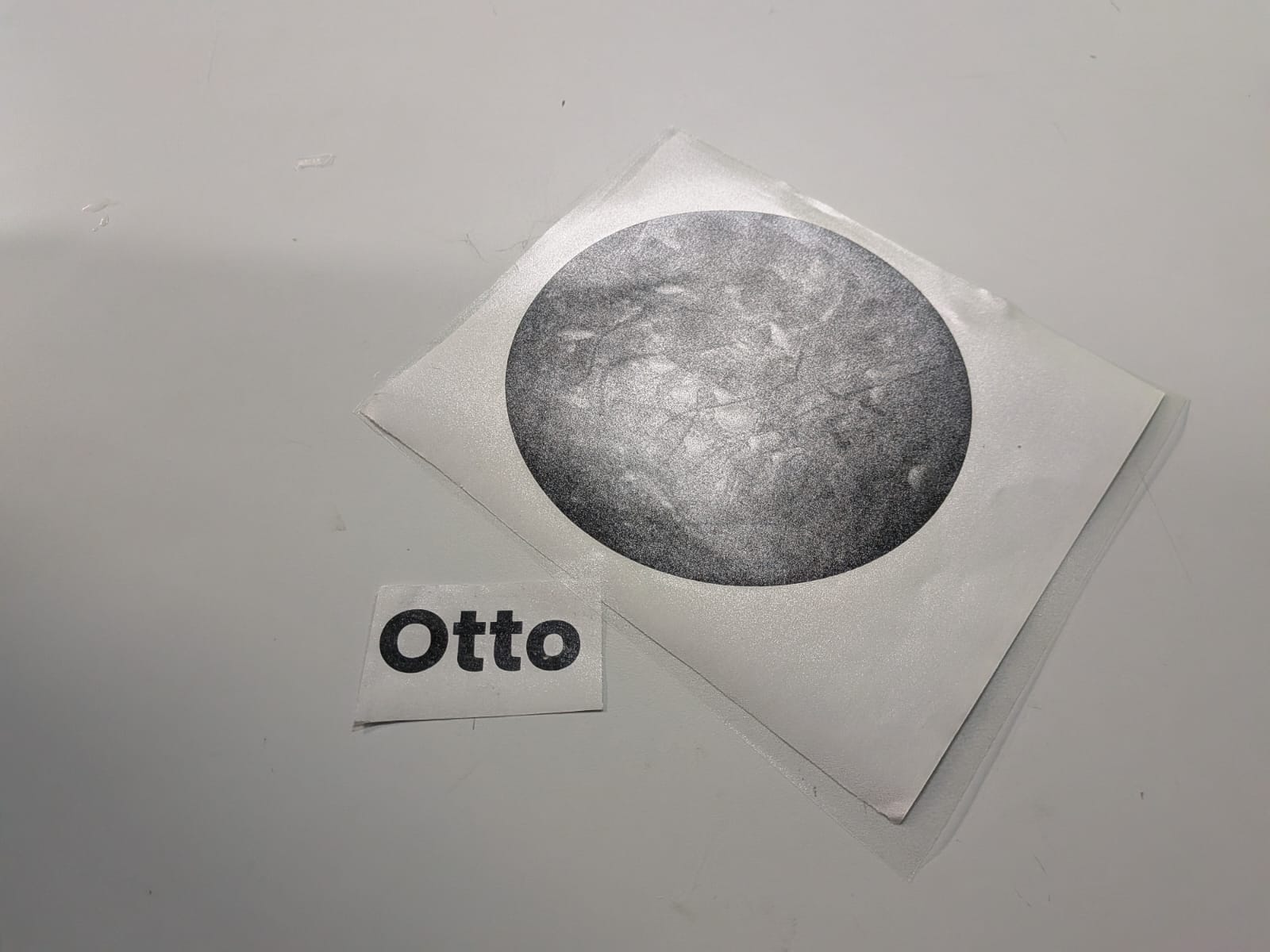
After applying the lining, I had a new base to fix my robot to. I now needed to design a way to connect the rotating base to this new base. I decided to attach 4 pieces to the bottom of the rotating base. This pieces will have screw holes, so that I could drill these screws through the pieces and the base, giving me a strong connection between them. I first designed the new pieces in OpenSCAD:
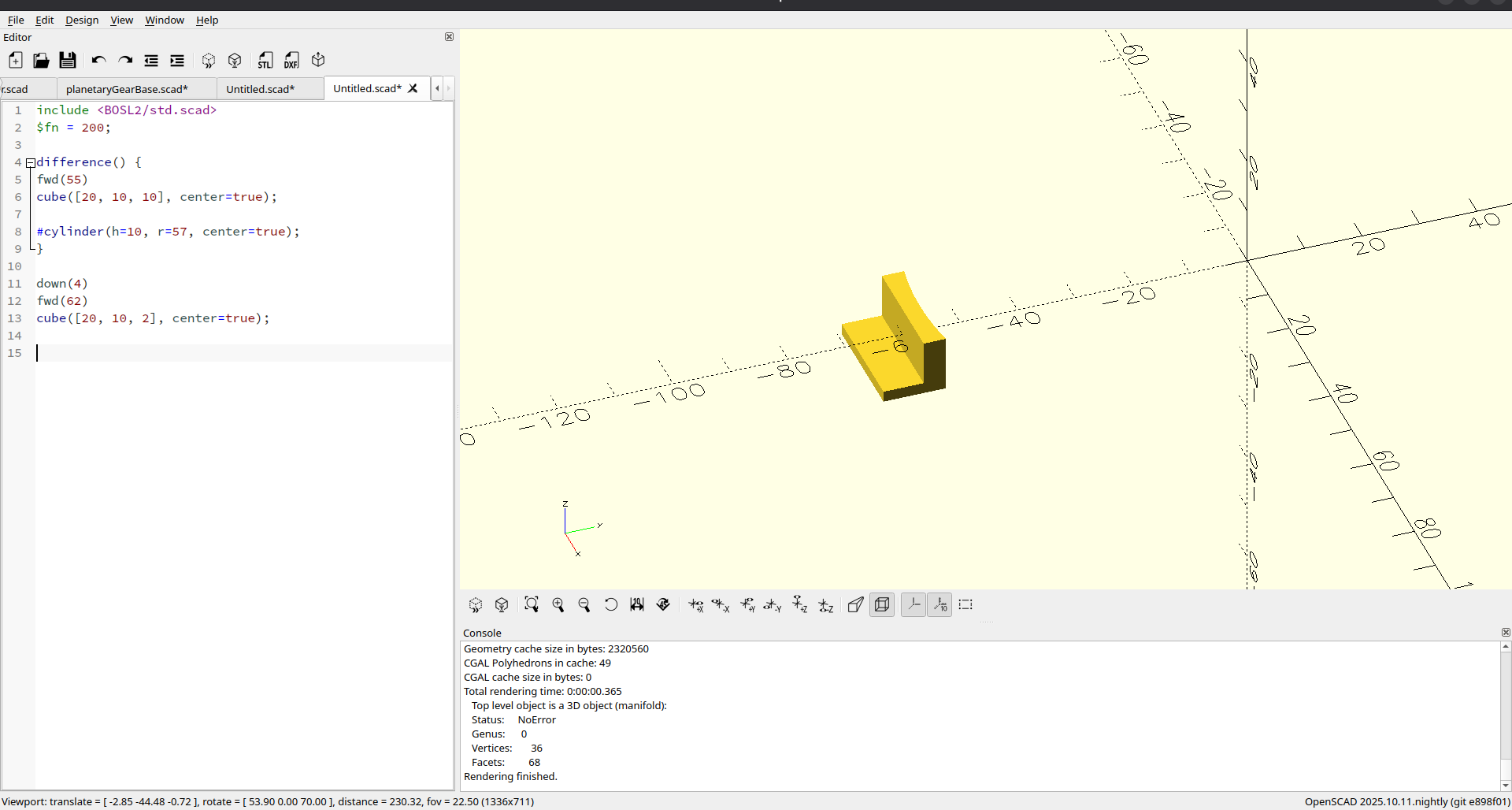
Then, I printed them out. It took some trial prints to get them exactly as I needed them to be. This was no problem, as each prototype took around 10 minutes to print. Once I got the perfect piece design, I printed the rest.
Before fixing this pieces in place, I ran a small test with a scrap piece of MDF. Using a small drill of my own I screwed the fixing piece and the MDF together. The drill had enough power to drill the screw, and the connection was really strong. I was ready for the next step. I was a little bit scared, though, as there was always a chance that drilling into the new base could separate the layers.
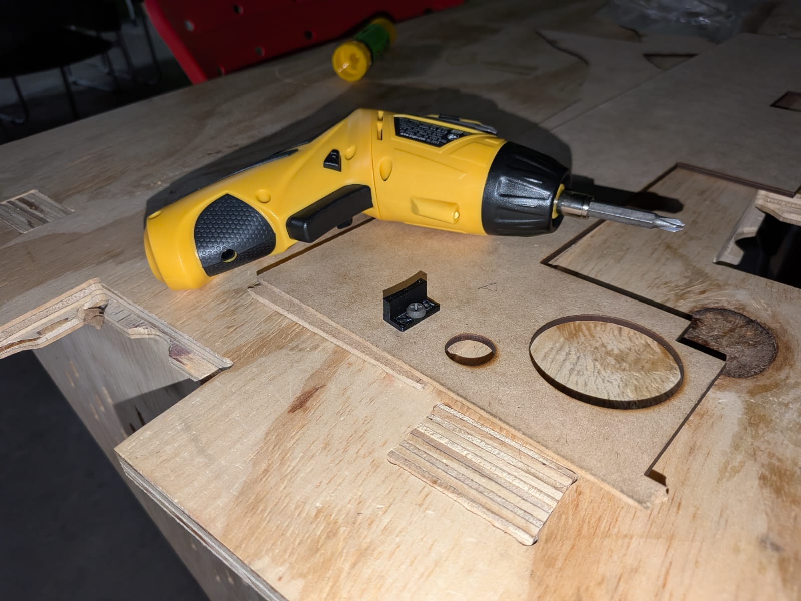
With everything ready to go, I pasted the connection pieces to the side of the rotating base using super glue, more specifically to the extension part I added to the rotating base. Ideally, I would have created an extension piece that already included the connection pieces, I didn’t know at the time of adding the extension piece that I would need connection pieces. I then marked the hole positions on the new base with red marker. I removed the rotating base and, with my drill and screws, I created the screw holes on the new base. The base stayed together with no problem, meaning I had nothing to fear. Once the holes where ready, I drilled the rotating base.
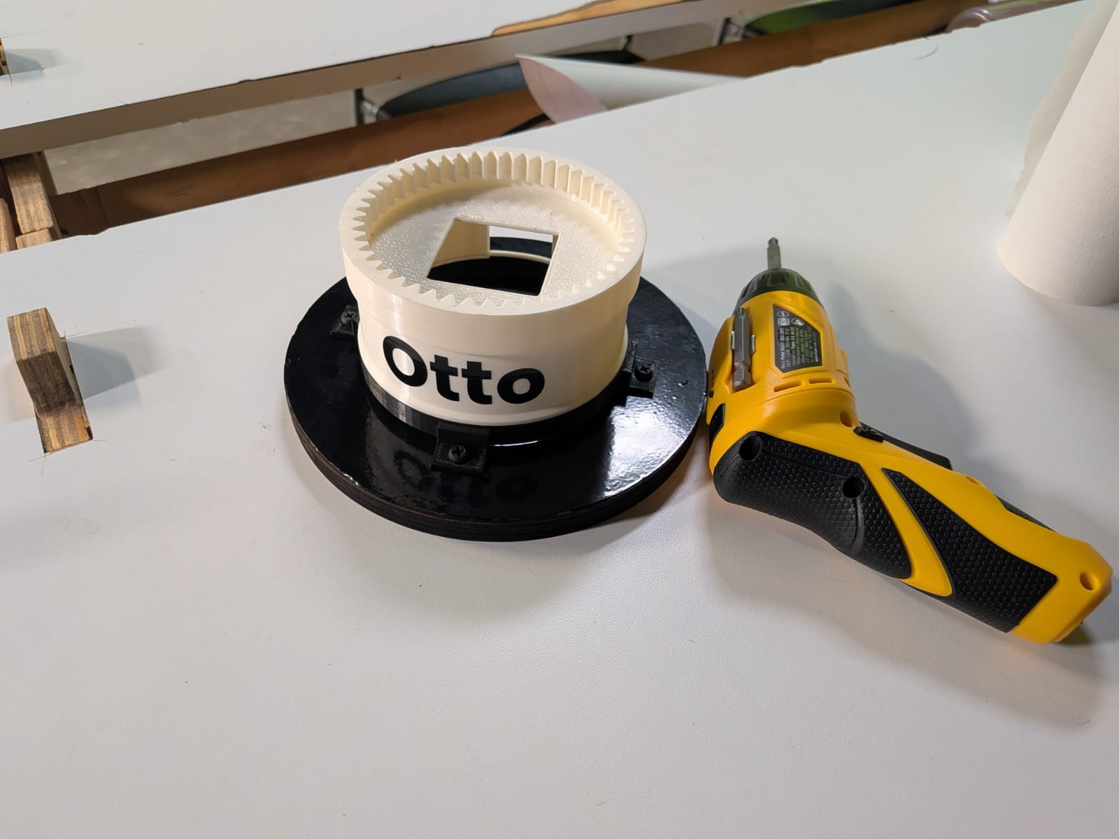
I immediately ran a test with the robot on top, with a simple script that moved it side to side. It worked perfectly!
This base solved the last issues that surged from this assembly part of the process. It really comes to show that things can go wrong, even in this penultimate step. Now that the assembly was ready, it is time for the final step: Testing.
Final Battery of Tests
Now that the last problem with the robot was solved, it is time to run the last battery of tests before calling my project a success. This battery of tests looked for testing the main systems of the project. These are the test we have to make:
- AI test: Raspberry Pi 5 script working correctly (including TTS and STT).
- Rotation Test: Rotating base working correctly (using a testing script).
- Tracking Test: Person tracking working correctly (only running tracking without AI).
When all of these tests are completed, the robot should work as hole, finally completing my project’s development.
Note: In reality we’ve already been testing each system on their own at key steps on their individual development, as you have been seeing mainly in the Mechanics and Programming sections of this page. For this reasons, these lasts tests are aimed at their complete functioning.
Rotation Test
The rotation test was the first one to be checked off the list, as we’ve just tested it in the section above. A thing to note here is that, in previous sections of this page, I stated that the turning ratio of the motor and the planetary gear system was virtually 1:1. I was wrong, it was always 5:1 as I initially calculated. The 1:1 ratio I experienced was probably due to a misunderstanding of the behavior of the rotating base on my initial testing without the robot on top. It turns out is is quite hard to really appreciate the turning angle of the base without the robot’s face as the final reference point. Needless to say, I corrected this ratio and the base worked perfectly.
The Rotation Test was passed.
AI Test
For this test, I ran a couple of times the Raspberry Pi 5 script. I noticed that there was an issue with the script. The audio coming out of the speaker was being captured as prompts, creating a sort of “feedback” in the program. The robot was basically speaking with itself, with the answers of the previous prompt serving as the next prompt. It took me some time to find the problem but, essentially, I had made it so that the audio capture from the MEMS microphone worked as a daemon, or a computer program that works as a background process. This means that the microphone was always listening and creating a queue of speech to text info. Then, the program called for the next text in the queue, creating that feedback problem.
I didn’t know how to solve this problem by myself, as my analysis dictated that running the microphone as a background process was a must to achieve the text to speech functionality. I opted for AI assisted debugging with Claude AI, my go-to AI for coding. Claude AI solved this issue by just adding a “flush” method for the queue, cleaning it after every input from the user (wake words and prompts). Claude AI’s solution worked almost perfectly. There was a new issue generated: The first speech to text (the one for the wake word) worked fine, but the second one (the one for the prompt) received only a partial text, not the whole phrase. This was a problem with the new flush_audio_queue() function, more specifically the position it was placed on. It was placed just before the speech to text conversion for the user’s prompt, where it should have been right after the wake word confirmation phrase. I corrected the mistake, and got a functioning AI script once again.
With this, the AI Test was passed.
Tracking Test
Now it was time for the tracking test. If you’ve read all this documentation up until this point, you will now that I’ve been having problems with the Xiao Sense Camera’s capabilities of tracking persons. Please refer to the Person Tracking section of this page for a better explanation. In all that section, I explained that I wanted to use a Raspberry Pi camera module, but I couldn’t make it work correctly. I was actually able to make it work with help of my instructor Rafa. The problem was that we figured that out too late. Using the Raspberry Pi camera would have involved redesigning the whole robot’s casing, removing the support for the Xiao Sense and adding a support for the new camera. Plus, the solution was still not plug and play, as still needed to figure out how to allow OpenCV to use this camera. The traditional cv2.VideoCapture(0) method of using the device’s default camera device didn’t work. I needed to find a way to make it work.
I decided to keep the Xiao Sense, which meant that this test will be done with the Xiao Sense. Surprisingly enough, it did work. The tracking is not perfect. In the next video you can appreciate that the tracking is “janky” and “jittery”, and there are moments where the robot just “returns to place”. This is probably a symptom of the reduced frame rate of the Xiao Sense. The tracking script sends “incomplete” information, causing this “jittery” feel to the tracking. Plus, when the camera’s quality makes it so that the tracker looses the current person, causing that “return to home” movements on the video. With all that said, I had tracking!
Would using the Raspberry Pi camera have resulted in a better tracking experience? Most likely yes. But the purpose of this FAB Academy is to learn how to solve our problems. In the absence of a camera module, I went into a development spiral to try and make that Xiao Sense to work, from trying to load the tracking model directly into it to converting it into a web camera. Again, please refer to the Person Tracking section of this page. In my opinion, it was a “masterclass” on the engineering problem solving mentality, and how changing your point of view can change the outcome of something.
And, at last, the Tracking Test was passed.
My FAB Academy 2026 Final Project is completed.
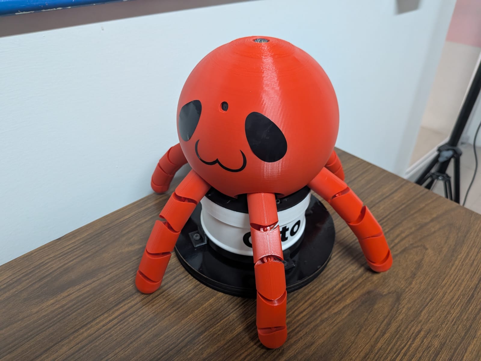
Files
The following zip files contains all the files created during the development of this project. All the files are separated following the Electronics, Mechanics, Programming strucutre of this page. Please consult the "README.md" file before navigating throught the project’s files. In this README file you can find a guide on each folder’s structure plus a description of each file. Also, the "LICENSE.md" includes the legal disclaimer for the Creatives Commons license used for this project.
- README File
- Final Project Electronics Files .zip
- Final Project Programming Files .zip
- Final Project Mechanics Files .zip
- Final Project Others Files .zip
- LICENSE File