CAD Software
CAD, or "Computer Assisted Drawing", is the art of sketching and modeling using software. CAD software help you by giving you tools and functionality to easily shape, sketch, model, and assemble your ideas. Knowing how to use CAD software is an essential skill to know in order to create any type of project that requieres custom pieces. For this FAB Academy, CAD usage is a must for 3D pieces´ design.
There are a lot of CAD software options out there, somo free and some open source. In this week, I'll be using some of this software to model a first preview of the pieces needed for my final project.
OpenSCAD
OpenSCAD is an Open Source Script based CAD software. Unlike every other CAD software with a GUI full of tools to draft and model 2D or 3D models, OpenSCAD consists mainly on a text editor and a 3D viewer. OpenSCAD transforms code into 3D models, using it´s own script. Plus, it's fully parametric, meaning that values can be changed on the go and the model will adapt to it. With a set amount of built-in objects and functions, and programming logic, OpenSCAD is a tempting option for user like me who understand code better than shapes.
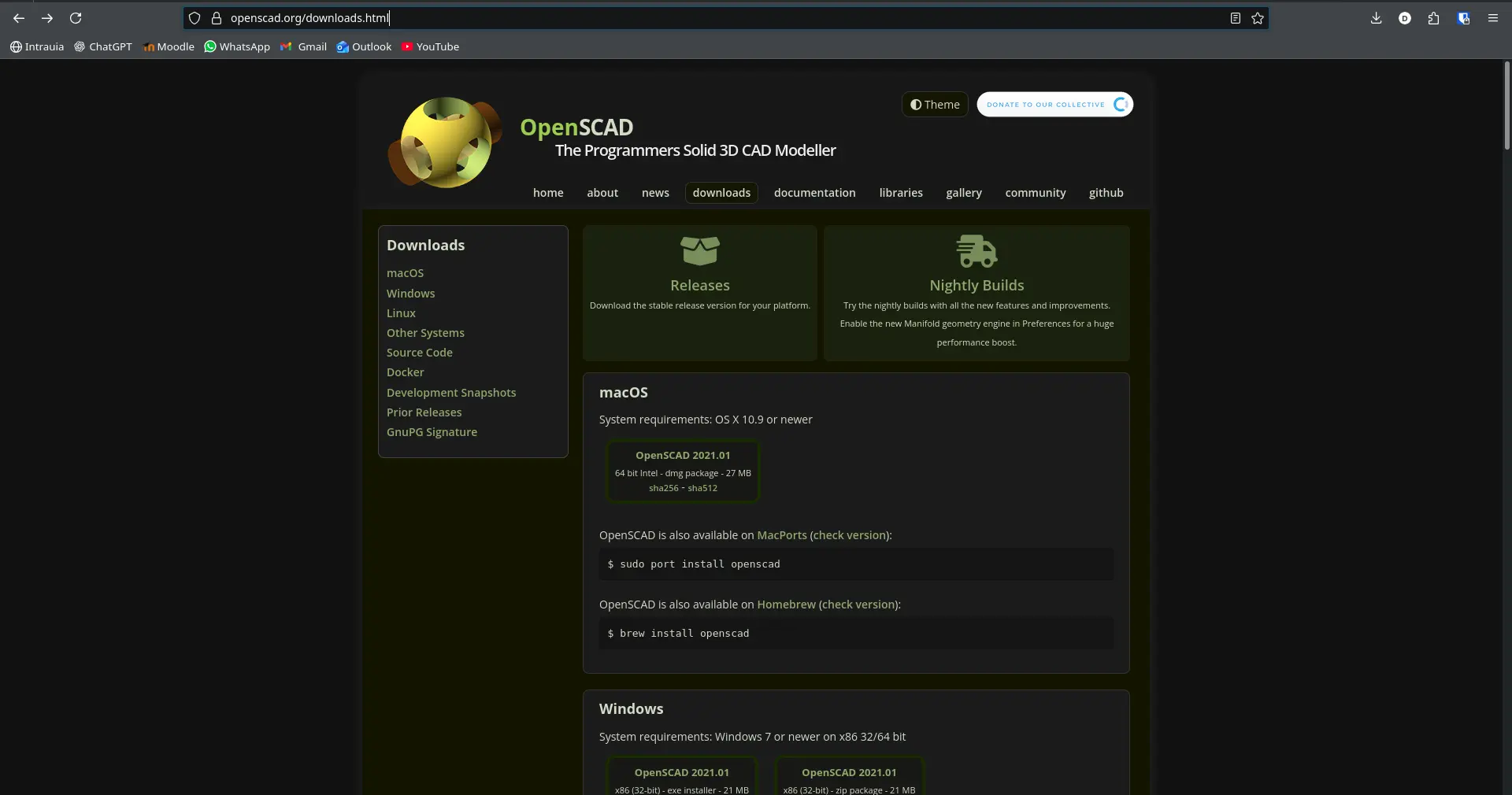
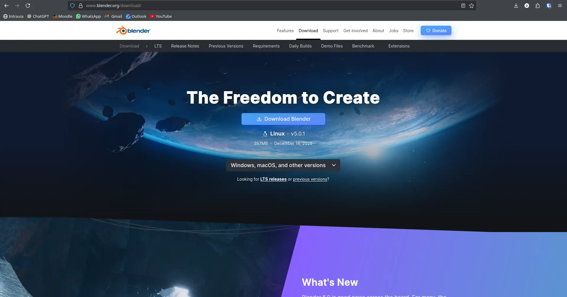
To use OpenSCAD you must first install it. You can download the latest stable version on OpenSCAD's main page, but I highly recommend installing the lates development snapshot, as it includes some features that will greatly help us with our modeling experience.
It's worth noting that, although OpenSCAD is a great CAD software, it comes with some disadvantages:
- You need to learn the scripting language: It's not hard to learn, you can follow this official OpenSCAD cheatsheet.
- There is a steep learning curve: Most CAD software out there is not script based, so abilities are not directly translated from these software to OpenSCAD.
- There are some limitations on what it´s easy to do: Organic figures, for example, are really hard to achieve in OpenSCAD compared to other software. OpenSCAD excels at symmetric, geometrical driven models.
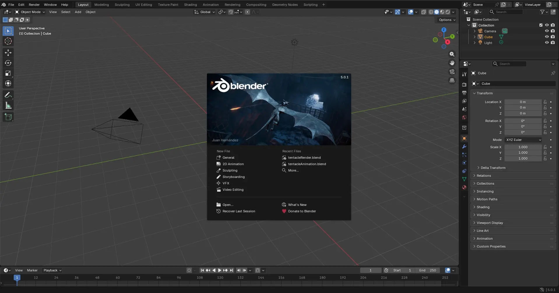
With that out of the way, we can start building our first model in OpenSCAD. Opening a new project will prompt you to this page:
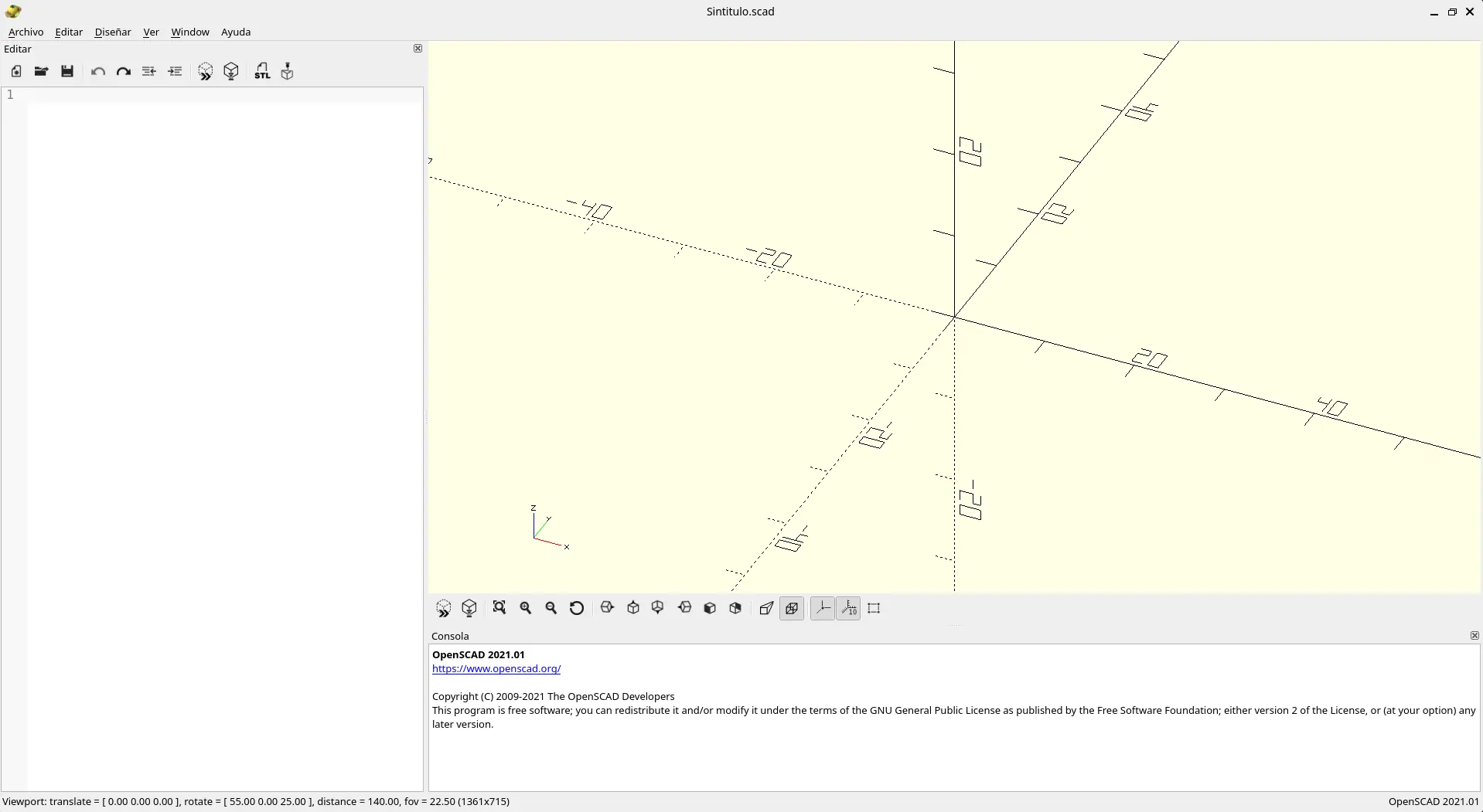
Here's a little tour on you workspace. On the left there is your text editor, where your code will be written. If you wish, you can use another code editor, like VSCode, to edit the file. Personally, I stick with the basic editor.
On your right there is your 3D viewer, where you can inspect your 3D models with basic movements like scaling, rotating and face views. Plus, you have a 3D axis and a scale for references. OpenSCAD uses "units" for measurement, the general consensus is that 1 unit is worth 1 millimeter. Underneath the viewer you have your console, where errors will be printed. If you like, you can close the console panel. It will always be available in Window > Console tab.
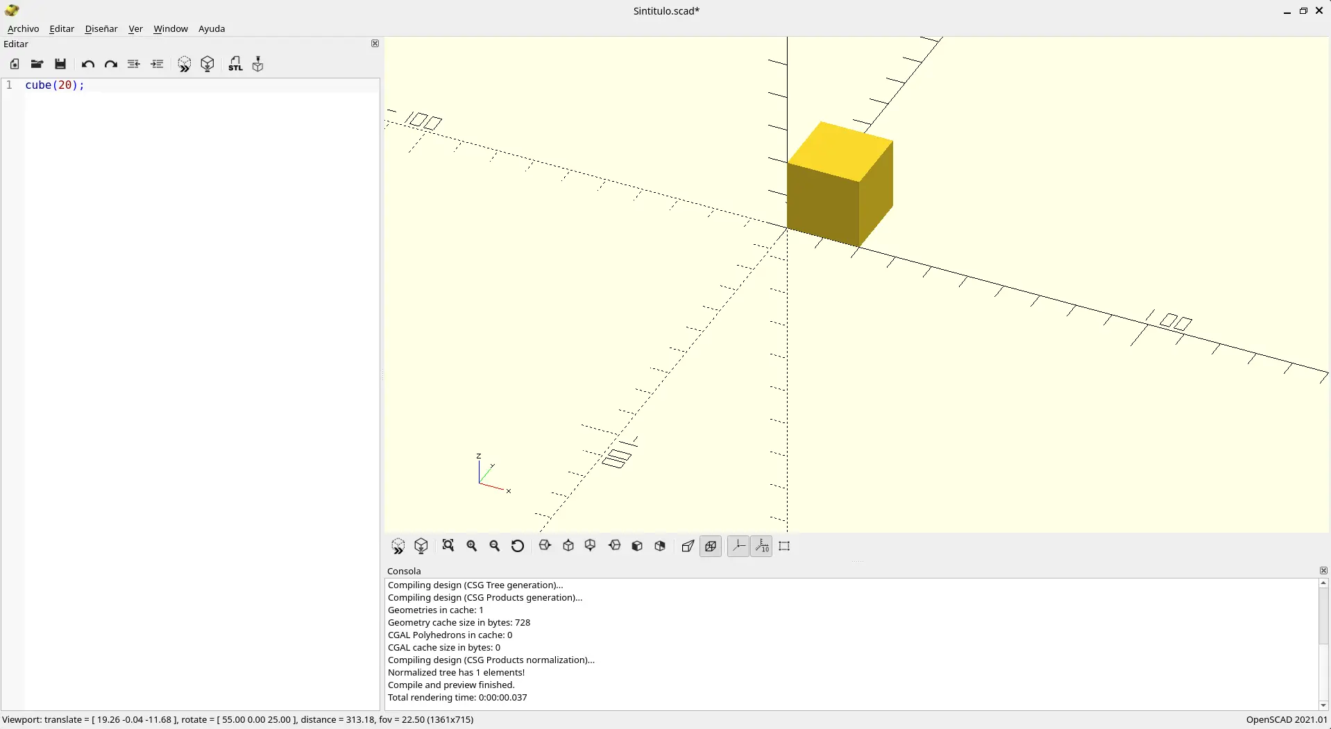
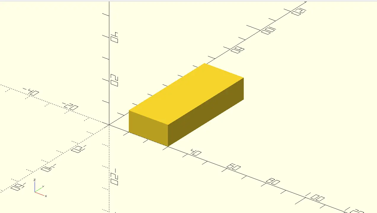
Let's start with a basic shape. In the code editor write cube(20);. After that, save your work and press F5 or the "Preview" button in the top of the editor to render your shape. To render your piece for exporting as .stl, you must press F6 or the "Render" button
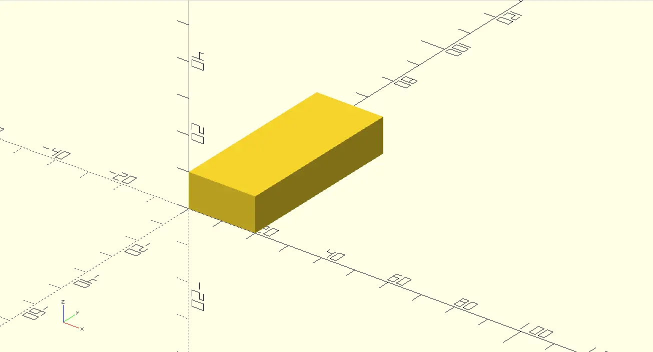
In your OpenSCAD cheatsheet there is a list of every 2D and 3D shape available to you, as well as the parameters they allow. For instance, if we want our cube to be a rectangle, we can change our code to cube([20, 50, 10]), for example. I highly recommend having your cheatsheet opened in a second tab at all times.
You can also modify your 3D model with transformation functions. For example, to move your model 10 units in the x axis, you must write translate([10, 0, 0]) on top of your figure, without ; at the end.
translate([10, 0, 0])
          cube([20, 50, 10]);
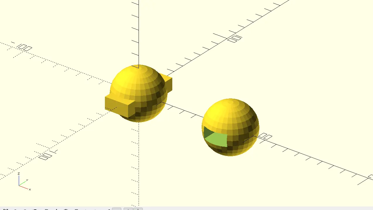
Other important transformation functions I'd like to showcase are union() {} and difference() {}. For those with CAD experience you might recognize this functions. Unions sum the area of all objects declare inside its brackets. Differences, on the other hand, rest the area of all the objects from the very first object declared inside it's brackets.
// Object union example
          union() {
              sphere(20);
              cube([20, 50, 10], true);
          }

          // Object difference example
          translate([80, 0, 0])
          difference() {
              sphere(20);
              cube([20, 50, 10], true);
          }
The last two important functionality to learn are the module() declaration and the $fn global variable.
A module is like creating your own personalized piece that you can use anywhere you want, including other files (this will be necessary later on) . To use this just type module piece_name () {}, chaining "piece_name" with your piece's name. Now, move anything that conforms your piece inside of it's brackets. If you try to render this, you won't be able. You must add a piece_name() declaration somewhere outside your module declaration. Now you can see your piece.
module my_box() {
              cube(20);
          }

          my_box();
The $fn, or "face number", variable declares the amount of faces your render will have. When previewing your model, use a small number like 50 for speed. When rendering for export, use a larger number like 100 for quality.
And with that, you are set to go and explore the possibilities of this CAD Software.
Blender
Blender is an Open Source software aimed at 3D modeling. It's a standard software in the animation and video game industry for it's modeling capabilities, animation tools and rendering capabilities. With that said, Blender it's not the first option when it comes to our modeling necessities, simply because it's not meant for our current applications.
What Blender is useful for our current application is physics simulation. For this, we need out individual pieces .stl files ready to go. Then we need to install Blender.
Opening Blender for the first time, you need to create your new file. Once inside the Blender blank project, save it.
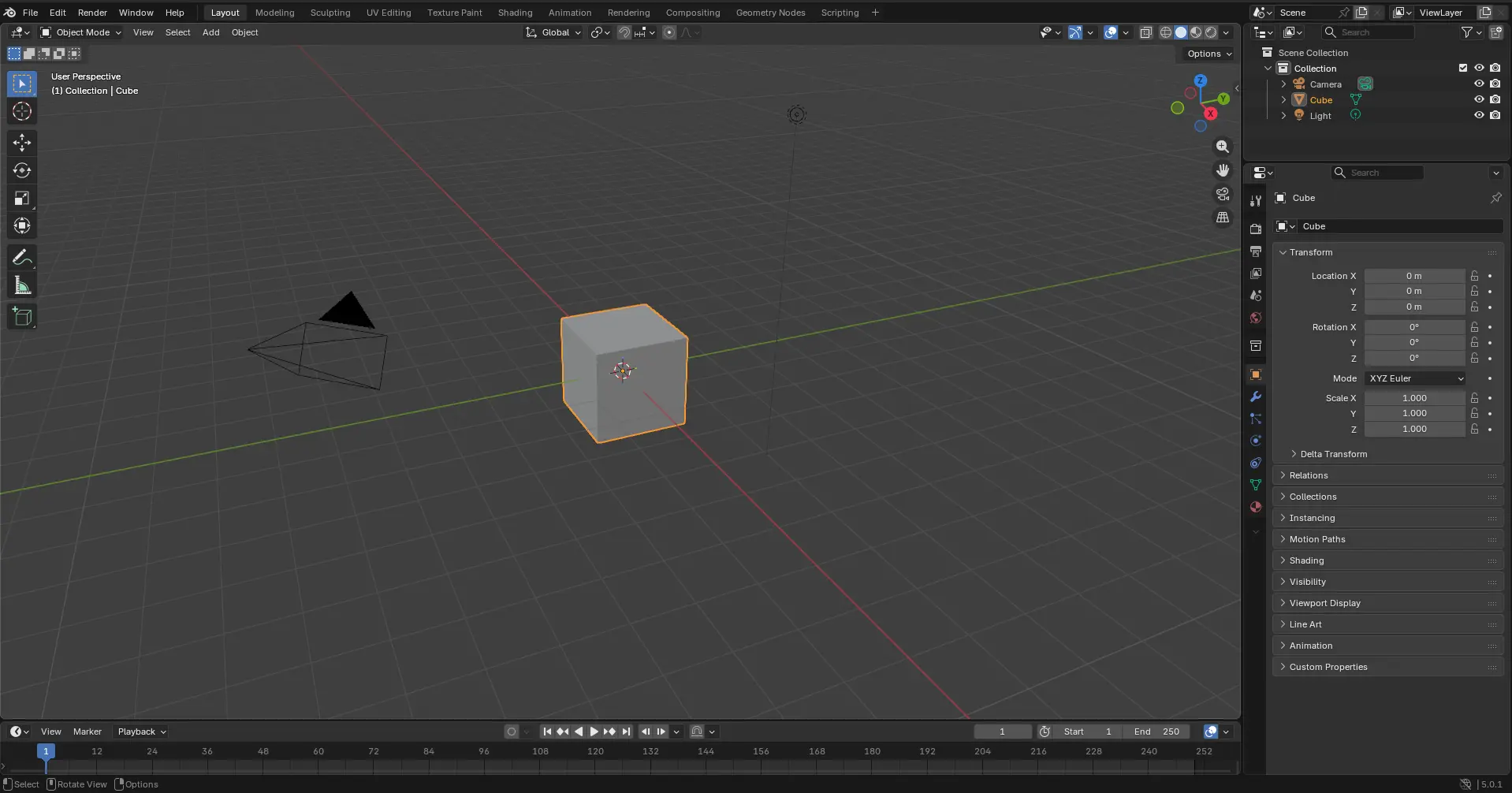
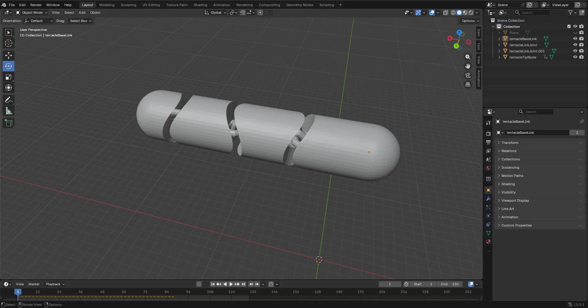
Now we need to bring our .stl files into blender. To do this, we can just drag and drop into the workplace. Remember, for the articulation effect to work, we need to import each piece individually, not the full tentacle model. Once our figures are in place, we can move them and rotating them using Blender's tools to place them into place.
Now, we give the tentacle some physics:
- Select your piece.
- Go to the tab under the objects tab, and select physics > Rigid bodies.
- In the options menu, change type to "Active" and shape to "Mesh".
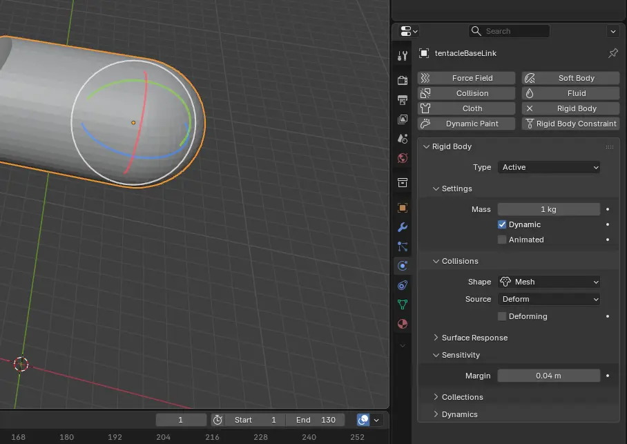
- Repeat for every piece of the tentacle
- Once every piece is configured, create a plain object by clicking SHIFT + A > Mesh > Plane.
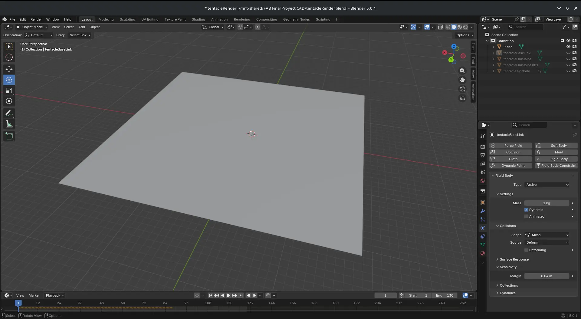
- Move the plane to your desired spot, below your tentacle.
- Repeat the physics configuration for the plane, but changing the type to "Passive"
- Now, press SPACE BAR. The tentacle will fall and collide with the plane, giving it motion.
Note: If your animation's FPS are slow, or the model does not behave correctly, it's probably because of your chain's face number. If you lower the face number (e.g. $fn = 20 in OpenSCAD), the problem might be solved.
Other CAD Software I tried
As I said before, I choose to go with OpenSCAD for my initial 3D modeling it this FAB Academy. But, taking in mind OpenSCAD's limitations, it is useful to experiment with other CAD software. There is a reason why profesionaly speaking, GUI based CAD like Fusion 360, AutoCAD, Solid Works, OnShape, etc. are the norm. The amount of tools and functions in their toolboxes allow the user to model any shape they desire, with the biggest disadvantage being the need to learn and master all this tools. Still, the objective of the FAB Academy is not to make you an expert of a single topic in one week. And with enough time and practice, this software will be a great addition to my personal maker toolbox.
Fusion 360
Fusion 360 is Autodesk´s solution on 3D modeling. Unlike other Autodesk software, like Maya or AutoCAD, Fusion 360 excells at paremetric design for robustly made models. This is a really complete software intented for profesional applications.
To start using Fusion 360, you first need an Autodesk account. Then you must purchase a Fusion 360 license. if you are a student, ask your institution if they have a student´s licence for you to download Fusion 360 and other Autodesk software for free. Once you have Fusion 360 installed, open a new project.
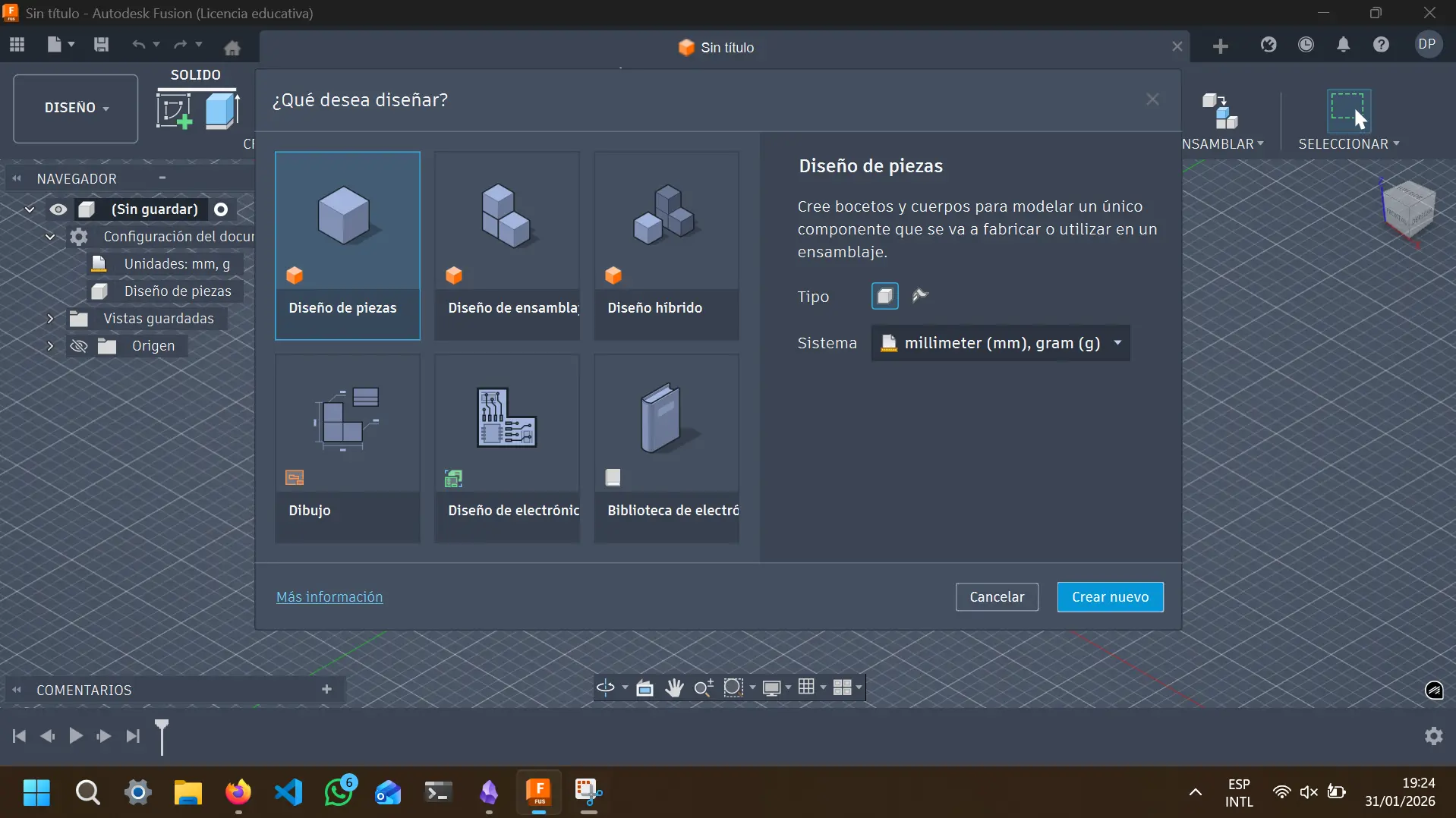
You will be prompted to select you design type. The main choices for us are "Single piece", for designing a single piece; or ''Assembly''., for designing multiple pieces to then assemble them together in a bigger model. For our use cases we will choose ''Assembly''. Then, you must select your measurments units. The standard is millimeters for lenght and grams for weight. Once your selection is ready, click ''Create new" to continue. You will then be shown your empty workspace:
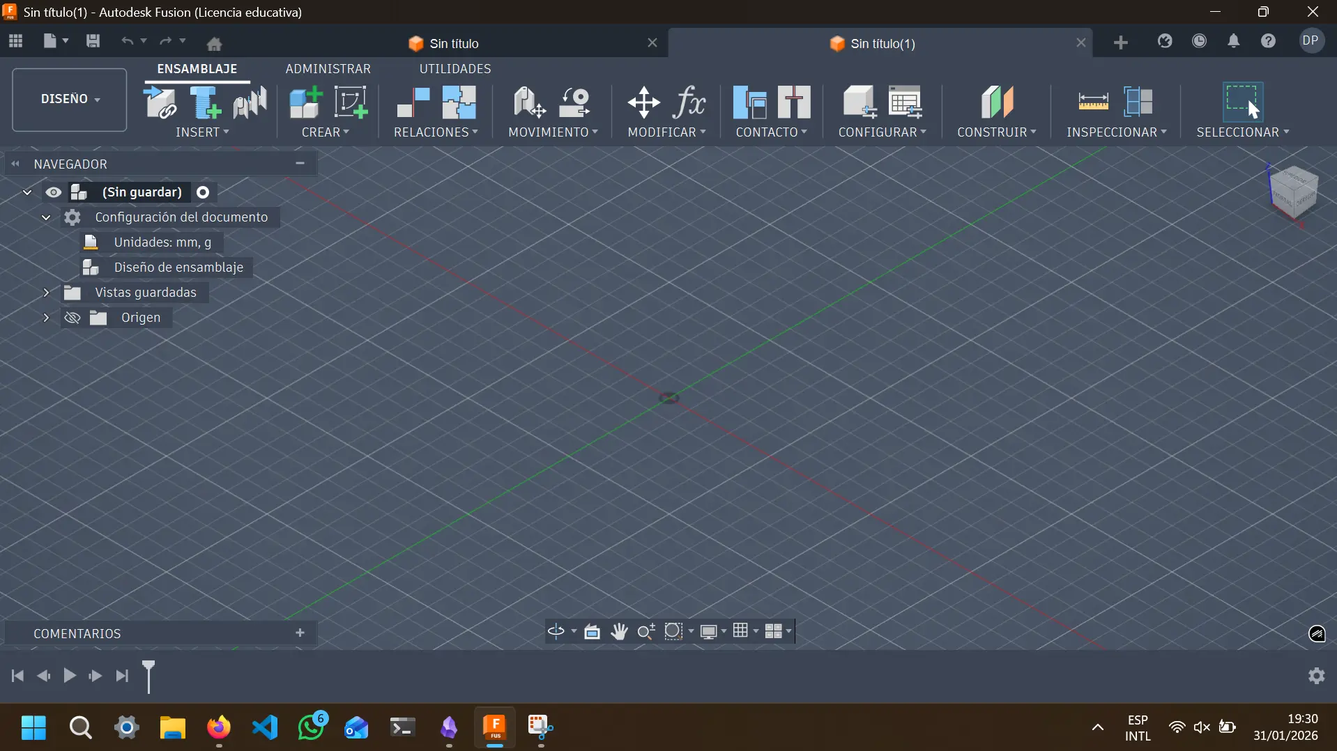
For new users like me, seeing the software´s blank project screen might feel intimidating. But once you understand where the main tools are and how to use them is more tha enough to get you going.
Note: For any new software like this you need to learn, searching ''Crash Courses'' on YouTube is one of my favorite strategies. Some of this videos are an hour long, and teach you the fundamentals of your software, giving you more than enough knowledge to get you going.
Fusion 360´s workflow goes sometihng like this:
-
Create a new piece (if you are in an ''Assembly'' project).
-
Sketch your initial figure in 2D.
-
Extrude to make it 3D.
-
Modify the object to your desired shape with every tool at your disposal.
-
Repeat steps 2 to 4 until your piece is ready.
-
Repeat every step until all your pieces are ready to go. Once then, you can make your final.piece joining them in a new file.
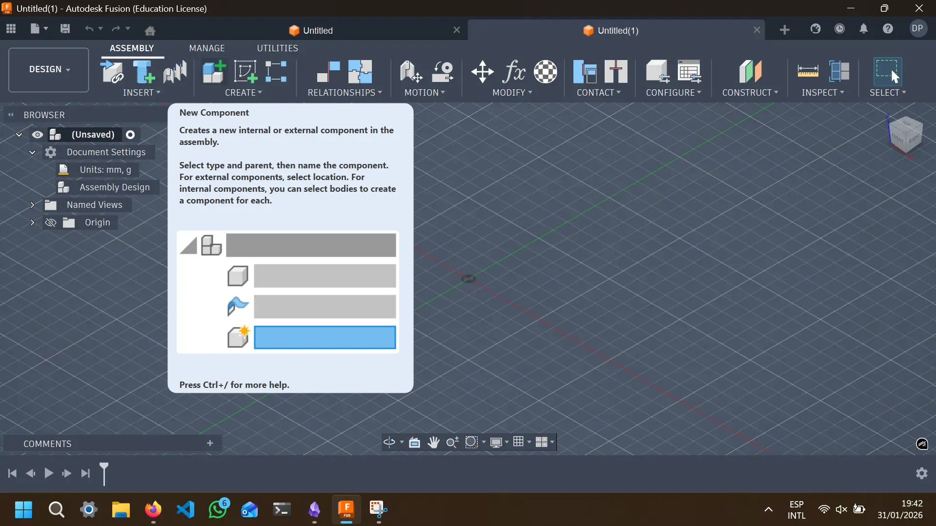
Let´s create a simple model using this workflow. Fisrt we create a new component, will call it ''iPhone'':
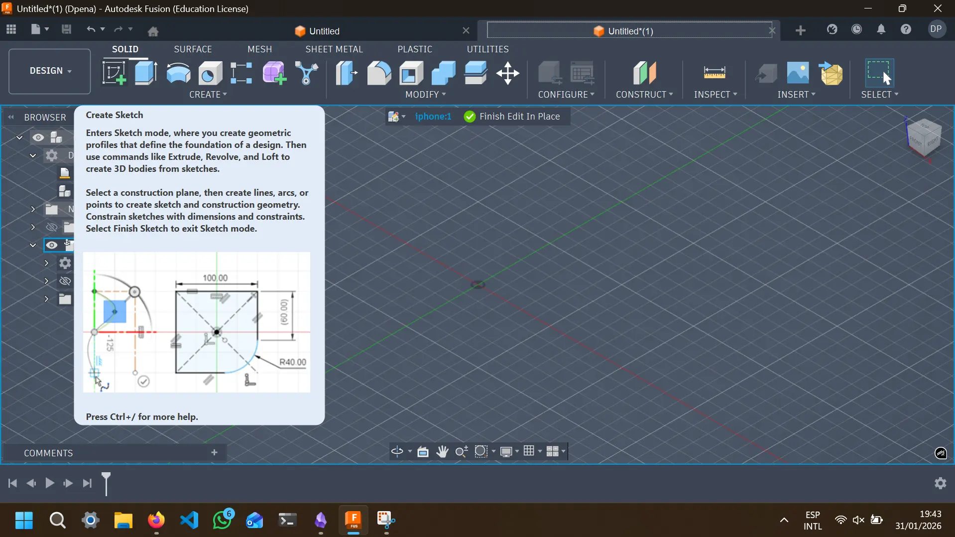
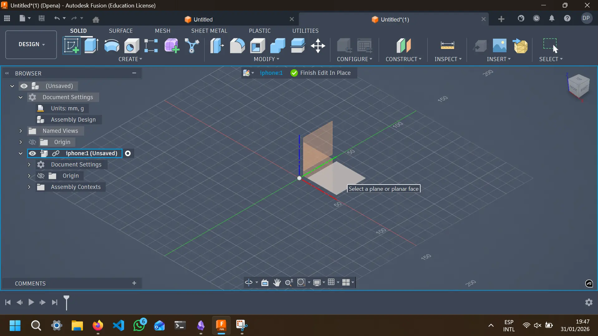
Then we make a new piece sketch. To do this, we must enter to the sketch workspace by clicking the ''Create Sketch'' Button, and select the plane you want to work in:
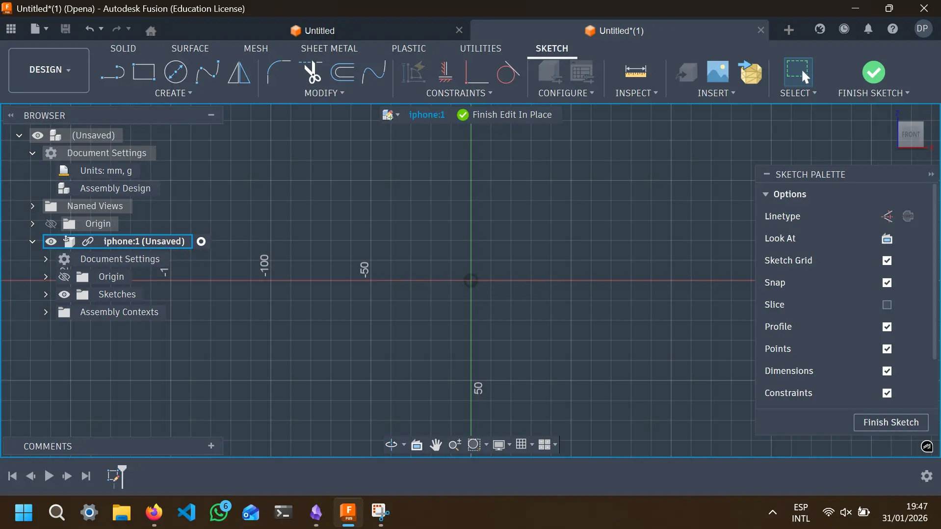
You are now in the sketch workspace:
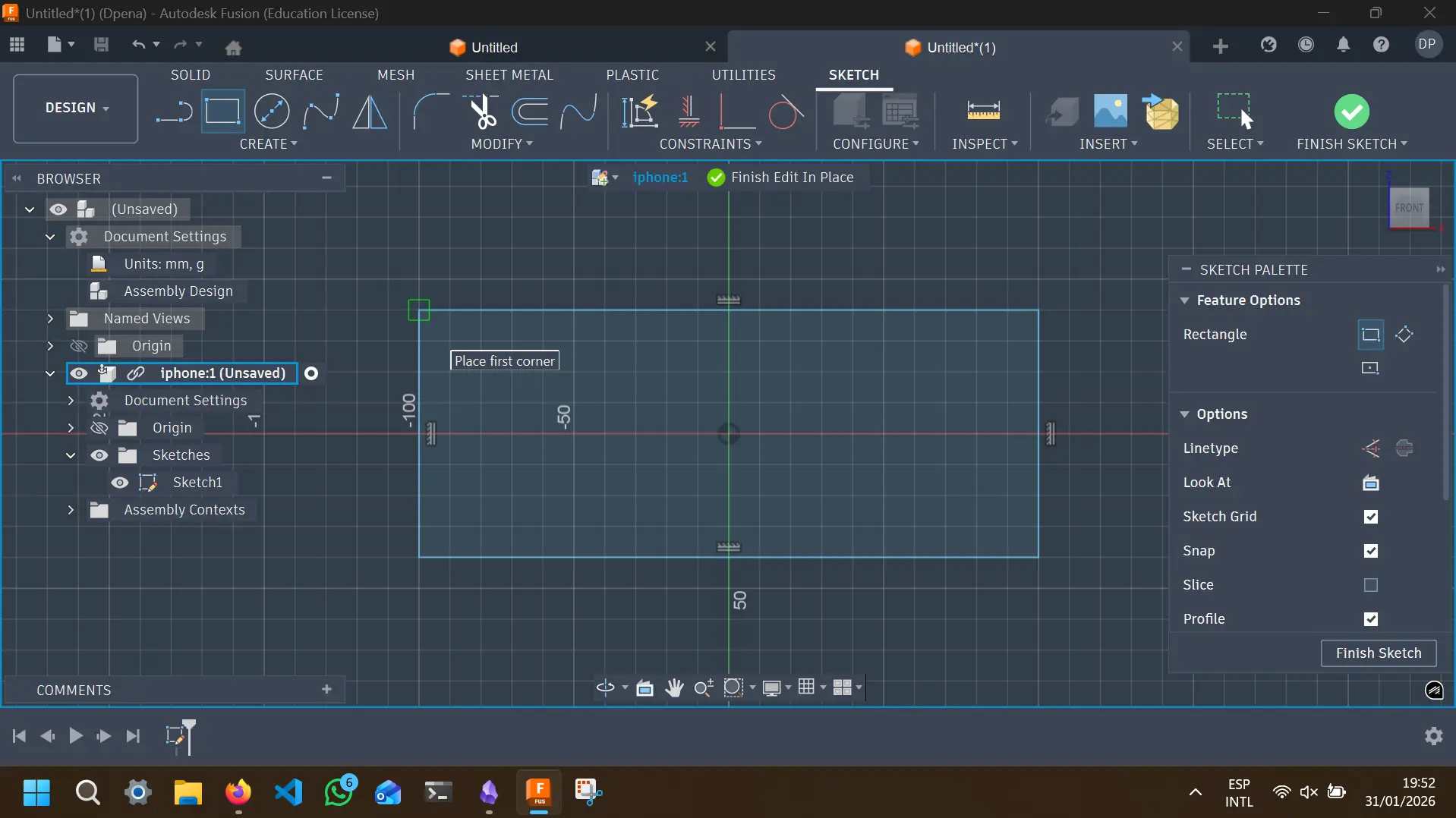
In this work space you must draw you piece in 2D. Remember, this piece is going to receive volume once the sketch is done, so plan accordingly. There is a plethora of tools to use, you can free draw your shape with lines or geometric figures. In this case, will draw a single rectangle, selecting the rectangle tool and drawing it:
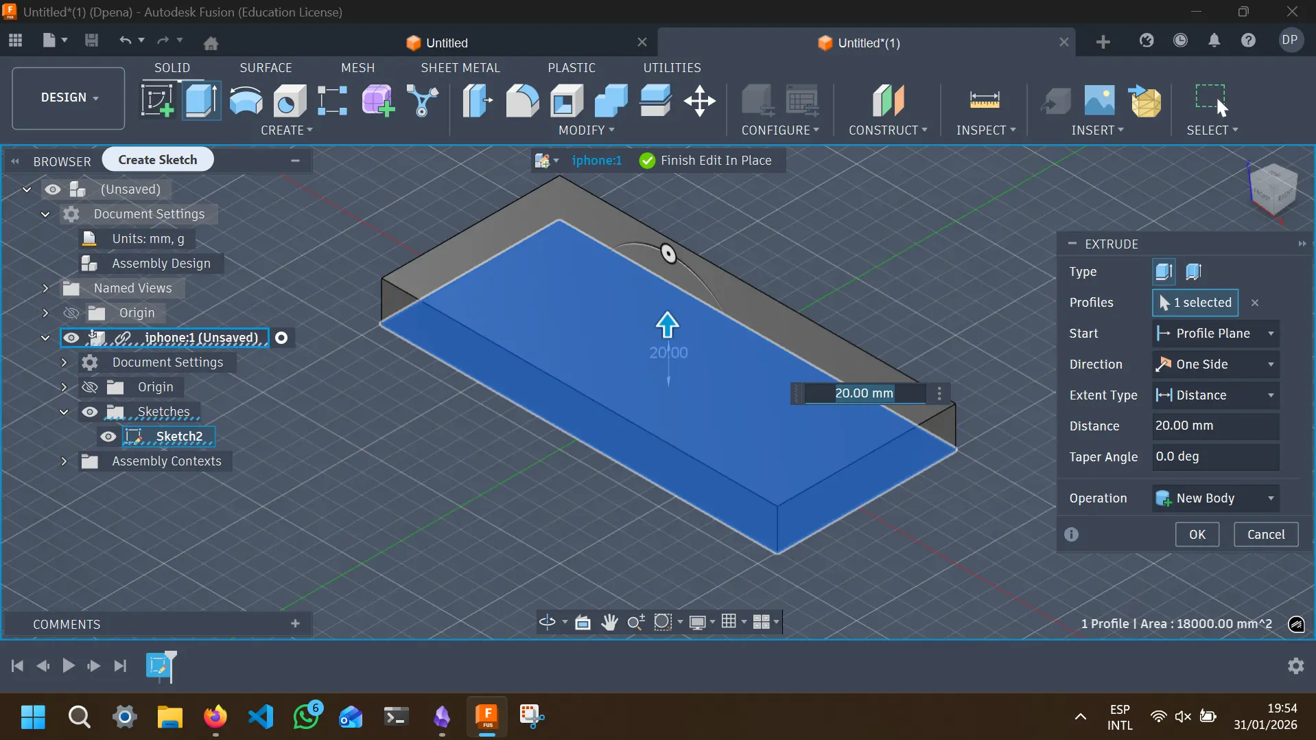
Once your sketch is done, select ''Finish Sketch''. You view will now change to the default screen. Now, using the ''Extrude'' tool in the toolbar (or presing E on your keyboard). Extend the figure with your mouse or by adding an exact measurment:
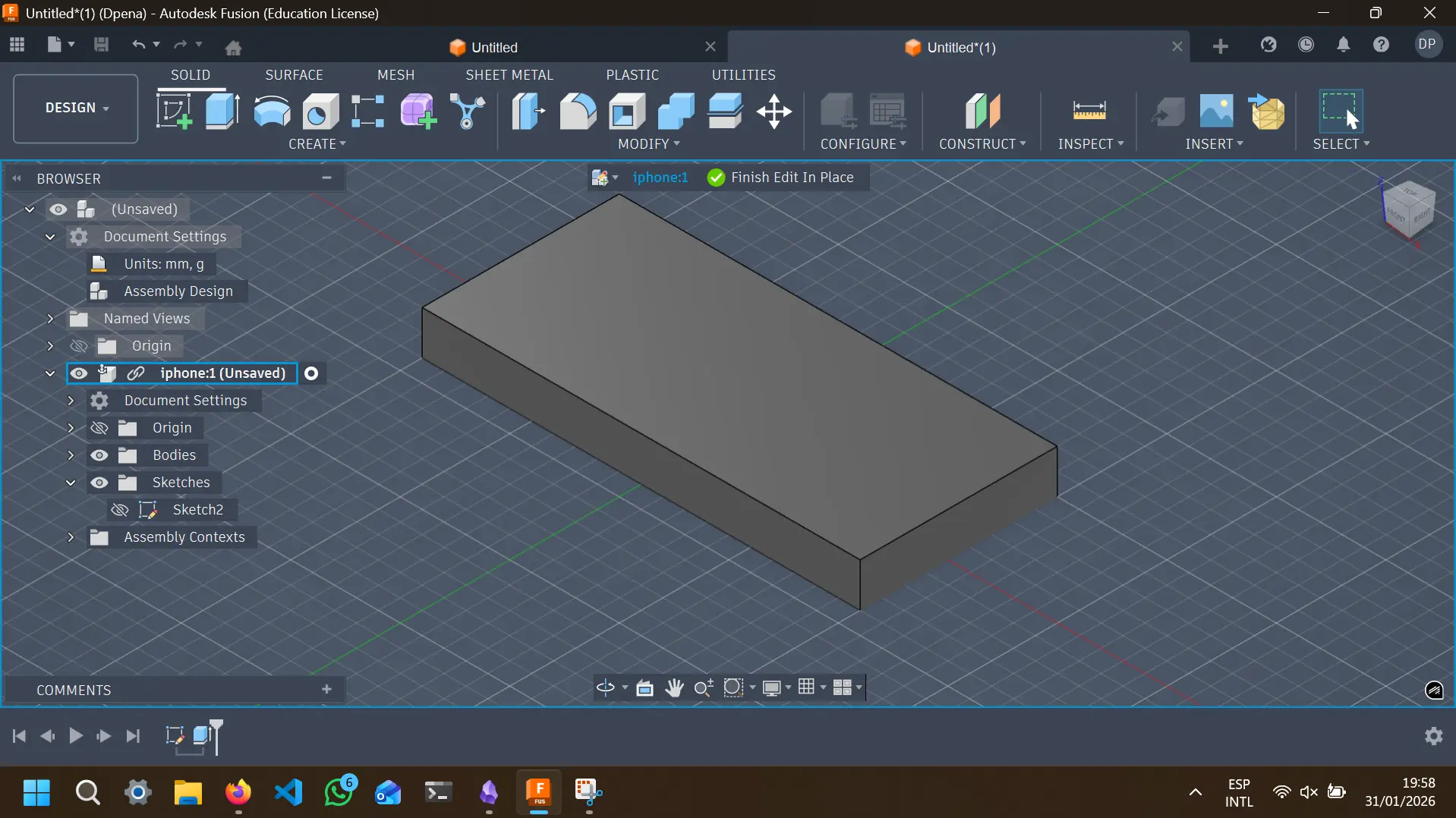
And there you have it! Your first 3D shape.
Now, repeat this lasts steps using all of Fusion 360´s tools to make your own 3D models. Remember, there is a steap learning curve, but once you get the hang of it, there is nothing you cannot create!
AutoCAD
With my Autodesk licence came AutoCAD, another standard in the industry CAD Software. The main difference between Fusion and AutoCAD, is that Fusion is better at 3D modeling and AutoCAD is better at technical drawing. Sketching a project in 2D before modeling it in 3D might feel like a useless step, but is crusial to correctly document your work and scaling it into something bigger than a personal project.
AutoCAD´s GUI is similar to Fusion´s, even easier once we consider that with AutoCAD we´ll be mostly drawing in 2D.
To use AutoCAD (asuming it is already installed), open a new proyect. You´ll be prompted to the blank project screen.
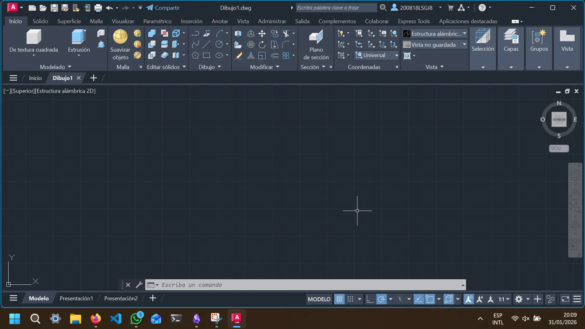
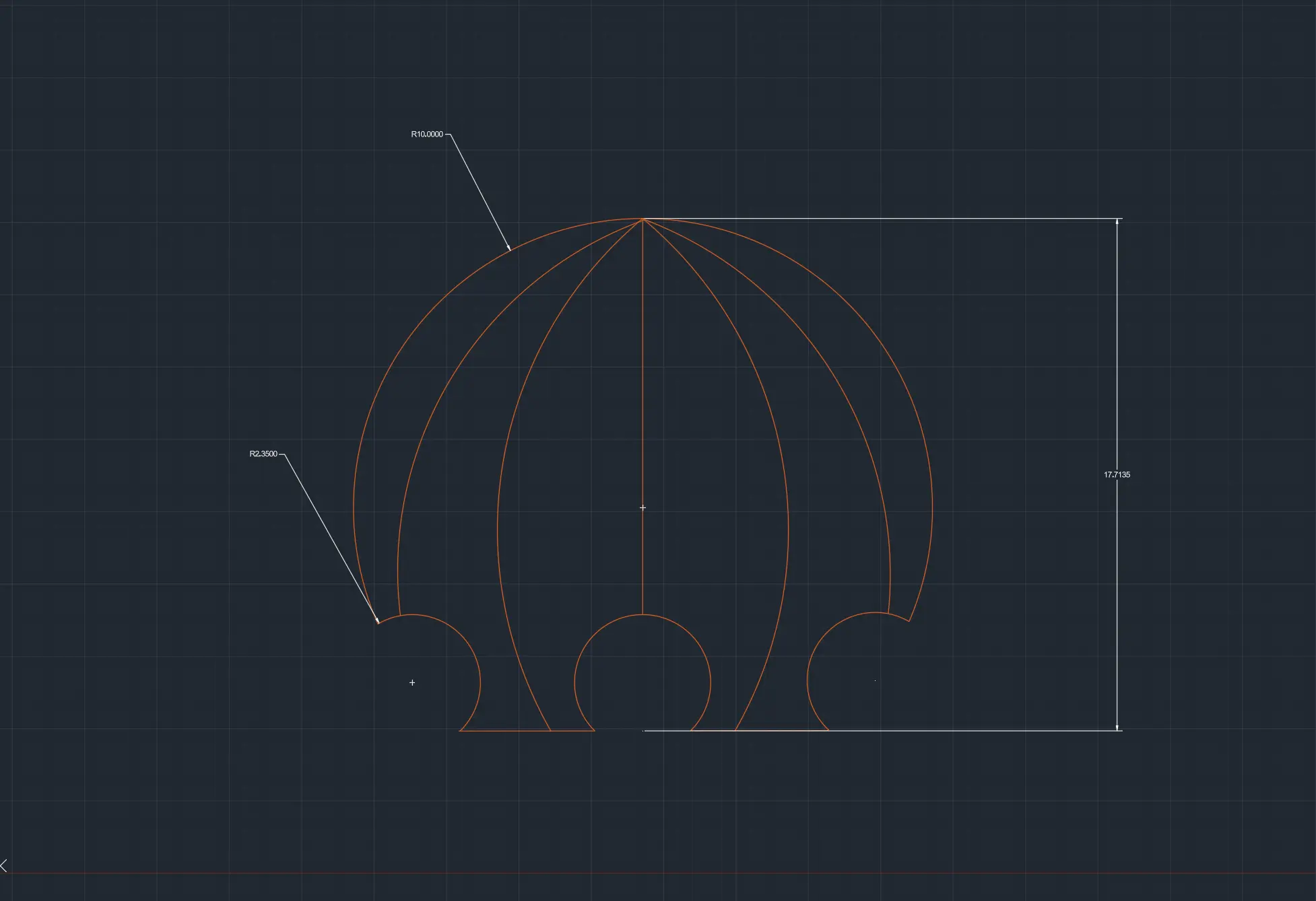
It´s important to note that AutoCAD also allows for 3D modeling (as you can see in some of the tools). For our purposes, we´ll only be using tools from the ''Drawing'' menu. With this shapes and lines, you can design your part´s 2D models, with exact notations and measurments. This 2D sketches of your pieces will help others understand and replicate your work. In my case, I used the most simple drawing tools to create this sketches of my final project´s pieces:
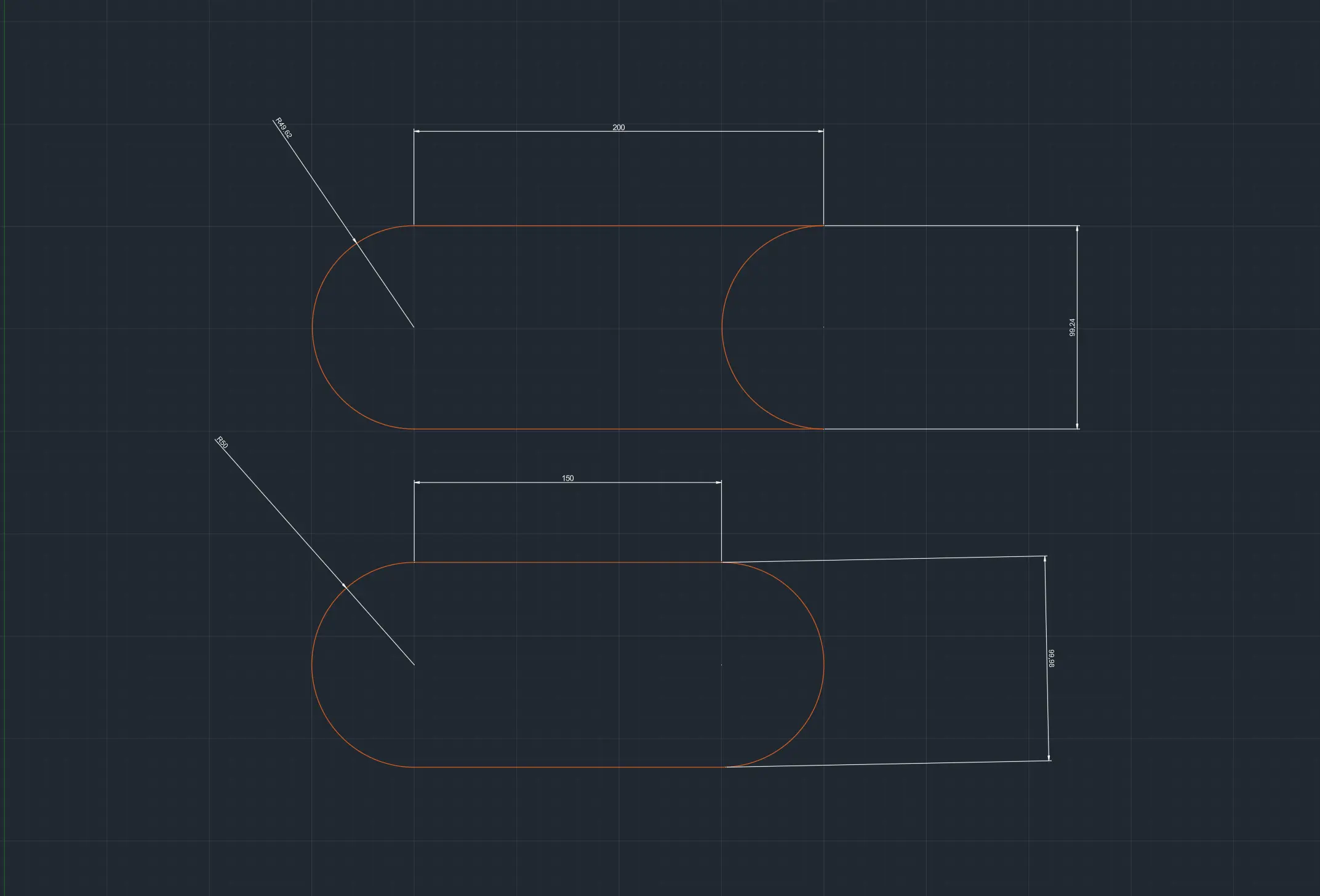
Sketching My Final Project
My project's 3D sketches will be build in OpenSCAD. Every OpenSCAD file created for project and all the FAB Academy can be found in my GitHub repository. If you take a look at my final project page in this portfolio, there is a extensive description on what my project is. For now you only need to know that we I design and Octopus shaped casing. This casing consists on two parts: The head and the tentacles.
The Tentacles
The first thing I started with was the tentacles, as I thought it was going to be the hardest thing to achieve. The tentacle consiste on individual links joined together by an articulation, in this case a chain like articulation. I decided to model 3 types of linking pieces: A base link that will be attached to the main casing, a linking joint meant to extend the length of the whole piece, and a tip link meant to close the tentacle.
The Base Link
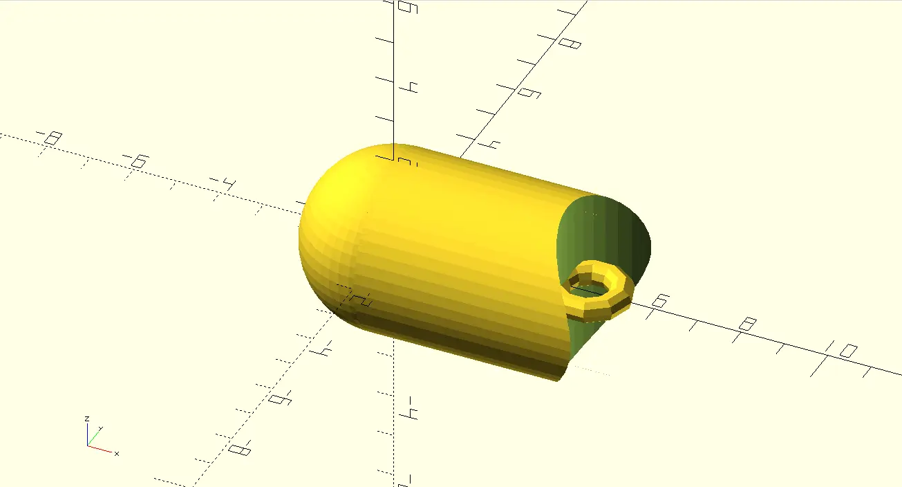
Making the base link required three simple shapes and some use of union() and difference(). The structure of the shape is:
Sphere + Cylinder (on it's side) - Cylinder (on it's side, rotated) = Base piece.
module base_joint(
              tentacle_diameter = 4,
              joint_lenght = 5,
              node_indentation = 4.5
          ) {
              $fn = 50;
                  union(){
                      // Body
                      union() {
                          difference() {
                              rotate([0, 90, 0])
                              cylinder(joint_lenght, d = tentacle_diameter);

                              translate([6.5, 0, -2])
                              cylinder(joint_lenght * 0.8, d = tentacle_diameter + 1);
                          }
                          sphere(d = tentacle_diameter);
                      }
                  }
              }

          base_joint();
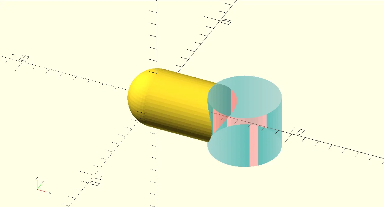
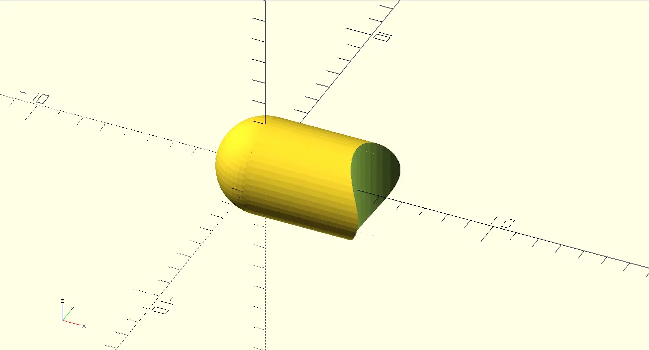
Here you can see the final shape. the blue piece is the deleted area from the second cylinder. The final piece looks like this:
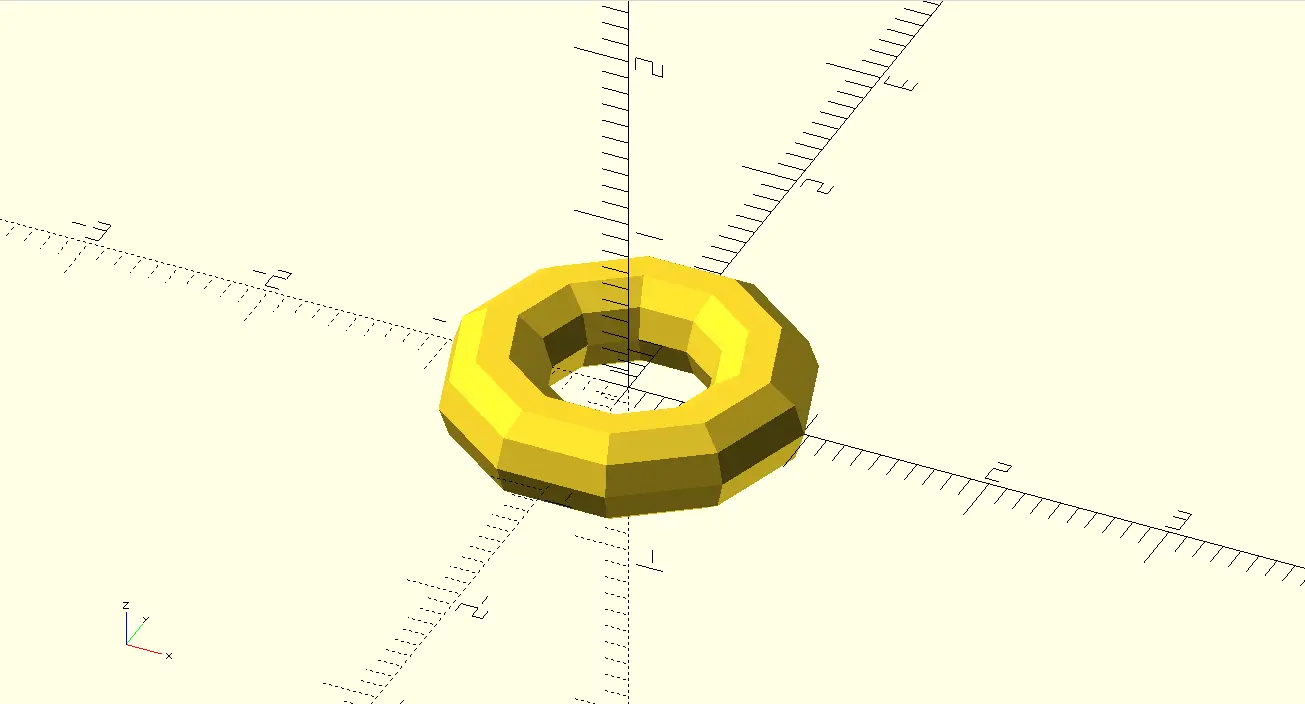
The Node
For our pieces to link, we need a node piece to work as the chain that holds our shapes.
module node(
              node_diameter = 0.7,
              node_thickness = 0.55,
          ) {
                  $fn = 10;
                  rotate_extrude() {
                      translate([node_diameter, 0, 0])
                      circle(d = node_thickness);
                  }
              }

          module_node();
Now, we can use this piece with the rest of our pieces. To do this, assuming both the node and every other piece file is in the same folder, go to your piece file and write use <FILE_NAME.scad> at the top of the file, changing "FILE_NAME" with your node file name. Now you can add some lines to your piece and get your node in place.
// Import //
          use <node.scad>

          // Visualization //
          base_joint();

          // Module(s) //
          module base_joint(
              tentacle_diameter = 4,
              joint_lenght = 5,
              node_indentation = 4.5
          ) {
              $fn = 50;
                  union(){
                      // Body
                      union() {
                          difference() {
                              rotate([0, 90, 0])
                              cylinder(joint_lenght, d = tentacle_diameter);

                              translate([6.5, 0, -2])
                              cylinder(joint_lenght * 0.8, d = tentacle_diameter + 1);
                          }
                          sphere(d = tentacle_diameter);
                      }

                      // Joint
                      translate([node_indentation, 0, 0])
                      node();
                  }
              }
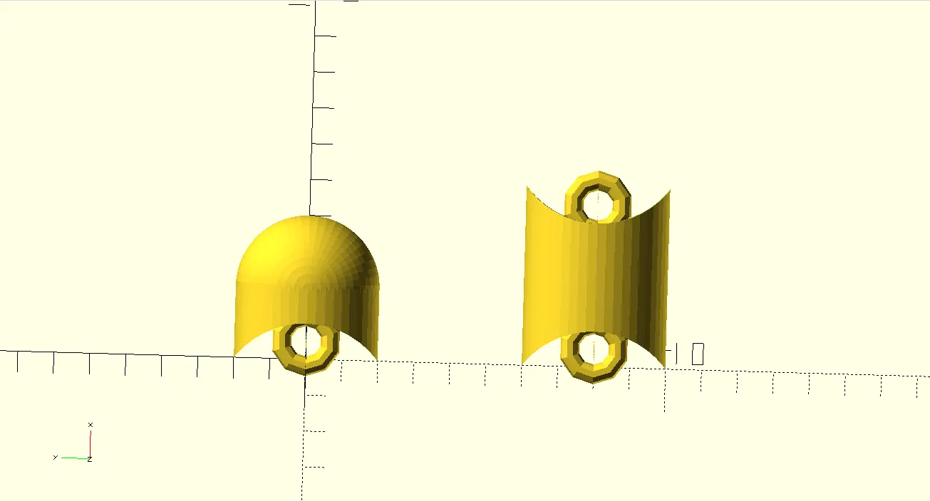
The Linking and Tip Pieces
Making the rest of the pieces is really straight forward now. The structure of the tip piece is the same as the base node, just with a smaller main cylinder.
The structure of the link piece is:
Cylinder (on it's side) - 2x Cylinder (on it's side, rotated, one on each side) + 2x nodes
The Beauty of Scripting
We now have our pieces and must join them. This can be as easy as importing them to a new master file, placing them down and translate() and rotate() each one to the desired spot, giving us a tentacle of n number of links. But what if we want to adjust the number of links? We can do it by adding more links and moving and rotating each one to their position.
But this is a programming language, and we can achieve this same effect automatically with the right logic.
Here´s what I did: The tentacle always starts by building a base piece. Then, with a for loop ranging from 1 to the desired length of the tentacle (passed as an argument to the tentacle module), linking pieces will be added, rotating them 90 degrees every other link. And finally, adding the tip piece to it all.
 // Tentacle creation
              rotate([90, 0, 0])
              base_joint();

              // Links creation
              for (i = [1:joints]) {
                  if (i % 2 == 0) {
                      rotate([90, 0, 0])
                      translate([joint_separation * i, 0, 0])
                      joint();
                  } else {
                      translate([joint_separation * i, 0, 0])
                      joint();
                  }
              }

              // Tip creation
              if ((joints + 1) % 2 == 0) {
                  rotate([90, 0, 0])
                  translate([joint_separation * (joints + 1), 0, 0])
                  tip_joint();
              } else {
                  translate([joint_separation * (joints + 1), 0, 0])
                  tip_joint();
              }
The Head
With the head I did something similar as with the tentacles. With a for loop and a sizes variable, I was able to rotate an n number of disks to form a sphere skeleton. And with a difference() I was able to get an n number of panels, that will be needed for the project´s casing.
module inner_layer() {
                  module side(z_rotation) {
                      rotate([0, 90, z_rotation])
                      circle(d = head_diameter + 2);
                  }
                  rotation = 360 / sides;

                  for (i = [1:sides - 1]) {
                      side(i * rotation);
                  }
              }
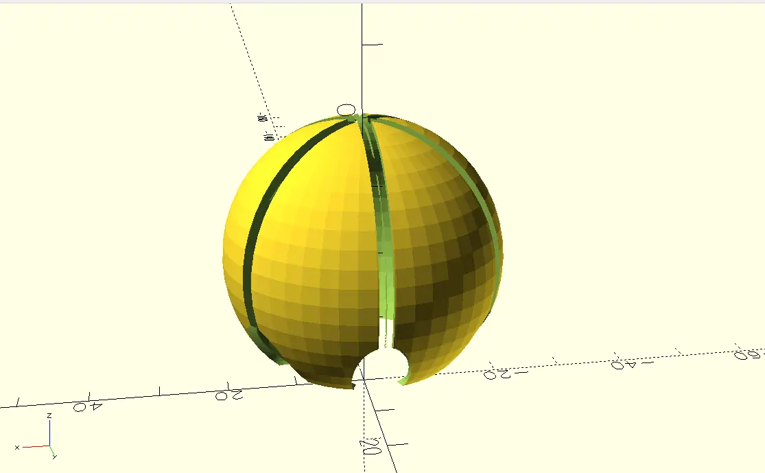
Using difference() again I was able to make some holds where the base of the tentacle will be.
The Final Model
Note: Rendering the project will take you a long time if you are using the stable download of OpenSCAD. If you are using the latest development snapshot, make sure you are using "Manifold" as your rendering setting, by going to Edit > Preferences > Advanced > 3D Rendering, and selecting "Manifold".
I imported the head and tentacle modules to a new file. For the head piece, i just placed it centered in the x and y axis. For the tentacles, I used another for loop to create one at every tentacle hole. And with that, the final model render looks like this:
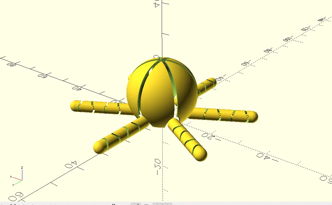
Image and Video Compression
As we progress throughout our FAB Academy journey, we´ll encounter a small issue regarding documentation: images and videos. All our work must be documented in a way, and both images and videos are the best at showing our work. However, images and videos are not optimal when talking about memory. The more quality the have the heavier the file will be. And when having multiple images and videos for each week´s worth amount of work, memory becomes and issue.
Image and video compression come in handy to solve our problems. Reducing image and video size helps reducing the overall memory needed to save it, at the cost of reducing their quality.
For images, changing the format from .png or .jpeg to something like .webp is more than enough to reduce it´s size and optimize it for web page deployment. For videos it becomes complicated, as video quality tends to suffer the most when compressing it. But converting a video to .gif can reduce it´s size enough.
Imagemagick
There are a lot of image compression tools online. ILoveIMG´s image compressorworks like a charm. For something more automated though, you can use a command line tool like ImageMagick. You can download ImageMagick´s executable file here. You can also install ImageMagick from your terminal with some package managers (in my case by running sudo zypper in imagemagick).
In Linux, assuming ImageMagick is already installed, navigate to your images’ folder in your terminal using the cd /Path/to/your/folder command. Then you can run mogrify -format webp *.png from your terminal:
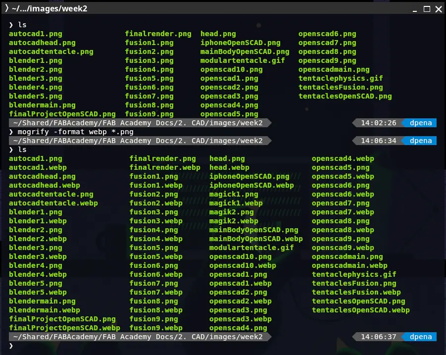
Mogrify will batch convert every .png image into a .webp image. This is usefull for me, as I use .webp as I explained before… If you only wish to convert a single image, you can also run magick image.png image.webp. This command will convert a single file to any other file you wish.
FFmpeg
FFmpeg is my main tool for converting videos into gifs. I prefer to use gifs instead of videos, as most of my videos are only there to highlight a specific moment of my work. This means my videos are short, a couple of seconds max. Gifs work best in this scenario, as they are best at showcasing short moments, like my videos. To convert videos into gifs, we can use FFmpeg, a suite of libraries for handling video audio and other kinds of media. To use FFmpeg, download it from their official Download page. For me, as explained before, I installed it with my Linux distro package manager by running sudo zypper in ffmpeg.
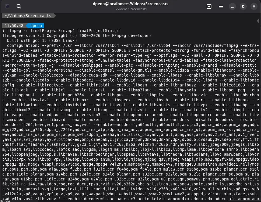
To use FFmpeg to convert a video to gif, simply run ffmpeg -i input.mp4 input.gif in your terminal. FFmpeg will automatically transform your video into a gif. The following image might look chaotic, but showcases (most of) the process FFmpeg takes in order to convert a video
Video Compression
However, there is a chance that a gif might still be too heavy to upload. In this case, you can add some modifiers to FFmpeg in order to achieve compression. Compression, in simple terms, is the process of reducing a file’s size by removing redundancy and encoding information. During the process of compression some information might be lost, which is reflected in the form of “lesser quality”. It is a trade off we need to take, as having a lesser quality video in our page is better than not having one because of its size.
To compress a video AND get it as a gif, we can run the following command:
ffmpeg -i input.mp4 \
          -c:v libx264 -crf 23 -preset medium -c:a aac -b:a 128k salida.mp4 \
          -vf "fps=10,scale=480:-1:flags=lanczos,split[s0][s1];[s0]palettegen[p];[s1][p]paletteuse" output.gif
If you wish to only compress your video without converting it into a gif, change the last line from output.gif to output.mp4.