Interface and Application Programming
Up to this point, our skills give us enough resources to bring projects to life, using micro-controllers, electronics productions, 3D printing, etc. But there is one big part of a project that we still haven’t tackled yet: interaction. There are some projects that need some sort of user interaction, whereas to get info, input info, control parts of the project, etc. For us engineers we can sometimes sin of thinking “If I can control it everyone should”. This is specially true with us programmers, where we can do a lot of things with a command line and think everyone can.
The harsh reality is that the general user of our project does not have the same amount of skills and understanding of our project as we do. Hence why we cannot expect a common user to interact with our project the way we could. For that, we need a sort of bridge between our project’s functionalities and our user.
This is were interfaces come in. An interface is a way of graphically showing anything we need to show from our project in one place. An interface can then allow us to input and output information from our project without ever needing to “peek under the hood”. Interfaces are designed with the final user in mind, as to give them an easier experience when using our product.
UI/UX
The UI/UX concept is an abbreviation of “User Interface / User Experience”. It refers to a series of practices that, when correctly applied, create a joyful experience for the user. UI/UX is a whole world of knowledge, often requiring dedicated courses to grasp. My girlfriend, for example, studies “Animation & Interactive Design”. Half of her courses are dedicated on the study of how user interact with products. Designing and executing a good UI/UX for our project requires market studying, user understanding, age range, etc.
This is why we are not planning on completely understanding the ways on UI/UX, specially for this week time frame. We just need to keep one key principle in mind: the final user needs to see our interface and understand it. If we can get an external user, with no information on how our project works, to use our interface correctly: we win.
Getting Started
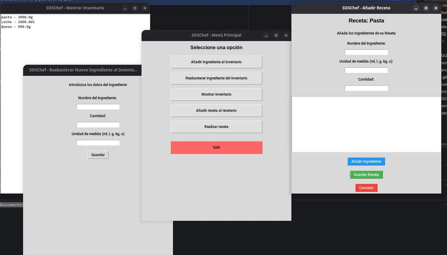
There are a lot of tools available to us. Some of these tools, like React Native, are amazing for web and even phone applications. Although for apps you might want to take a look at swift + Xtools for iOS apps and Kotlin for Android apps. Personally, I’ve dealt with React before for web development, and for more desktop oriented development I’ve dealt with Tkinter before, which is a UI toolkit for python. With Tkinter I’ve built a restaurant storage administration app I called “SOSChef”:
I could perfectly use Tkinter for this week’s work, but I’d rather go with another option our instructor Rafa taught us: PyQT.
PyQt
PyQt is the python integration of the Qt GUI toolkit. Qt simplifies the GUI development process, as it includes a “widget” oriented design tool. This means that designing your GUI is as straight forward as using Figma for web. But unlike Figma, this designs are directly translated into code. Here’s where an interesting question arises: Why PyQt and not Tkinter?
For starter, I want to expand my development toolkit and learn a new tool, that being PyQt. Second of all, PyQt’s widget to code system will allow me a faster development experience than with Tkinter, where everything must be placed by code. This doesn mean that PyQt is perfect though, as its huge amount of tools and concepts make it harder to master. This amount of tools, however, also give it its “industry standard” badge. Here is a small comparison table I’ve made:
| Tkinter | PyQt | |
|---|---|---|
| Design style | Manual | Visual |
| Widgets | Limited to basic components | Extended catalogue of components for different tasks |
| Styling | ttk | QSS (basically css) |
| Arquitecture | Procedual (functions) | Object Oriented Programming (classes) |
| Weight | Lightweight | Heavy |
| Licence | Free (MIT) | Commercial (Requires payment for closed projects) |
My personal recommendation is to use Tkinter for personal and small hobbyist projects, and PyQt for more serious applications. For more information on PyQt and some other interface programming platforms (like Tkinter), check out our Lab’s week group assignment page. This page includes a quick guide on how to use PyQt and Tkinter. In a moment I will be showcasing how to create a new PyQt project from scratch, but if you decide Tkinter fits your project’s necessities better, the tutorial on this group assignment page is a great starting point. Plus, you will also learn LabVIEW, a platform designed for embedded platforms such as Arduino and Raspberry Pi.
The Python Development Environment
We will be working with Python right now. Python is a powerful, easy to understand and learn, general purpose programming language. We’ve used python before in the shape of micropython. In the world of embedded programming, python (micropython) is often seen as a “learning tool” meant for prototyping and not serious applications because of its heavy weight and slow operation times when compared with C. In other applications, when operation speed is not the main metric to measure, python dominates, being the leading programming language for data science and machine learning and artificial intelligence development. Python’s syntax is pretty similar to English, so for big code bases with complex logic, python is great. Needles to say, python is my favorite programming language.
To start developing in python, we first need to be sure it is installed in our system. Python can be download from its official download page (this is the easiest method for Windows and Mac users) or via the command line. Once python is installed, we can start writing code and running it with out any issue. However, for projects that require external libraries, like PyQt, we need to create a development environment.
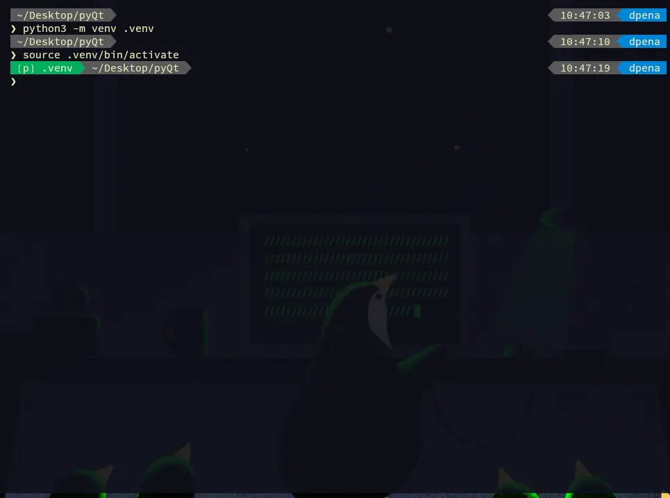
To do this first create your project’s folder. In your terminal, navigate into it by typing cd followed by the path to your folder, and write the following command (assuming you have Mac or Linux): python3 -m venv venv. This command will create a Virtual Environment.
Virtual Environments
Virtual environments are a way of isolating our projects dependencies into its own folders. In the past, we would install all those libraries into our own laptop. Now, libraries are installed independently into our project, which means that they can be erased with our project without leaving a trace of it in our system. For this reason, Virtual Environments are the best practice when developing in python.
We created our Virtual Environment folder, called “venv”. You can technically rename your folder to anything you want, by changing the second “venv” in the previous command to anything you want. But it is a convention to name your Virtual Environment either “venv” or “.venv” (if you want the folder to be hidden), so stick with those. Now we need to activate our virtual environment. Again, assuming you have a Mac or Linux device, run the following command: source venv/bin/activate. Your terminal should get a “(venv)” indicator. You are now inside your python Virtual Environment.
Note: NEVER modify anything inside your venv folder. You must not enter this folder whatsoever.
The next step is to install anything we need for our project. To do this, we will be using pip, the python package manager. Go back to your terminal, in your project’s folder path, and type pip install --upgrade pip to get the latest pip version. This is not mandatory, but it is a good practice. Now, run pip install <package-name> to install a package. For our project, will be installing PyQt by running pip install pyqt6. Pip will automatically install our package.
If at anytime we want to know our installed packages, we can run pip freeze to get a list of them. Even better, you can run pip freeze > requirements.txt to put those packages names in a text file. Whenever you finish a project you are willing to share with the world, creating this “requirements.txt” file is a mandatory step, as the public needs to know which packages to install to run your project.
With PyQt already installed, we are ready to go to the next step!
Qt Creator
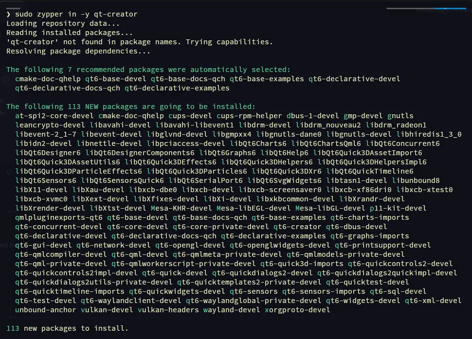
As explained before, Qt offers a variety of development tools, one of which being the drag and drop widget designer. This tool is conveniently named “Qt Designer”. If you are on Windows or Mac, you can download Qt Designer from it official download page. For us Linux users, it is best to install Qt Creator, a whole Qt development platform which includes Qt Designer. Think of it like KiCAD, a software that is actually a combination of more software. I personally installed Qt Designer by running sudo zypper in qt-creator.
Once installed, open the Qt Creator app.
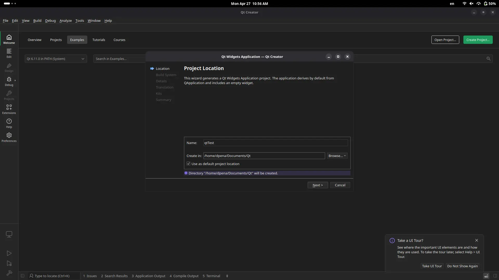
Click “Create project”. You’ll be asked what type of project you want to create. Select the “widget application” option. Now we can specify our projects location. Create a project location, and click “Accept” to everything else. Once this is done, will be prompted into our main working space.
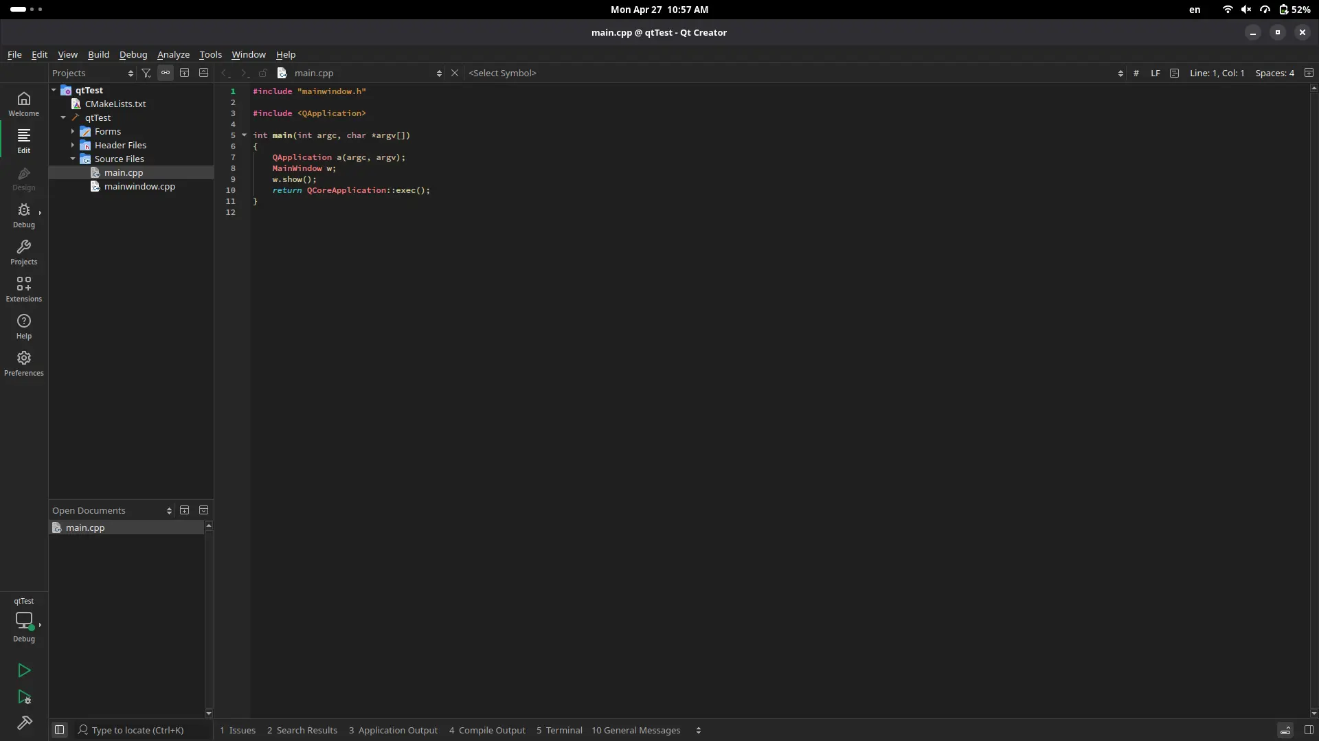
This workspace includes multiple C files. We are not interested in those. In your file tree, navigate to “Forms”. there should be a file with an .ui extension. Click it to open it.
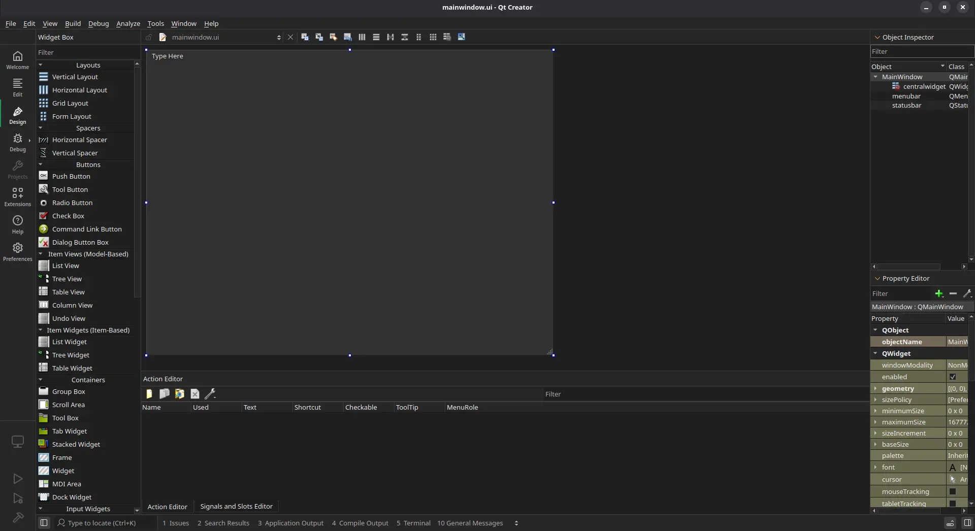
Here is our Qt Designer tool. A quick run down of what we are looking at:
- On your left there is a side menu with all the available components you can use.
- In the center, there is your main working area. This working area will also be the shape of you application.
- On your right there is a component list listing everything you have added into your page. Plus, a property editor to modify individual characteristics of your components.
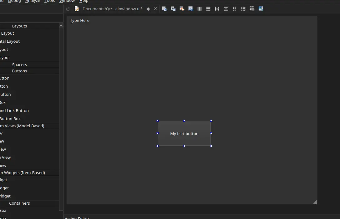
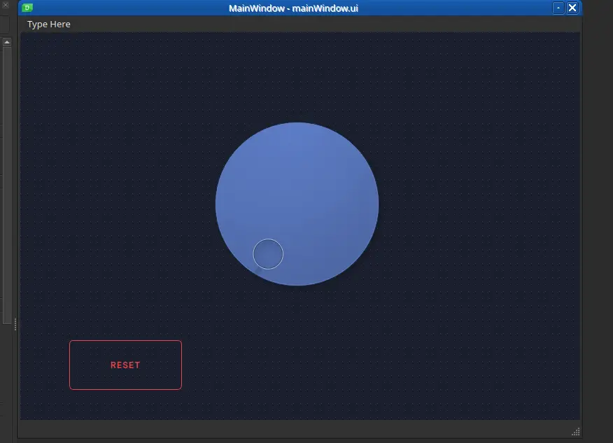
To add a component, like a push button, simply drag and drop it! Double tap on the button’s text to change it.
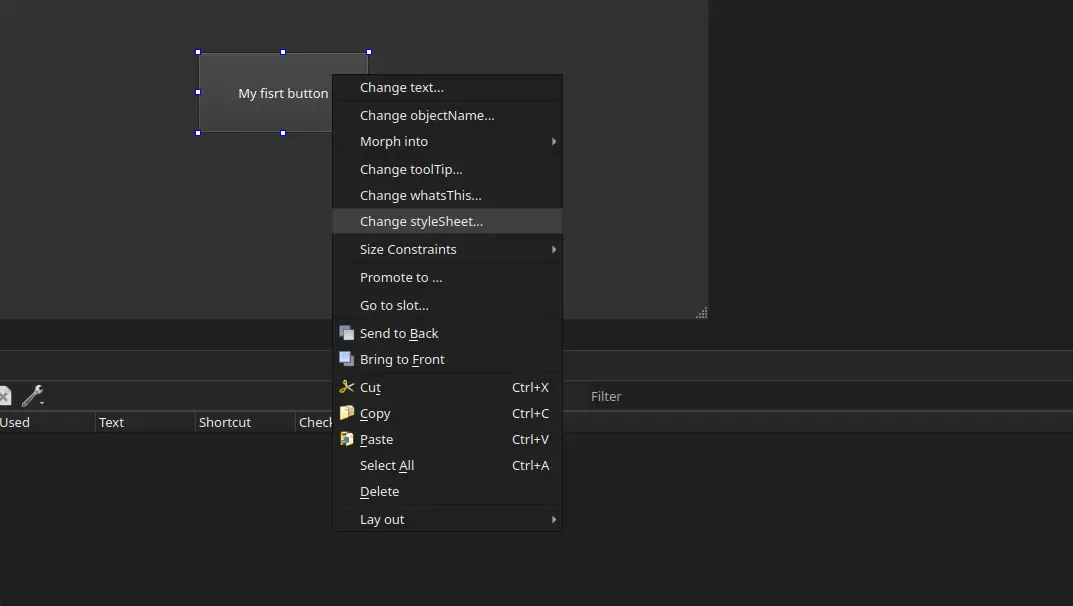
Our button has no style, yet. If we wish to add style into it, we can easily modify it by using QSS, a modified CSS for Qt. To do this, right click into your component and select “Change Stylesheet”.
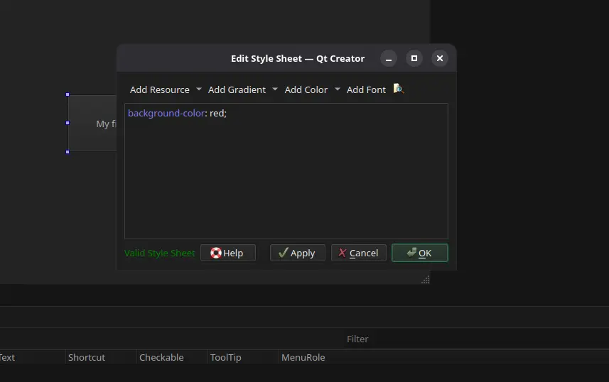
A text box will appear. Introduce your desired CSS instructions. In my case I changed the button background to red.
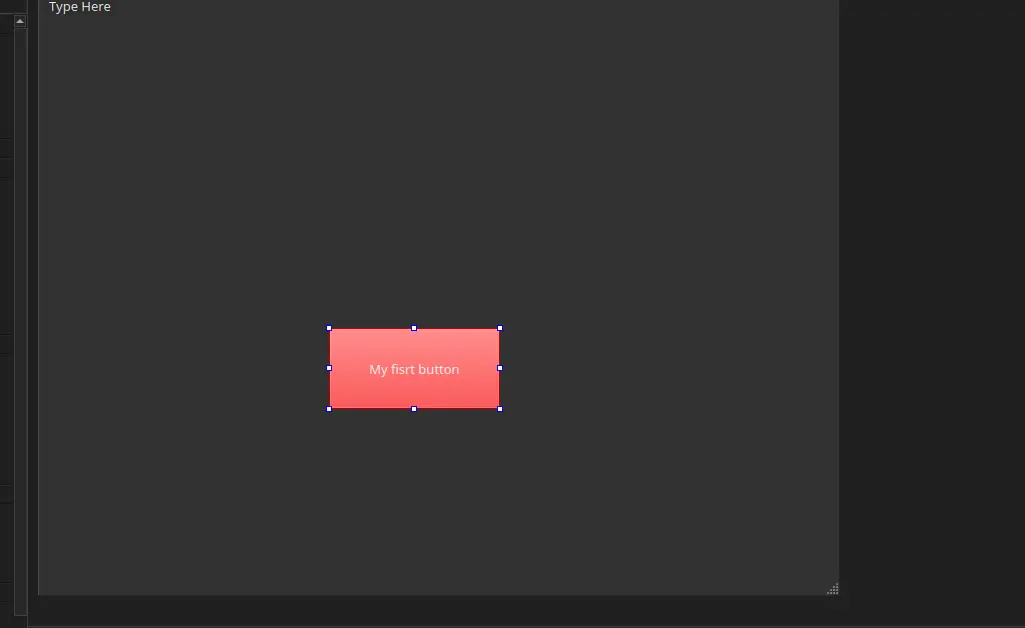
Now hit “Apply” and then “Ok”. our button is now red!
Now, the sky is the limit. You can combine as many or as few components as you need, with as many or as few style changes as you want.
Transforming ui Into Python
We now have a .ui file to work with. Navigate to the “Edit” tab on your leftmost side menu (the one with the horizontal lines). Here is the code version of your UI. It might look like HTML, but it is not. It is actually XML, a programming language older than HTML! This .ui file is now ready to export to use in our python project. To do this go to File > Save “path/to/your/mainWindow.ui” as. Save the file into our python project file.
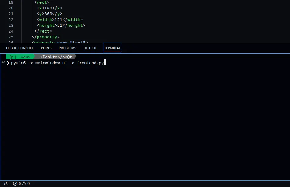
Now, we need to convert this XML file into Python code. To do this, we first need to install our converting library by running pip install pyuic6. Now, simply run pyuic6 -x <your-file.ui> -o frontend.py. A new file called “frontend.py” will appear on your folder.
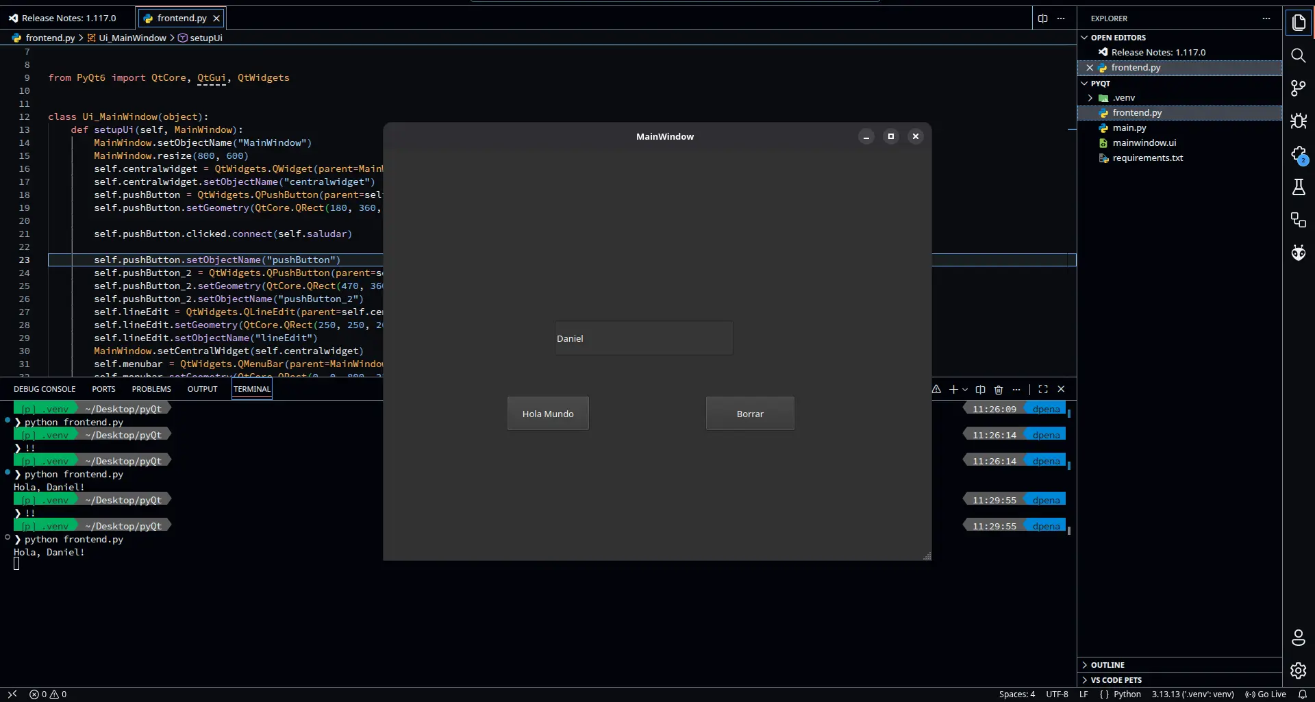
Now we can run our app to preview and use it. To do this, simply run python frontend.py in your terminal. Your app will appear as a window!
The Backend
We now have the “frontend” or the interface part of the app. Now we need the “backend”, the part “under the hood” that controls our UI and connects with our micro-controllers. The connection between frontend and backend is what creates an app. To start building our backend, create a “backend.py” file in your project. It doesn’t have to be named like than, you can name it whatever you want. I personally name my main scripts like “main.py”.
Your base code in your backend file should look like this:
from frontend import *

        class MainWindow(QtWidgets.QMainWindow, Ui_MainWindow):
            def __init__(self, *args, **kwargs):
                QtWidgets.QMainWindow.__init__(self, *args, **kwargs)
                self.setupUi(self)


        if __name__ == "__main__":
            app = QtWidgets.QApplication([])
            window = MainWindow()
            window.show()
            app.exec()
This code firstly import our frontend file. Then, we create an object for our Window. In this section we will be able to give extra functionality to our components (more on that later). The last part is just a standard protocol code that tells the file when directly calling its running. This prevents other files to accidentally run this code.
Now, we can run python backend.py to run our app. Whenever we make modifications to our frontend.py file, it won’t affect our backend file.
Adding Functionality
In our backend file, we can attach extra functionality to our UI components. This functionality can be anything we want. To do this, we can create a function like this one:
def get_position(self, dial):
               value =  self.dial.value()
               print(value)
Note: every function we write must be inside the main Class, and should always have the “self” argument.
This function takes the value generated from our dial and prints it into our terminal. To attach this function to our dial, we can simply add this line in our “init” function (the first one of the class):
self.dial.valueChanged.connect(self.get_position)
With this code, we are telling the dial to call the get_position function whenever its value changes. There are a ton of conditions we can use. For example, if we wanted to detect a button press, we could simply add:
self.button.clicked.connect(self.button_press)
Now, whenever we run our app, the functionality will be added to the components by itself!
Connecting to the Micro-controller
We are now going to connect our micro-controller to our UI. For this, we will be using a Serial port (USB). Connecting python to a serial devices requires an extra library. We can install it by running pip install pyserial in our terminal. Using serial with python requires some understanding of how this connections work. Luckily for us, our instructor Rafa prepared us a GitHub repo with a base example on how to use pyserial. For our use case, we will be using his base_serial.py script as is.
The Movement Script
Our micro-controller will be needing its own script two receive the data from the dial and move the motor accordingly. In the base_serial.py script it is explained that messages are received with Serial.readStringUntil('\\n'). But this is written in Arduino, and I want to use micropython for this week. The syntax changes, but the idea is the same:
import select

        # Serial Port Config
        poll_obj = select.poll()
        poll_obj.register(sys.stdin, select.POLLIN)

        while True:
        	# Checks for data in the serial buffer
        	poll_results = poll_obj.poll(0)

        	if poll_results:
        		# Reads incomming message
        		mensaje = sys.stdin.readline().strip()
Here, our one line of Arduino code is converted into multiple steps (weird, it is usually the other way around). We begin by connecting to our serial port. This connection is done by default. Then, in a loop, we check for data in the serial buffer. If there is something in the serial buffer, we grab it and save it as a variable in our program. Then we can do whatever we want with our message. As our value is an integer, we can transform it into one:
if mensaje:
        	try:
        		# Convert message to string
        		dial_value = int(message)

        	except ValueError:
        		# Ingore unrecognized values
        		pass
The try: statement is another type of flow control. It basically runs whatever code its inside of it until something goes wrong. If something goes wrong, instead of stopping the program completely, we can tell it what to do in the exepct: segment, which is mandatory to have with try blocks. We use the try whenever we know “something” will go wrong at some point. In our case, the except line catches a “ValueError”, or the error that would pop up if we tried to convert an invalid message into an integer, like a letter or an unrecognized character. Adding this ensures our code will continue to flow even when receiving invalid messages.
Now, we need to map our values to get the relationship between the dial values and the stepper motor values. The dial can take am integer value between 0 and 99, whilst the stepper motor can take a value between 0 and 200, in both cases considering a full turn. Our zeros will always be the same, but a 10 on the dial will not translate into a 10 in the stepper. We need to fin that ratio. Arduino already has this function built-in with the map() function. We simply give it our value to calculate, min and max of the first range, min and max of the second range. In Arduino, this code would look like this map(value, 0, 99, 0, 200). But we are using micropython right now, and micropython has no function similar to this one. Python actually has a “map” function, it just doesn’t work the same. We need to create our own mapping function. Thanks to Gemini AI, we can get this pretty easily:
def map_valor(x, in_min, in_max, out_min, out_max):
            x = max(min(x, in_max), in_min)
            return (x - in_min) * (out_max - out_min) // (in_max - in_min)
The “X” variable is called “Clamping”. It is there to ensure our mapped values won’t go over the limits. Then, (X - in_min) is a normalization value we need to multiply by our scaling (out_max - out_min) // (in_max - in_min). The “//” is just a division where we get only an integer as a result, no decimals.
With our mapping ready, we can use this function as we would the map() function on Arduino. The last step required is the actual stepping of the motors. The logic is as follows: We get our target values. If its less than our current position, we take a single step into that direction. If it is more, we take a single step into the other direction. If it is the same, we do nothing. All of this is in a loop, so we will take the necessary amount of single steps until we reach our position. Then, our target position becomes our current position:
if target_steps > current_pos:
        	dir_pin.value(1)
        	step_pin.value(1)
        	time.sleep_us(800)
        	step_pin.value(0)
        	time.sleep_us(800)
        	current_pos += 1

        elif target_steps < current_pos:
        	dir_pin.value(0)
        	step_pin.value(1)
        	time.sleep_us(800)
        	step_pin.value(0)
        	time.sleep_us(800)
        	current_pos -= 1
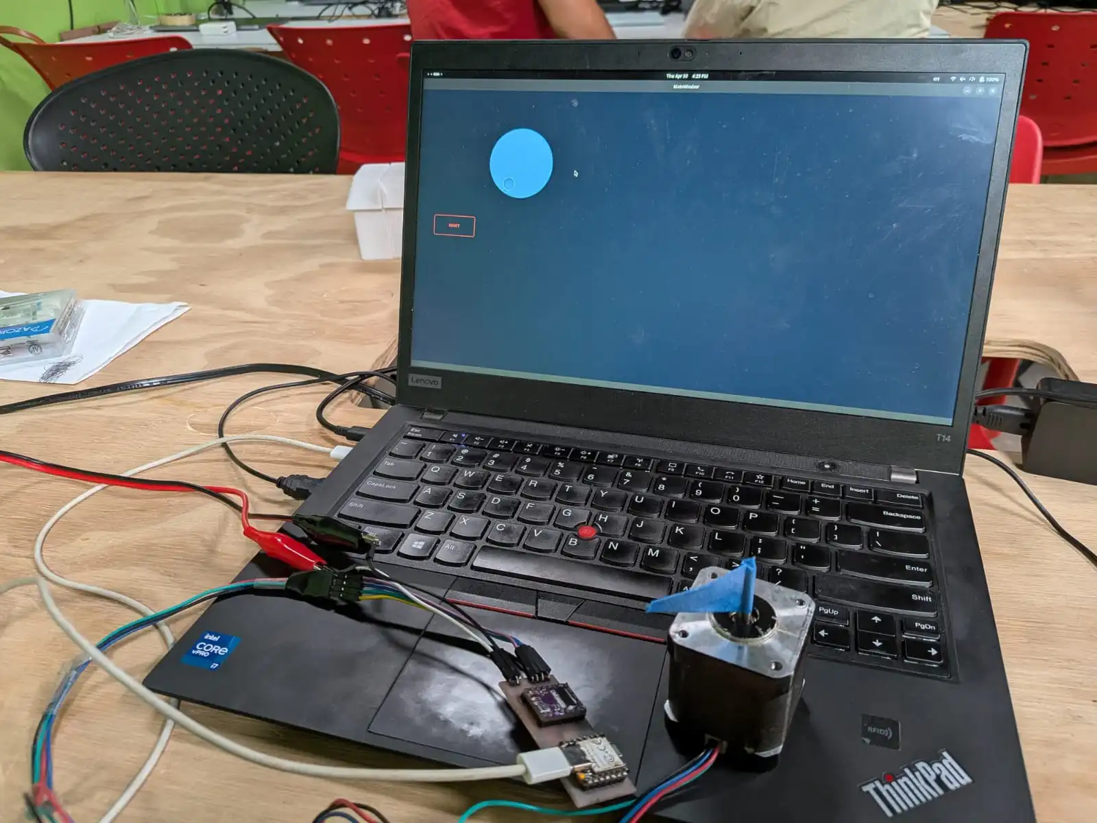
Interfacing With The Stepper
With our interface ready, our stepper motor connected and our RP2350 script flashed, we can start controlling our stepper the process is as simple as connecting the RP2350 to my laptop with a USB-C to USB-C cable. The laptop will automatically assign it the “/dev/ttyACM0” port. Now, we just run our backend script by typing python backend.py into our terminal. Our UI will appear on screen. And if we move the dial, the motor moves with it!
As you can see, dragging the dial will make the stepper motor mimic that movement to a tee. Clicking anywhere on the dial will make it automatically change its position to it, causing the stepper motor to snap into that position. And at last, clicking on the “Reset” button will cause the stepper motor to return to its zero position. This is possible because the reset button sends a “0” message.
What About Receiving Data?
My current setup does not include any useful input device to send data into my UI. This does not mean that I skipped this part. Even without a sensor to send data from, we can still send something into UI. With micropython, the process is really easy. To easy, in fact, that even the print() function, the most basic function in python, can send data to the UI. Our Serial Worker’s _leer() function ( Spanish for “read”) is told to receive any data up until “\n”, or a line break. Python’s print() already includes an “\n” at the end of all messages.
Making It Pretty
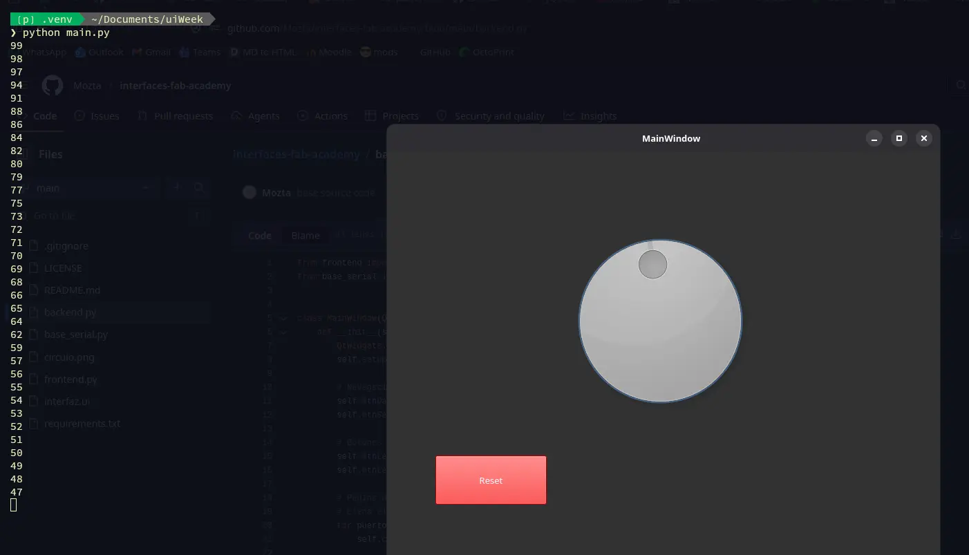
The last step in UX/UI designing, at least for me as a programmer first, is to give our interface style. To be really honest, this is the step I dislike the most, specially in Web Development. I’m just not into the whole design world. Luckily for me, AI is pretty great at giving styles to web pages. This skills should also translate to QDesign styling, as QSS is basically just CSS. You can try and ask your favorite AI agent for a QSS design sytlesheet for your components. This can be specially useful when dealing with a big number of components per window, or a unified design that your UI needs to follow. For me, I tried m y best to give my simple two component UI some style:
And with that, our UI is ready and funcitoning!
Bonus! Person Tracking
One of the objectives of my final project is to track persons using a Xiao Sense camera module. This way, my Octo-Robot can adjust its base position to always face the person its talking to. Now, during this week I already figured out a way of sending coordinates to a micro-controller, for it to send to the stepper motor. This is the one aspect I needed to figure out before trying to implement the person tracking. So here I am, with stepper motor, a driver + micro-controller PCB, and a way to send signal through serial from my laptop. Let’s get into it then.
The first thing, and probably the most important thing to get right, is the person tracking aspect of the project. As I said before, I plan on using a Xiao Sense camera module, for its small size and big capabilities. For now, I will be using another way of person tracking: OpenCV.
OpenCV
OpenCV is a library of multiple functions, all targeted to machine vision. OpenCV gives “eyes” to our devices, allowing them to understand what they are capturing and act accordingly. There are a lot of things you can do with OpenCV, and one of them is person tracking. OpenCV makes the person tracking process as easy as adding some lines of code. Spoiler alert, but the whole script running this final result is under 60 lines of code! This is posible because of OpenCV’s default models already prebuilt within it. There are models for person tracking, hand gestures, etc. The possibilities of OpenCV are massive, and I really recommend diving into it if you are interested on machine vision.
For this project, I will be using this example code by Jan on Nulldog. The code is quite simple. It begins a transmission on your web cam (you can adjust this if you have an external camera). Then, using the default person tracking model, starts tracking a person, drawing a bounding box. Finally, the bounding box is adjusted depending on the person movement.
What we are really interested on is the bounding box. To draw a bounding box, we need an x and y position, and a width and height. The bounding box is then drawn as so: first point is (x,y), second point is (x + width,y), third point is (x, y + height), fourth point is (x + width, y + height).
These points are important to us, as we can use them as values to send to our micro-controller. If we take x and x + width and divide by 2, we can the horizontal center line of our bounding box. This way, when our micro-controller receives that value it will adjust towards “us”, or more precisely the center of the bounding box put on us.
So, with a small modification, our code looks like this:
import cv2
        from base_serial import SerialWorker

        # Import the seria Worker
        serial = SerialWorker()
        serial.conectar("/dev/ttyACM0")

        # Loads the default people detection model
        hog = cv2.HOGDescriptor()
        hog.setSVMDetector(cv2.HOGDescriptor.getDefaultPeopleDetector())

        # Capture video on Webcam (default)
        video_capture = cv2.VideoCapture(0)
        tracker = None

        while True:
        	ret, frame = video_capture.read()
        	if not ret: break

        	# Size of the video frame
        	frame = cv2.resize(frame, (640, 480))

        	# Creates the tracking bounding box on the person
        	if tracker is None:
        		(rects, weights) = hog.detectMultiScale(frame, winStride=(4, 4), padding=(8, 8), scale=1.05)

        		for (x, y, w, h) in rects:
        			try:
        				# Assigns a tracker to the person
        				tracker = cv2.TrackerCSRT_create()
        			except AttributeError:
        				tracker = cv2.legacy.TrackerCSRT_create()

        			tracker.init(frame, (x, y, w, h))
        			break # Tracking only the first detected person

        	# Updates position of the bounding box as the person moves
        	if tracker is not None:
        		(success, box) = tracker.update(frame)

        		if success:
        			(x, y, w, h) = [int(v) for v in box]
        			cv2.rectangle(frame, (x, y), (x + w, y + h), (255, 0, 0), 2)

        			# Calculates the center of the image
        			centro_x = x + (w // 2)

        		 	# Sending the value to the RP2350
        			serial.send(str(centro_x))

        		else:
        			# Re track if the person is lost
        			tracker = None

        	cv2.imshow('Tracking for Stepper Motor', frame)
        	if cv2.waitKey(1) & 0xFF == ord('q'):
        		break

        video_capture.release()
        cv2.destroyAllWindows()
The comments on the code should be enough to explain the overall functioning of it. And on the micropython script we only need to add a couple of changes:
- Added a “Noise filter”, to only process whole numbers, as to not confuse our mapping function with floating numbers.
- Changed the mapping values, to only work on half of the stepper motor range (100) and to work with the OpenCV frame resolution (640).
- Reduced the sleeping values between each step of the stepper motor, for a better tracking feeling.
The process of running this tracking script (tracking.py from now on) is the same as with our backend script. We only write python tracking.py in our terminal. OpenCV will automatically create a window to see our tricking live. This window might not have the best resolution, freezing a little between frames. But in reality the video is being processed correctly. Now we just need to connect our RP2350 to our “/dev/ttyACM0” port (default port when connected to my USB-C port), and done! Surprisingly, as we already coded a functioning movement script, the whole project worked first time!
What Comes Next?
The script that will handle this movement on our final project will be pretty much the same (if not translated into C if speed becomes an issue). The only extra thing will be adding the Xiao Sense into the mix, and solving the bridge that will exist between the Xiao Sense -> Raspberry Pi 5 -> esp32s3. Everything else should work as is. The logic stays the same: we get the horizontal average from the data received from the Xiao Sense, and use that in our movement script.
The Bottom Line
I know that will my skill set I could have done something more impressive for this week’s work. But I kind of suffered from the “blank canvas” syndrome, where not knowing what to do freezes an artist. The reality is that my final project does not require a user interface, as the project itself is a user interface (Machine-Person Interaction). This doesn’t mean that the things I learned this week won’t be useful for my future projects and even my career. PyQt6 is now officially part of my tool box, expanding my capabilities as a Software Developer. And, whenever I start working on a project that requires interfacing with a micro-controller, I would know how to. This week was a complete success!