Group Assignment Focus
This week's assignment was to design a machine that includes mechanisms, actuation, automation, and application, as well as to build the mechanical parts and operate it manually.
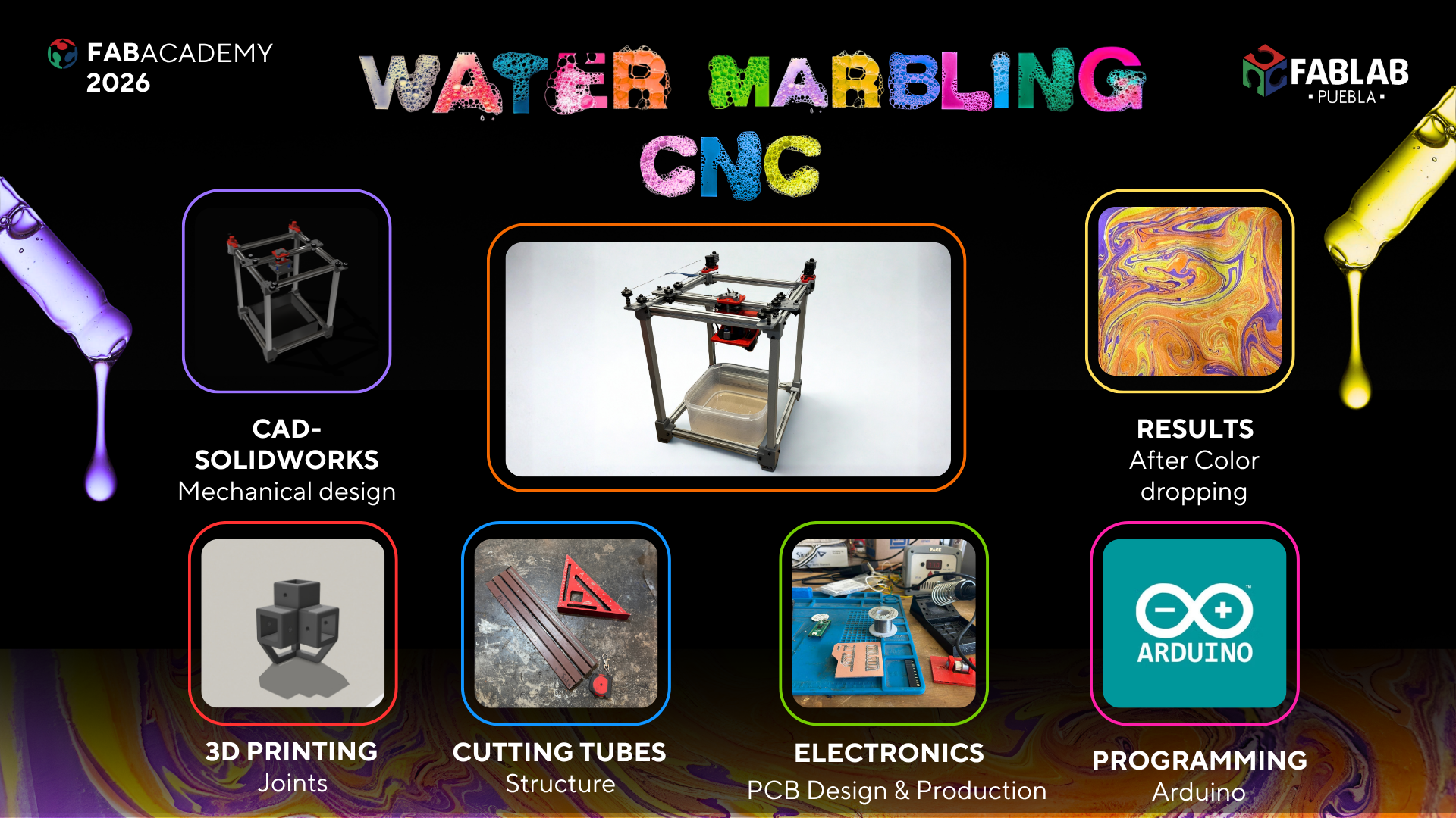
Our Project: Water Marbling CNC
We decided to build a CNC machine specialized in Water Marbling. This technique involves dropping paint onto the surface of thickened water to create patterns, which are then transferred to paper or fabric. Our machine automates the drop placement and the "combing" process to create consistent, complex geometric patterns.
The Team
| Member | Core Contribution | Portfolio |
|---|---|---|
| Selene Roman | Structural design, mechanical movement assembly, and interface development. | Individual Contribution |
| Kamil Gallardo | Electronics, programming, and motion testing. | Individual Contribution |
| Ana Tellez | Testing and calibration of the silk painting process. | Individual Contribution |
| Carlos Perez | Structural assembly, and Color switch logic design. | Individual Contribution |
Fabrication & Building Process
2D Axis - Mechanical Movement Development
The mechanical motion of our machine is based on the Urumbu 3D concept, adapted to our specific requirements. The design features a 2-axis motion system and a custom toolhead to house the color switching mechanism. We fully integrated the dual-axis movement logic from the Urumbu 2022 and Urumbu ULB architectures. The dual-axis system consists of a support tube parallel to the work surface. This tube houses an X-axis rail that slides internally, while the entire tube assembly moves across the workspace via two Y-axis rails. The combinated movement of these three rails allows the XY movement.
The stepper motors are mounted to the corners of the tubes, using a string-drive system to move the carriage in the desired direction.
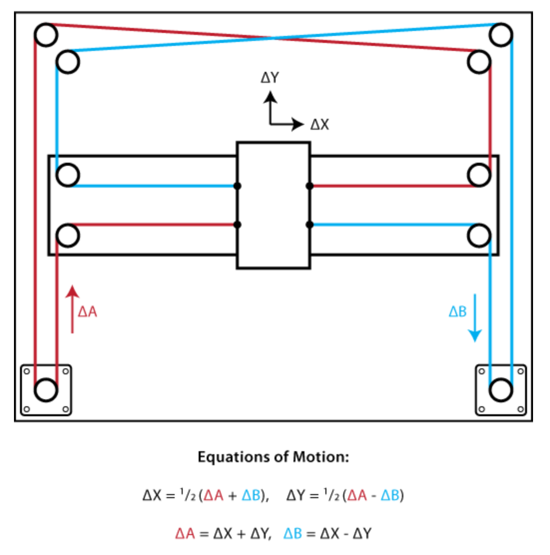
The motion principle of our machine follows the CoreXY movement system. CoreXY is a kinematic motion architecture where two fixed stepper motors collaborate through a cross-belt system to displace a toolhead across the Cartesian plane. Its operating principle is based on the addition and subtraction of motion vectors: synchronous rotation of both motors in the same direction produces displacement along the X-axis, while counter-rotation generates movement along the Y-axis. By keeping the motors static on the chassis, the inertial mass of the mobile system is drastically reduced, allowing for higher accelerations and operating speeds with minimal structural vibration.
Materials and Manufacturing
T-slotted aluminum framing rails were used as the primary components for the machine's chassis. The remaining mechanical parts were 3D printed, including original designs as well as files retrieved from the UrumbotXY-Fall2022 repository. Select files from the repository were modified based on testing results to better suit our project's needs.
| Quantity | Material |
|---|---|
| 8 | T-slotted aluminum framing rails |
| 4 | Perfil Tubular Rectangular |
| 28 | M4 Screws |
| 21 | M5 Screws |
| 12 | M3 Screws |
| 2 | M8 Screws |
| 9 | Type V Delrin Wheels |
| 8 | Dual V-Type Delrin Wheels |
| 4 | Bearings |
| 4 | Meters of Kevlar string |
Modules
The initial step involved assembling all the modules responsible for the XY movement system.
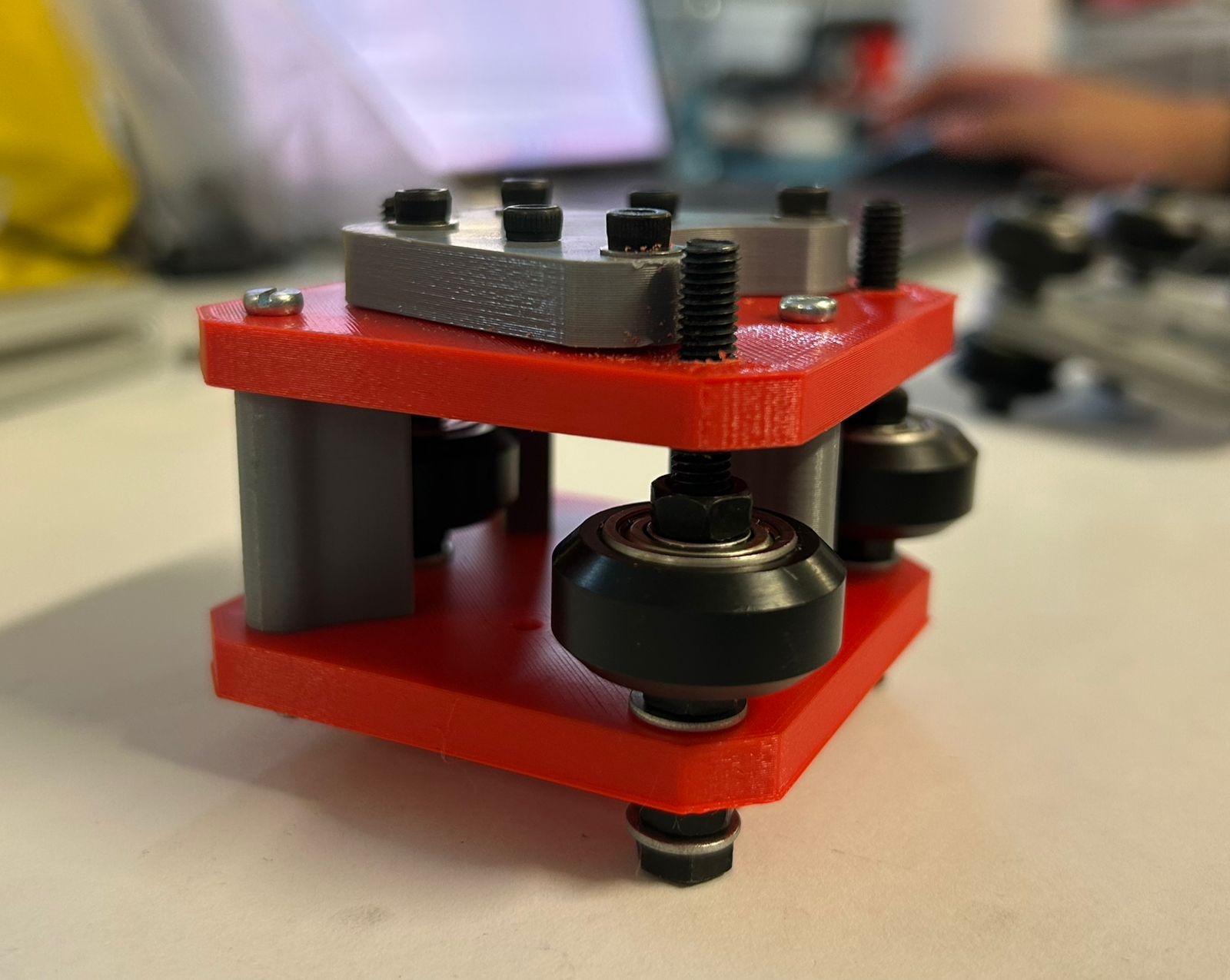
Y-Plates
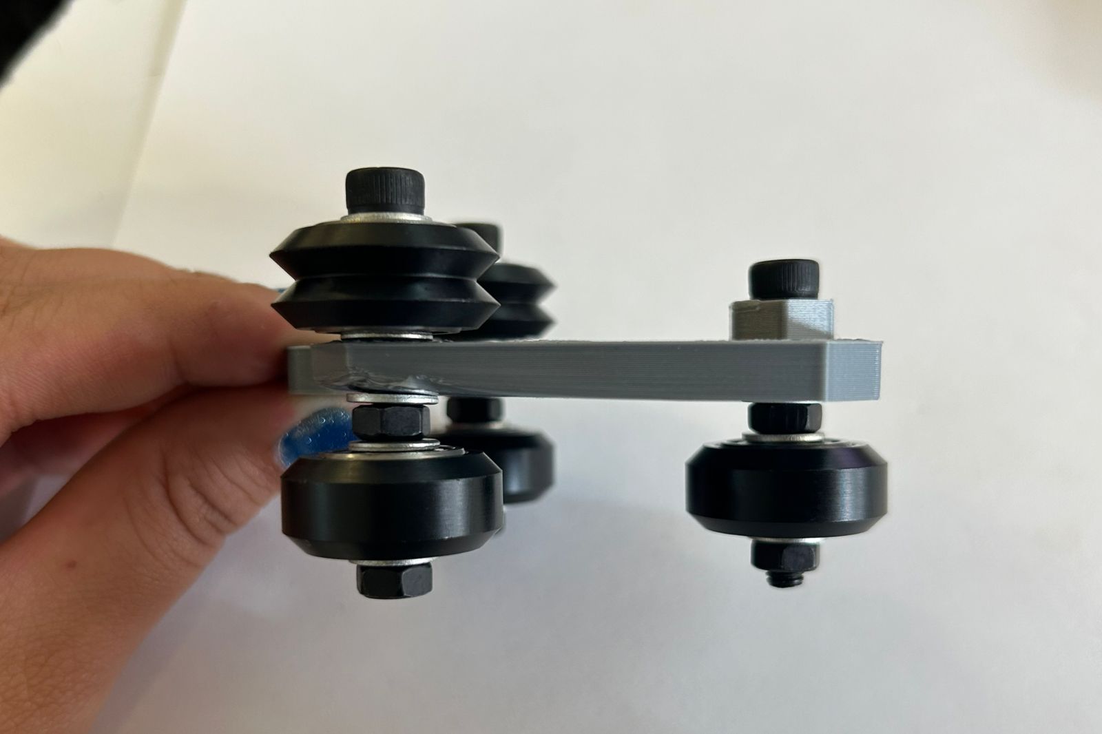
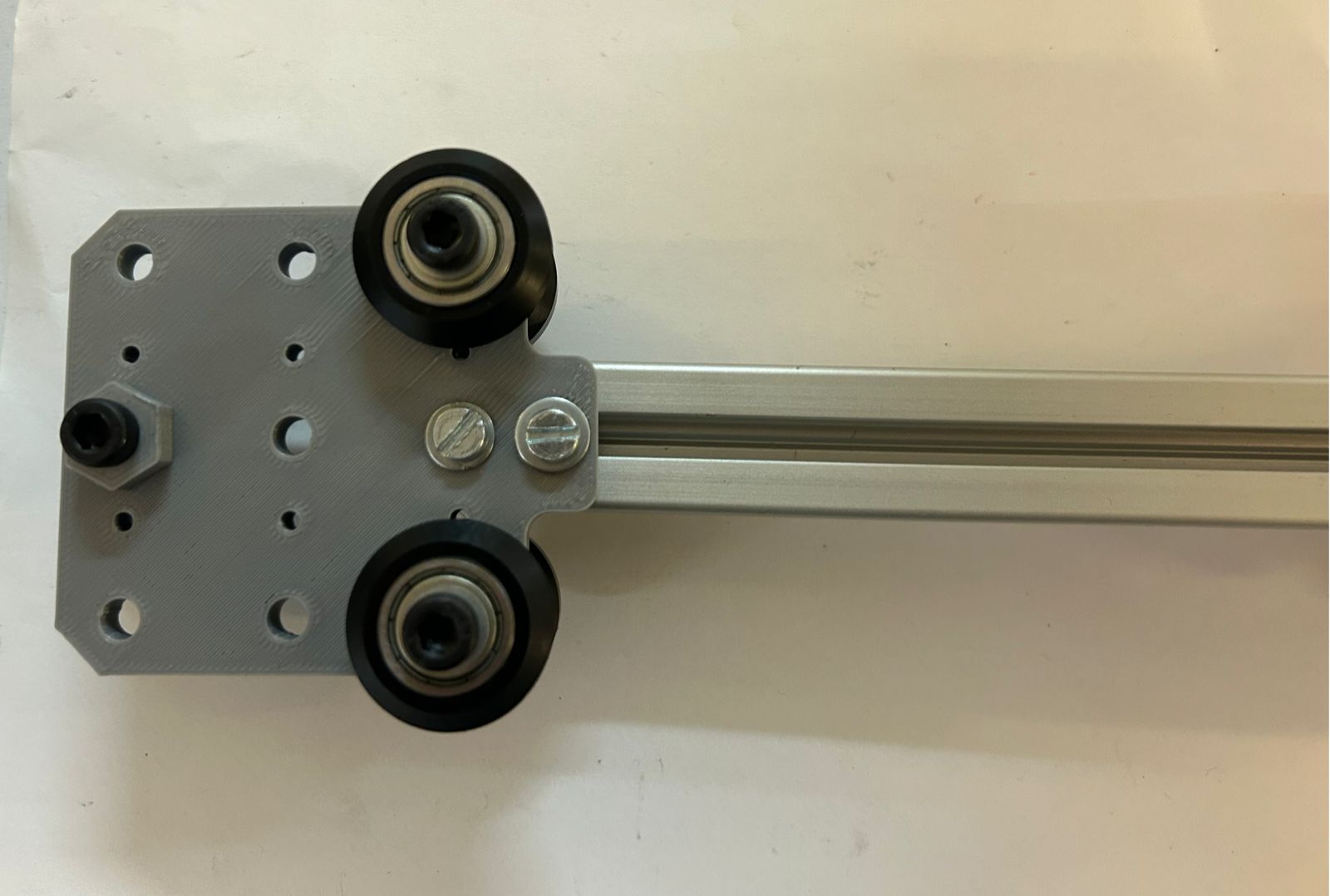
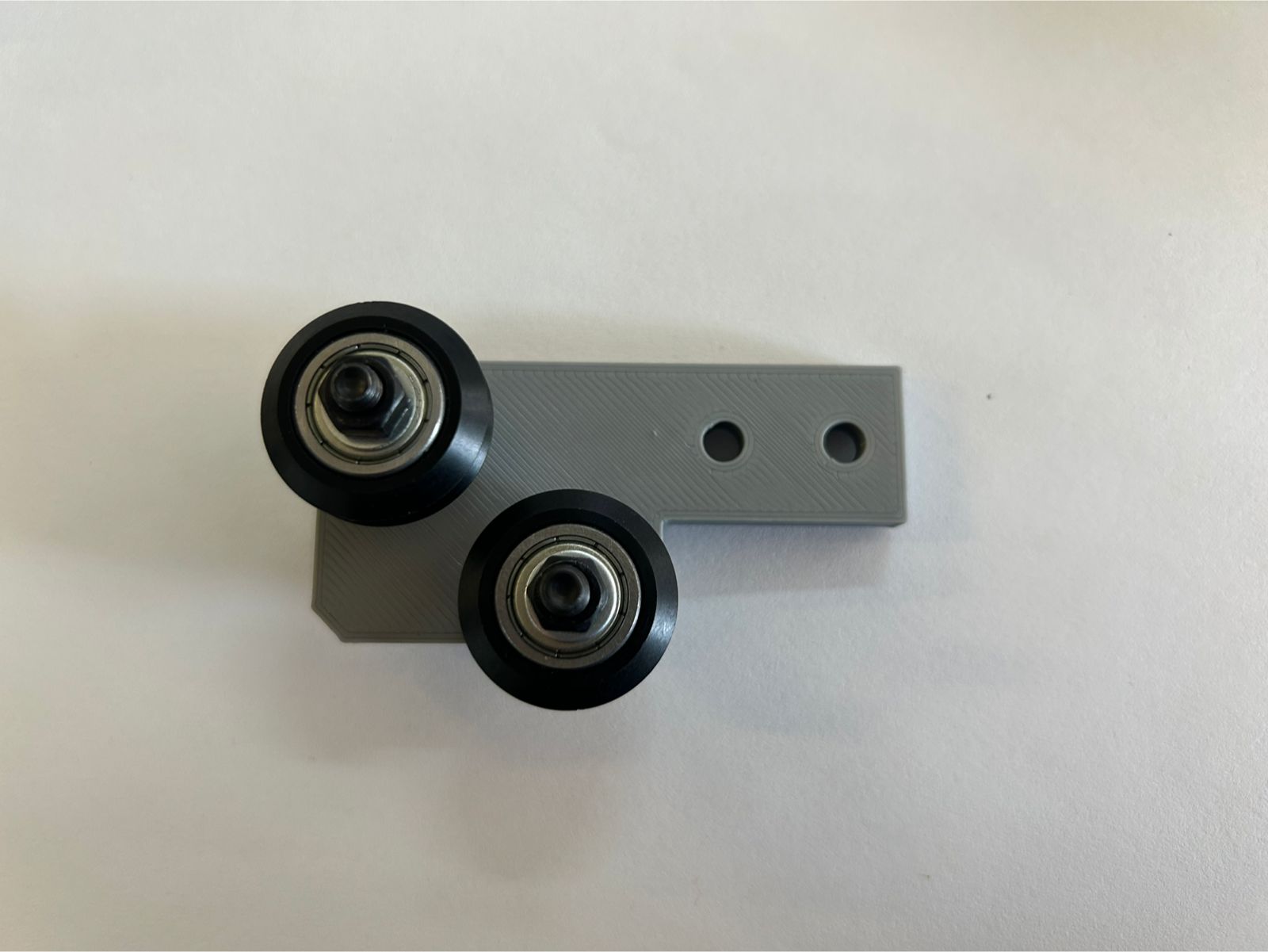
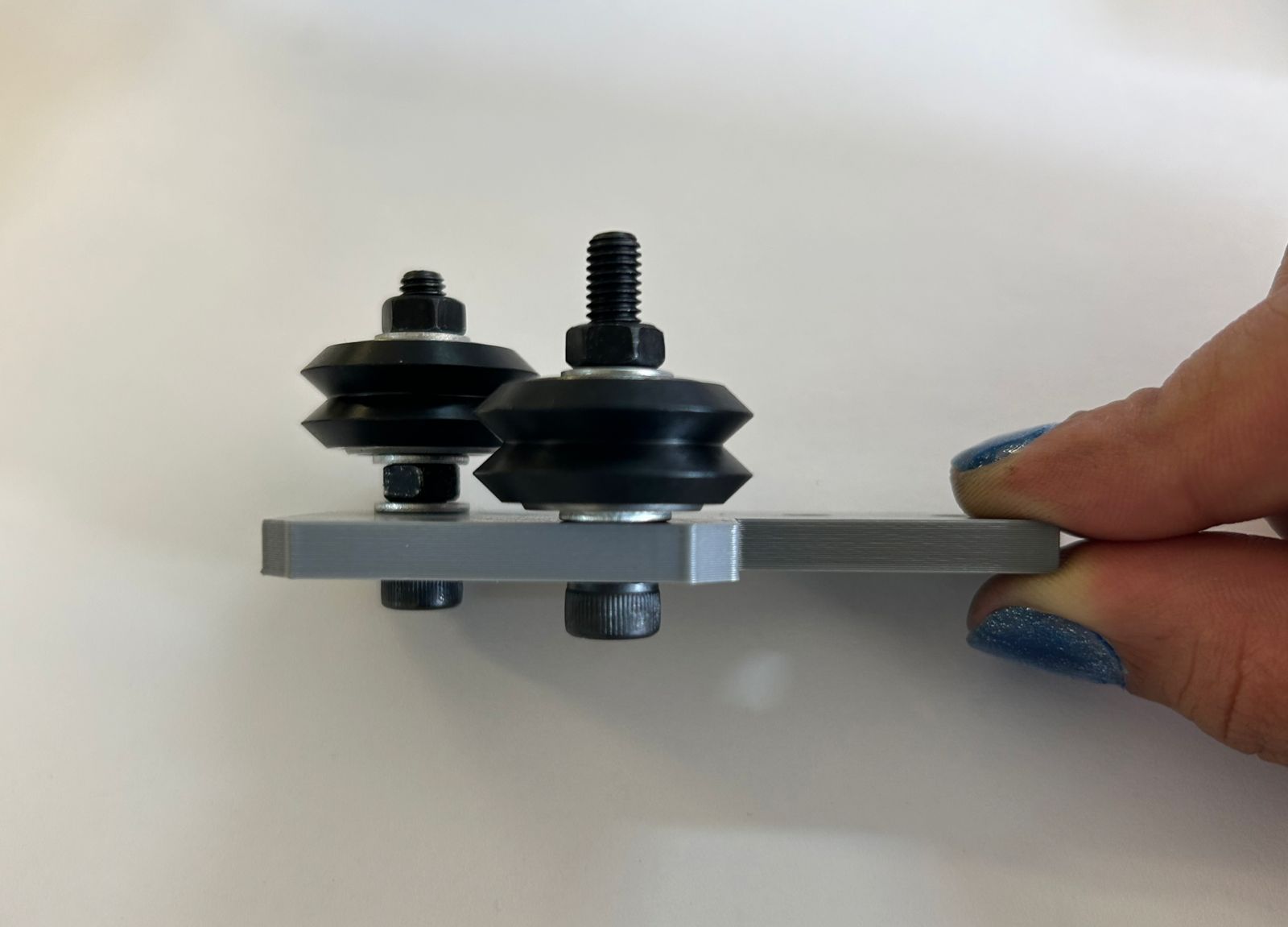
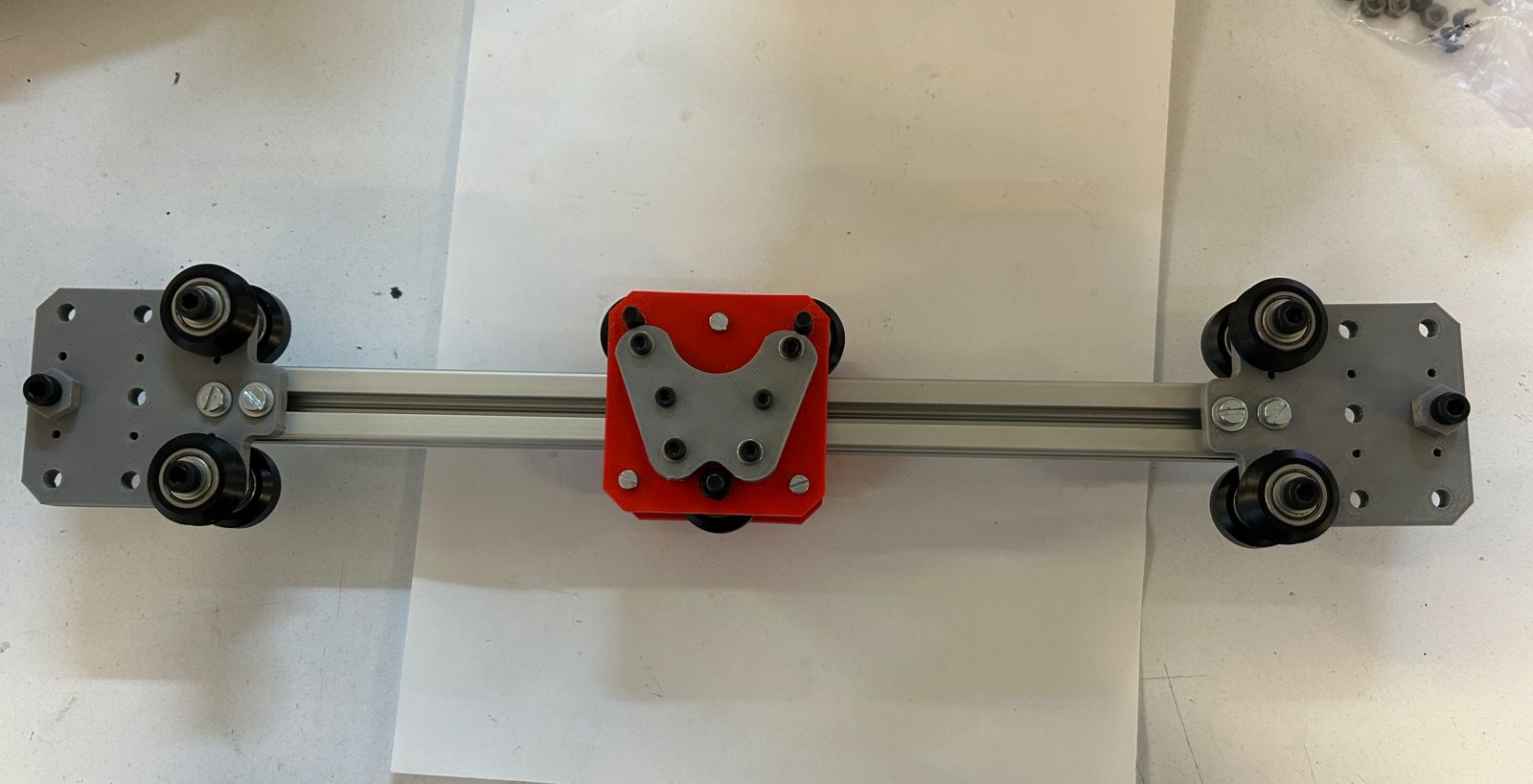
The Y-plates serve as the modules that attach to the central rail, allowing it to slide across the entire workspace to generate Y-axis movement. Each unit consists of three V-type Delrin wheels on the bottom, which glide along the tube to ensure structural stability. On the top, two dual V-wheels function as pulleys to drive the motion via the string system. This component is duplicated, as one is required for each side of the central rail.
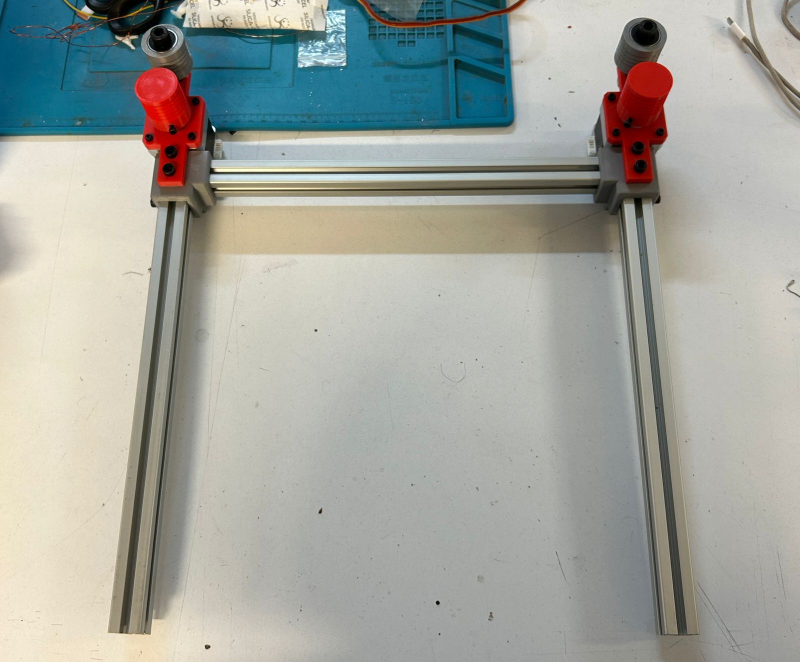
Motor and pulley
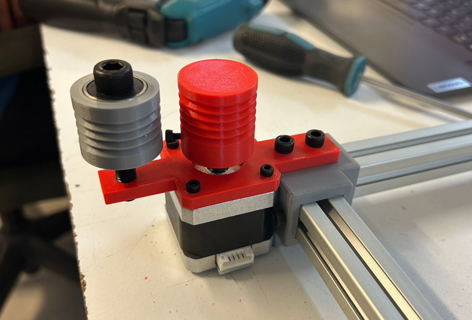
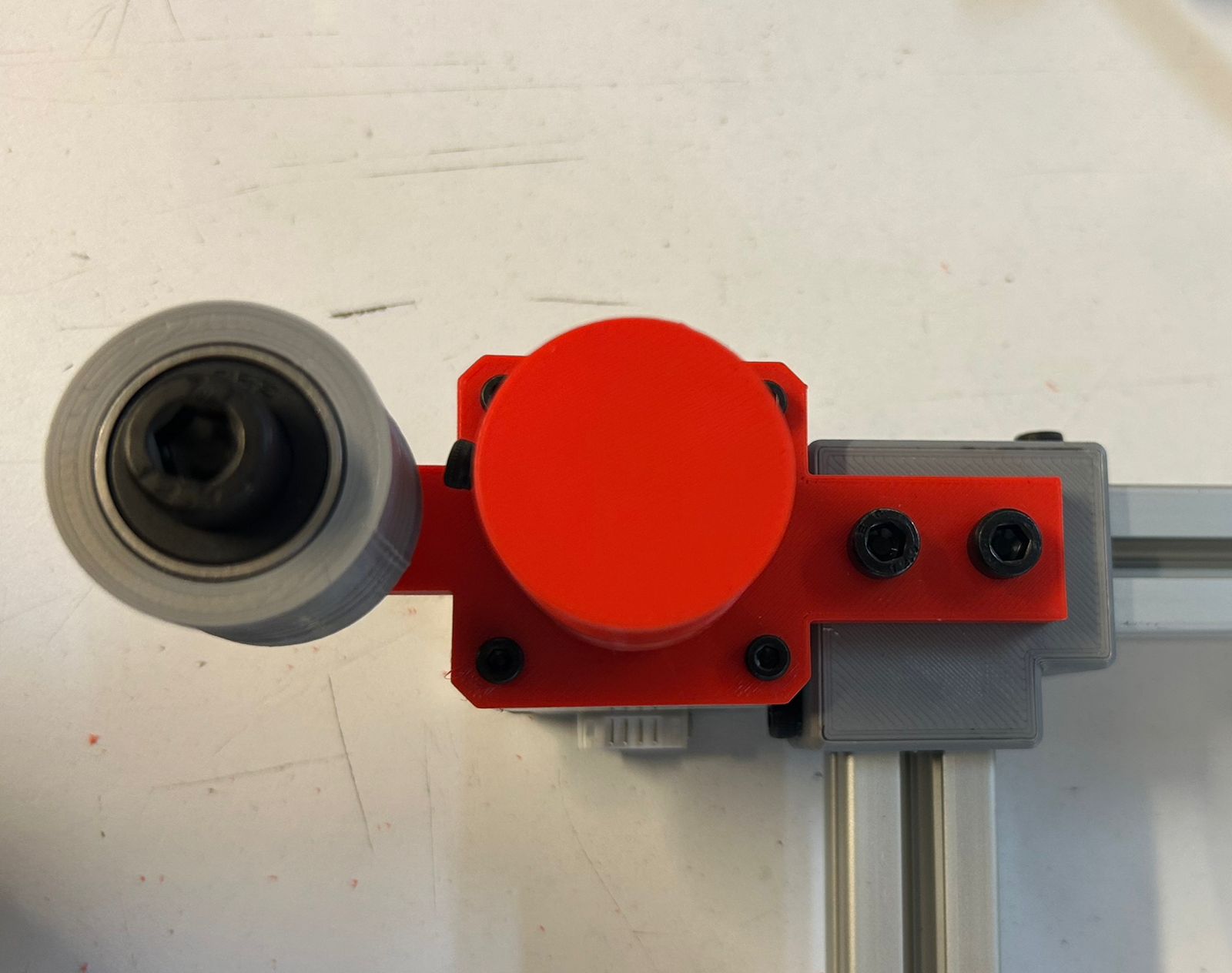
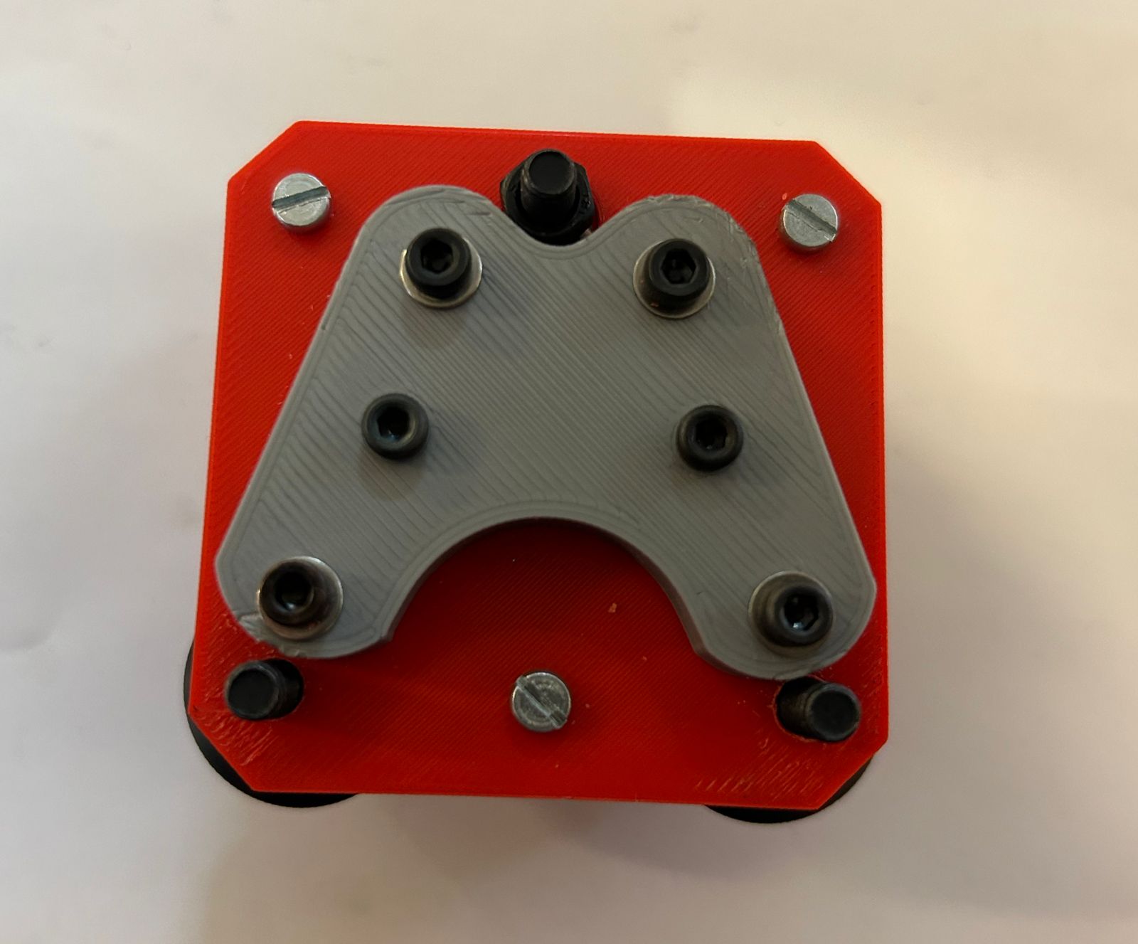
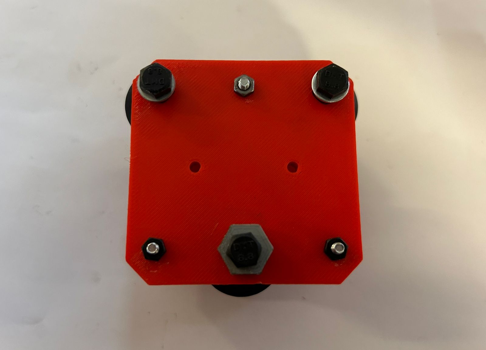
The motor module is secured to two corners of the structure. It features two pulleys, one mounted directly on the motor shaft and another aligned with it, which serve to wind and store the cable as it accumulates during operation.
Corners pulley
The pulley system modules are positioned at the corners opposite to the motors. Each module houses two dual V-wheels that act as pulleys to guide the string system. These pulleys are set at different heights to prevent the strings from overlapping. Two identical replicas of this module are required for the assembly.
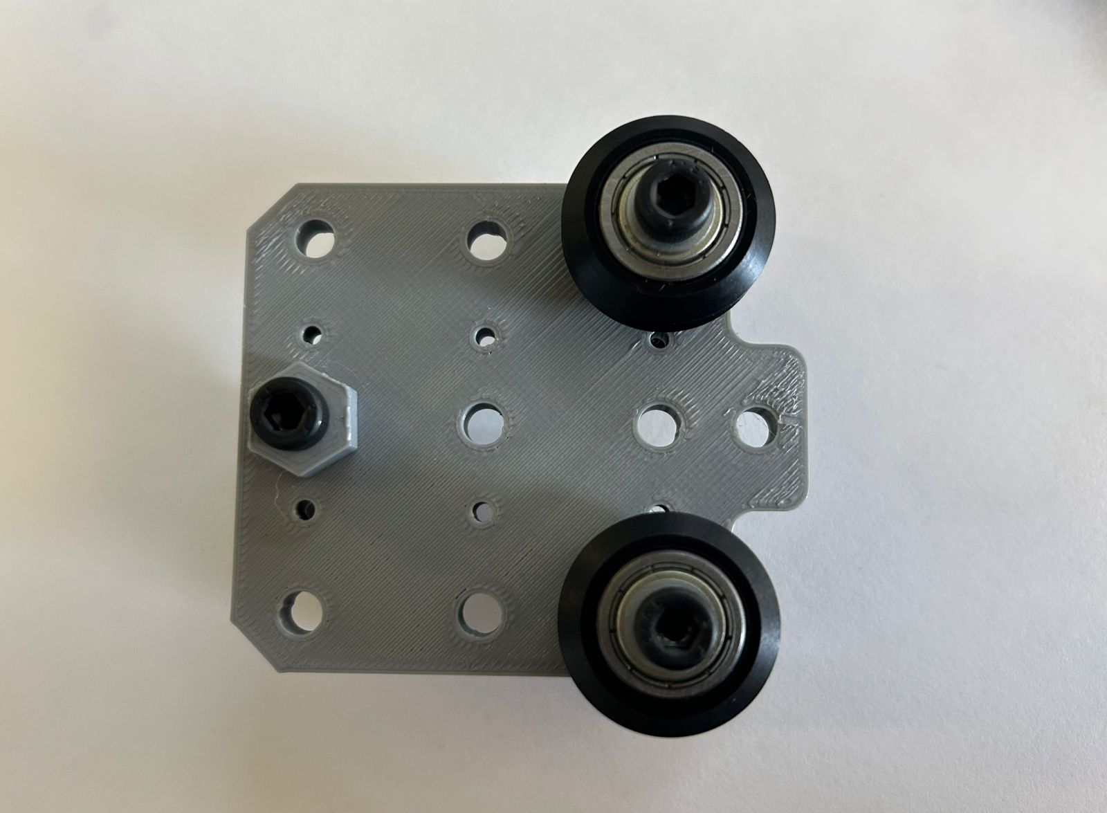
Carriage module
Finally, the toolhead carriage module is composed of three V-type wheels and a dual-plate assembly. The upper section features a dedicated component where the start and end points of the strings are secured and tied, completing the motion loop.
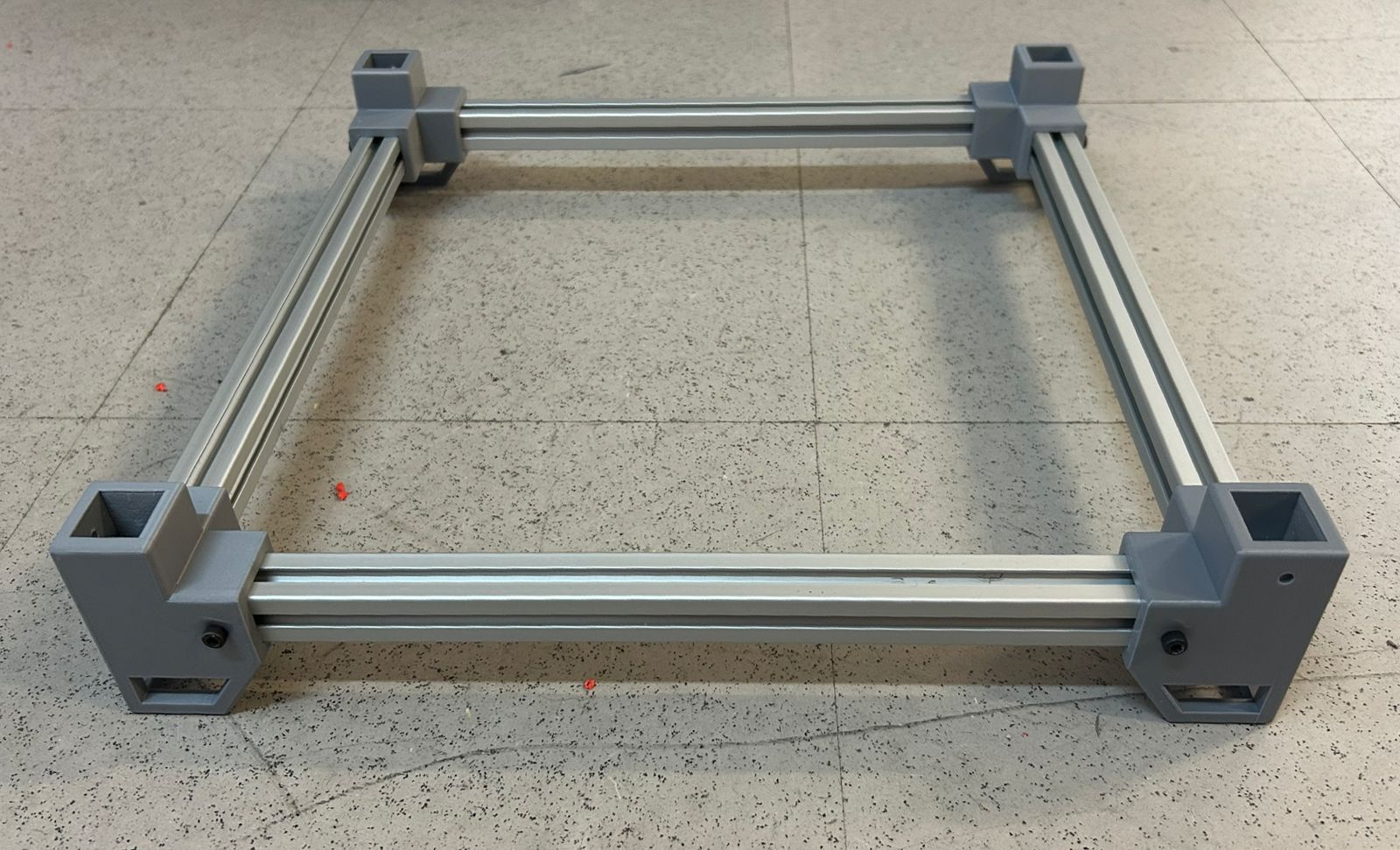
Assembly
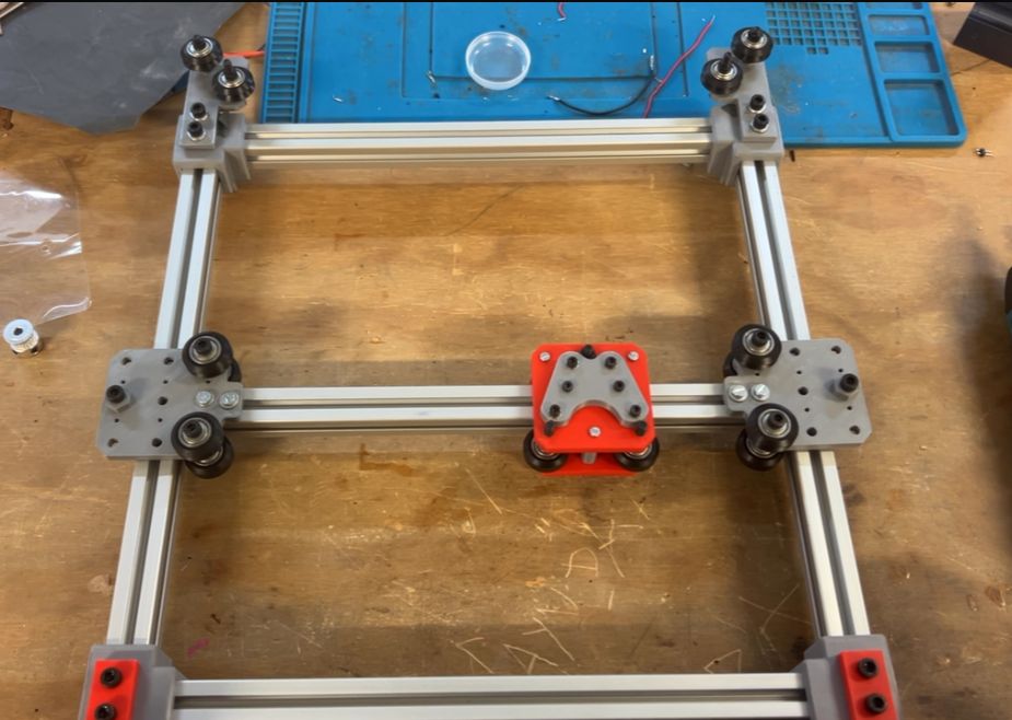
The assembly process began with the base frame, which consists of four profiles joined by four 3D-printed corner brackets.
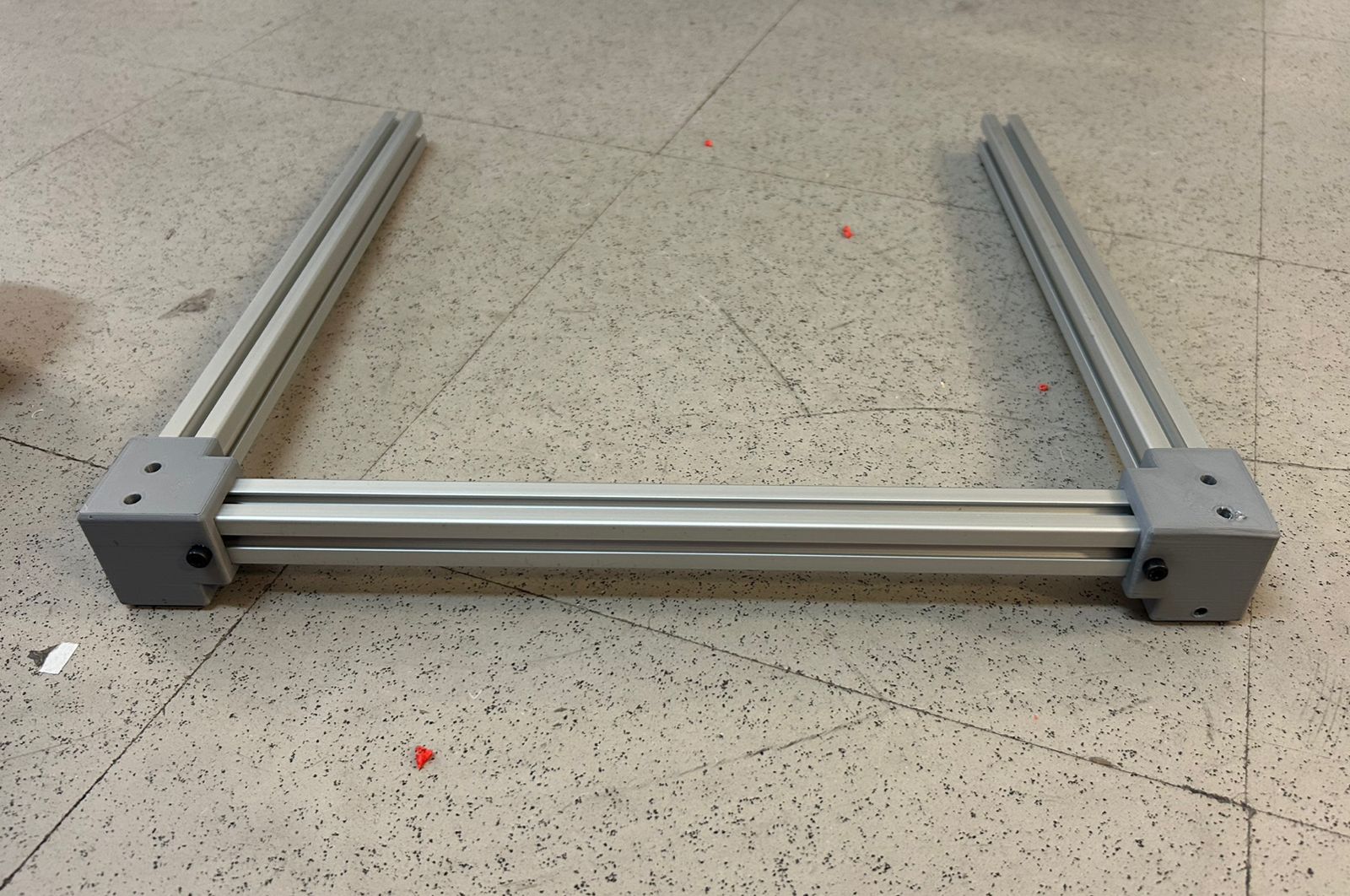
To assemble the top frame, only three sides are initially connected using the 3D-printed joints. This sequence is intentional, as it allows for an easier insertion of the central rail into the structure.
The motor modules are added and secured to the profile using screws. Ensure they are perfectly aligned with the rail to maintain proper motion geometry.
To assemble the central rail, the first Y-plate is mounted first, followed by the carriage plate, and finally, it is secured by attaching the second Y-plate.
Next, the central rail slides onto the two parallel rails, and the frame is closed by attaching the fourth profile. This step includes the pulley system modules, which must be inserted and linearly aligned with the profile.
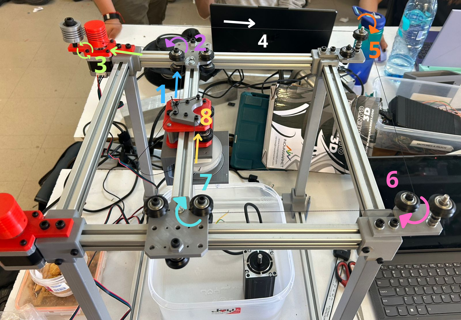
Estructure with threads
The string routing begins at one side of the carriage plate, leading into the Y-plate pulley. From there, it enters the motor module from the inside, starting from the bottom of the first spool and crossing in a figure-eight pattern between the two pulleys. It then exits from the outside toward the upper pulley on the opposite side, crosses over, and enters the lower corner pulley. Finally, it passes through a Y-plate pulley and terminates at the opposite corner of the carriage plate.
Testing
A dry run was performed without the strings to verify that the wheels rotated smoothly and to ensure there was minimal rolling friction.
Once the string was installed, the structure's mobility was tested again to verify smooth movement and proper tensioning across the entire system.
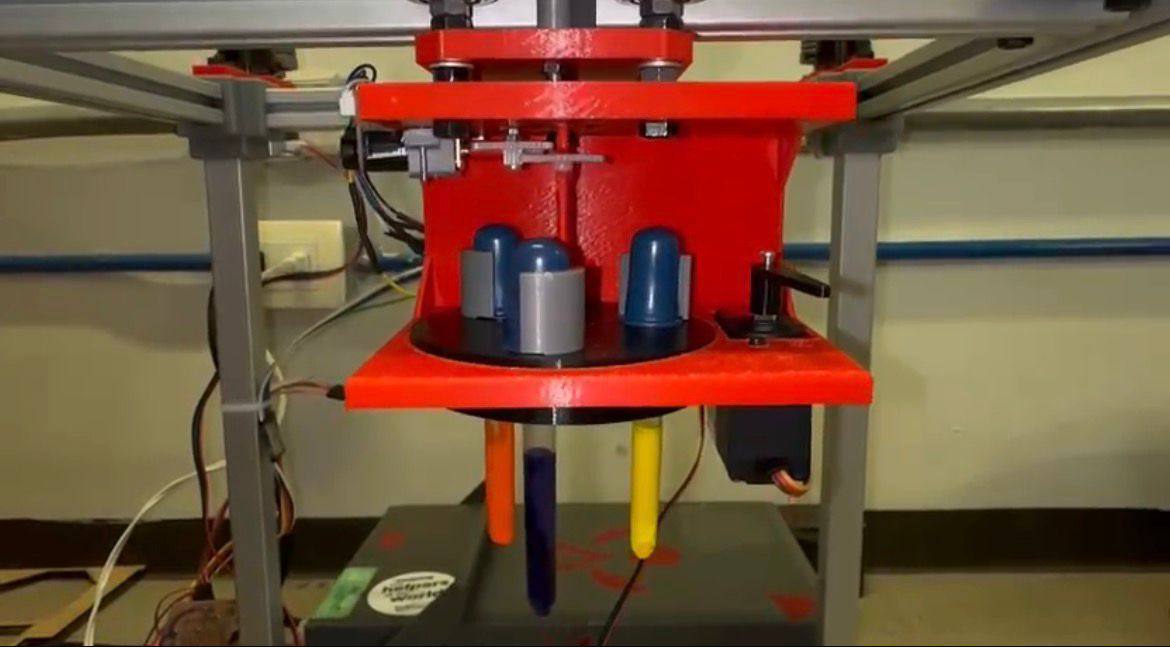
Ink rotary System
The machine's toolhead consists of a rotary system that houses three pipettes of different colors. It is powered by a DC motor that provides the rotational movement for color selection, and a servomotor that acts as the plunger, pressing the pipette to release the ink drop
BOARDS
CNC-SHIELD
SCHEMATIC DESIGN
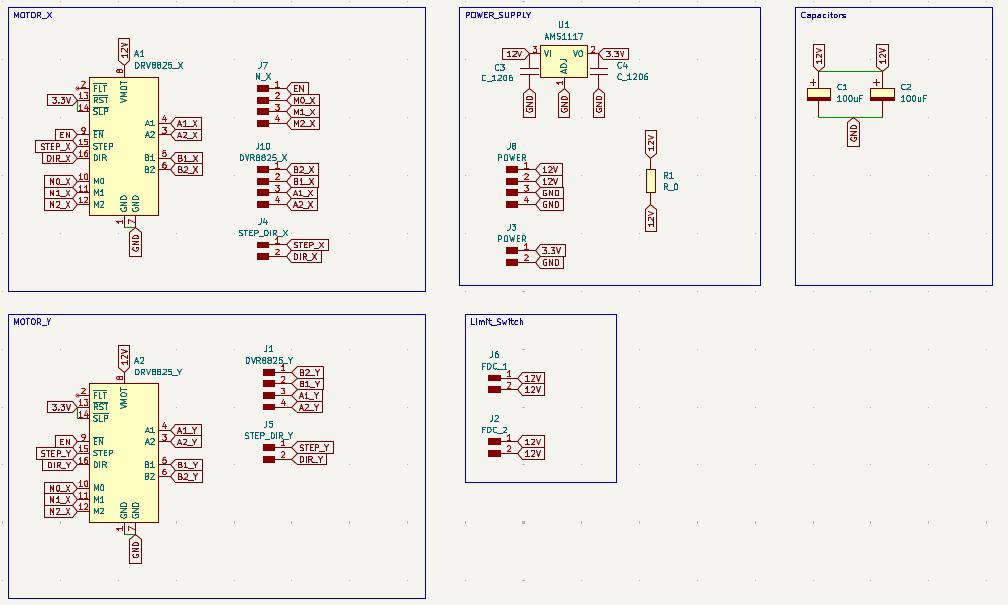
Motor X
To control the X-axis, a NEMA 17 motor and the DVR8825 controller were used. In the schematic, the DVR8825 pins are connected to external pins via global labels, in accordance with the DVR8825 pinout.
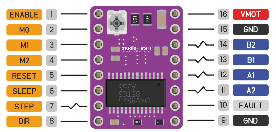
It is also important to note that the X and Y motors share four pins: ENABLE, M0, M1, and M2, since they are intended to have the same step size and the same enable signal.
Motor Y
To control the Y-axis, a NEMA 17 motor and the DVR8825 controller were used. In the schematic, the DVR8825 pins are connected to external pins via global labels, in accordance with the DVR8825 pinout. Here it was only used the specific pins for this second driver.
Power Supply
To regulate and reduce the initial voltage it was used the AMS1117. It requires two capacitors for device stability, one in the input (12V) and one in output (3.3v). Both of 10µF. Then more pins were added, two for 12V and two for GND. It also was added two more pins for 3.3V and GND also were added to the output of the regulator.
Limit Switch
Two pairs of pins were added to connect two limit switches, designed to stop the CNCs movement if it exceeds the mechanical limit. When the limit switch is triggered, it interrupts the power supply.
Capacitors
The capacitors are 100 μF and are connected in parallel. They are configured as decoupling capacitors to filter out voltage spikes and protect the drivers.
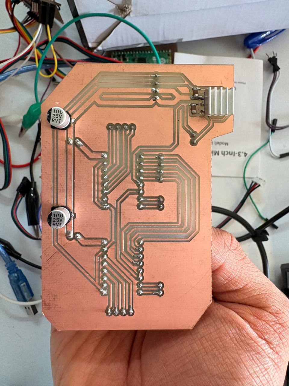
PCB DESIGN
After using KiCads calculation tool, two trace widths were selected: 2 mm and 0.8 mm. The 2 mm width was used for the 12 V power supply to ensure the traces were robust. The 0.8 mm width was used for all other traces.
- The outline width is 2 mm and its layer is Edge.Cuts.
- The track's width is 0.8 mm - 2 mm and its layer is F.Cu.
- The Holes layer is User.1.
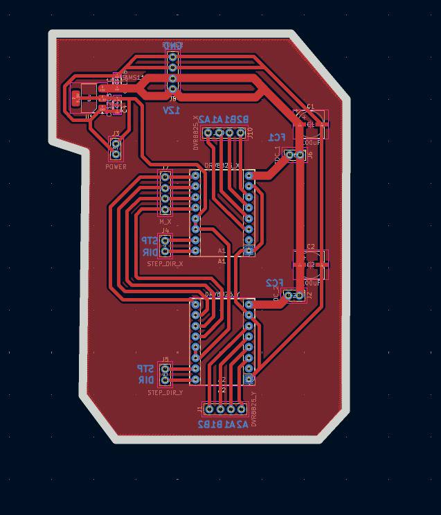
Then using the change side tool, the board was flipped. That action was important because the drivers will be on the underside of the plate.
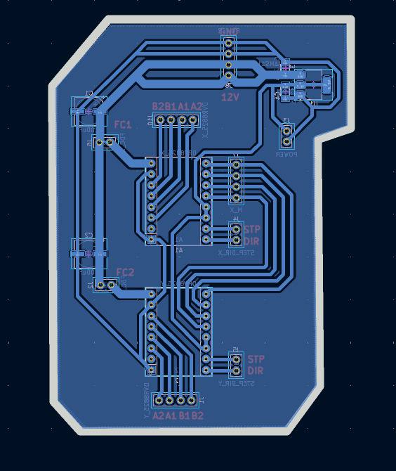
RESULT
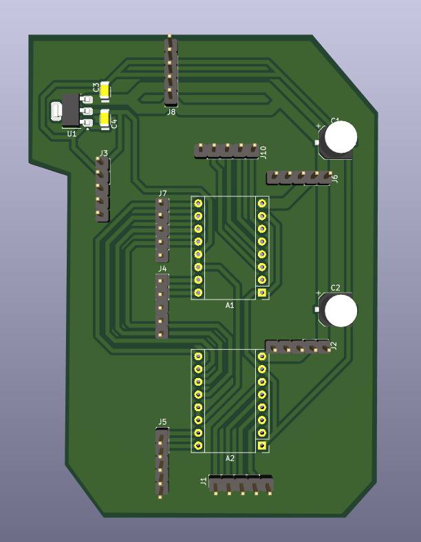
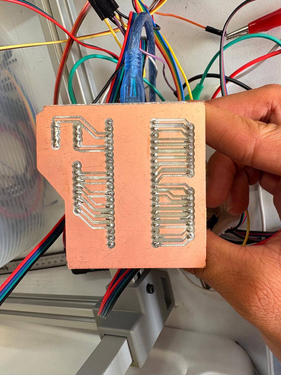
PI PICO 2
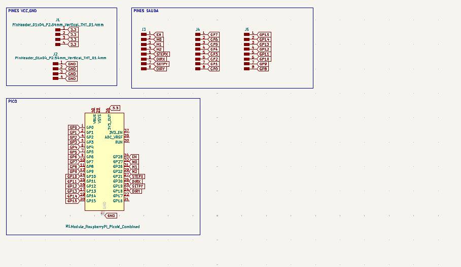
For the Pi Pico 2, only this component was used, along with external pins connected to the boards pins via global labels. Since all ground pins are connected internally, ground pins were omitted from the board layout, and four separate ground pins were added instead. Four separate 3.3V pins were also added.
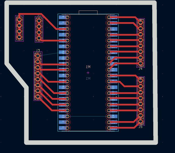
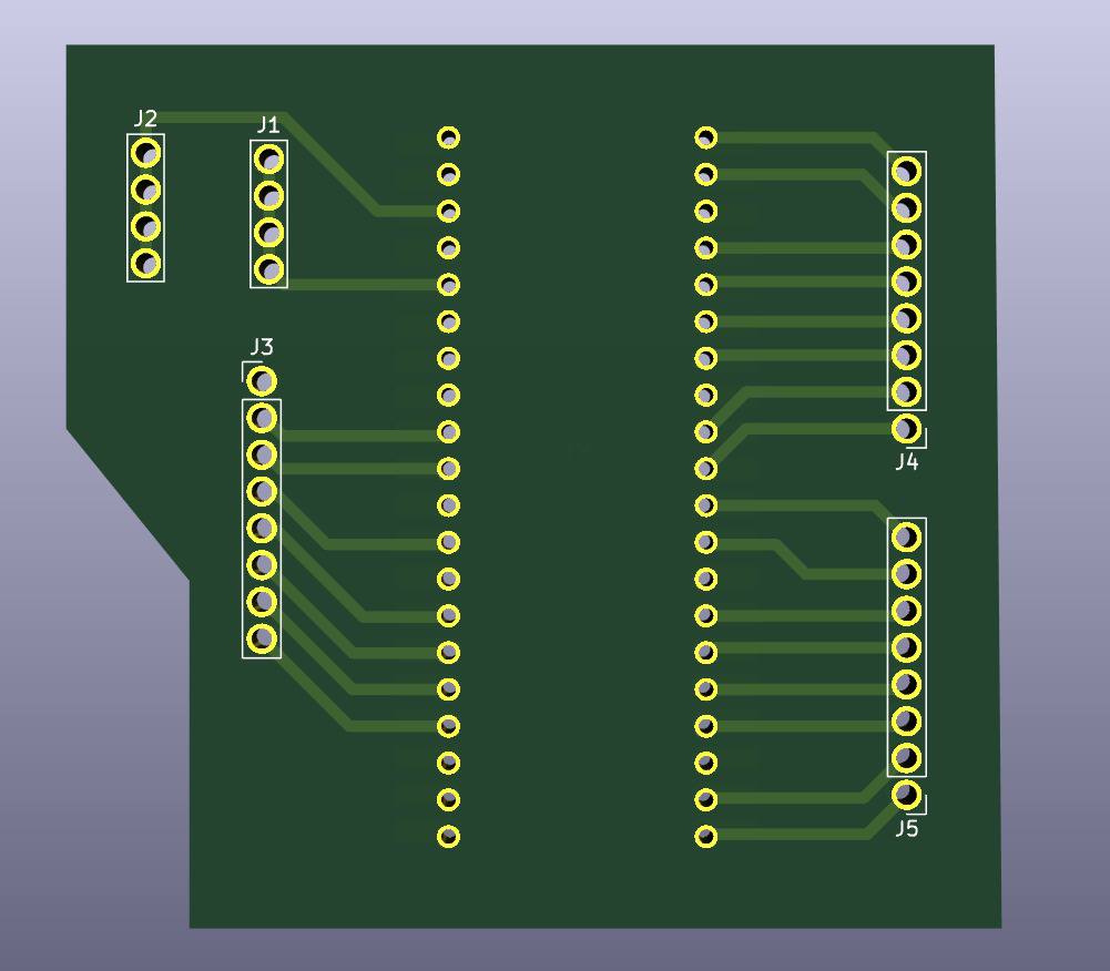
PCB
After using KiCads calculation tool only one width was selected: 0.8 mm. That width was used for all the traces. Using the change side tool the Raspberry Pi Pico 2 was flipped to put it on the underside of the plate.
- The outline width is 2 mm and its layer is Edge.Cuts.
- The track's width is 0.8 mm - 2 mm and its layer is F.Cu.
- The Holes layer is User.1.
RESULT
EXTRA PINS
SCHEMATIC DESIGN
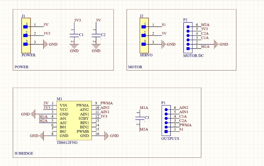
Power
Pins were placed for the power supply, and two decoupling capacitors were installed to prevent voltage spikes.
Motor
To control the N20 motor and the servo motor, global labels were assigned to their pins to connect them to external pins and the H-bridge.
H-BRIDGE
The H-bridge was installed to enable programmable control of the N-20 motor. Subsequently, pins were added to connect the motor, along with a capacitor to prevent voltage spikes from reaching the N-20 motor.
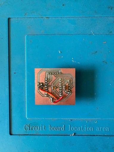
PCB DESIGN
After using ALTIUM calculation tool a 0.8 mm width was selected. Two layers were used. The red tracks are for the PCB, and the blue ones are for two cables we used connect in order to not use 0 resistors.
- The outline width is 2 mm, and its layer is Mechanical Layer.
- The red tracks width is 0.8 mm, and its layer is Top Layer.
- The blue tracks width is 0.8 mm, and its layer is Bottom Layer.
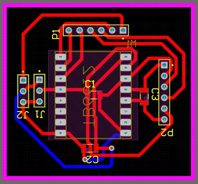
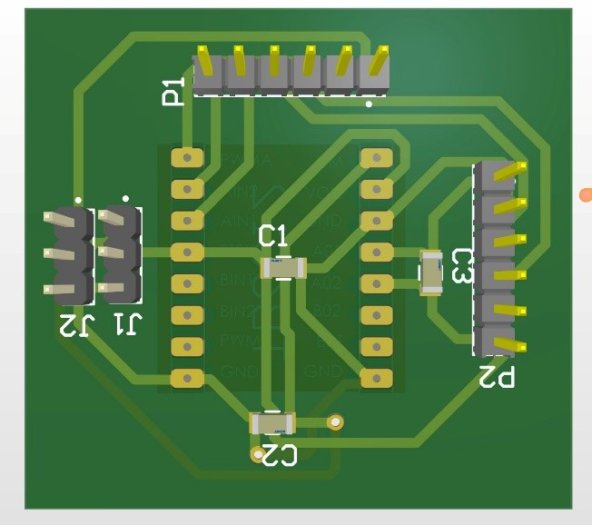
RESULT
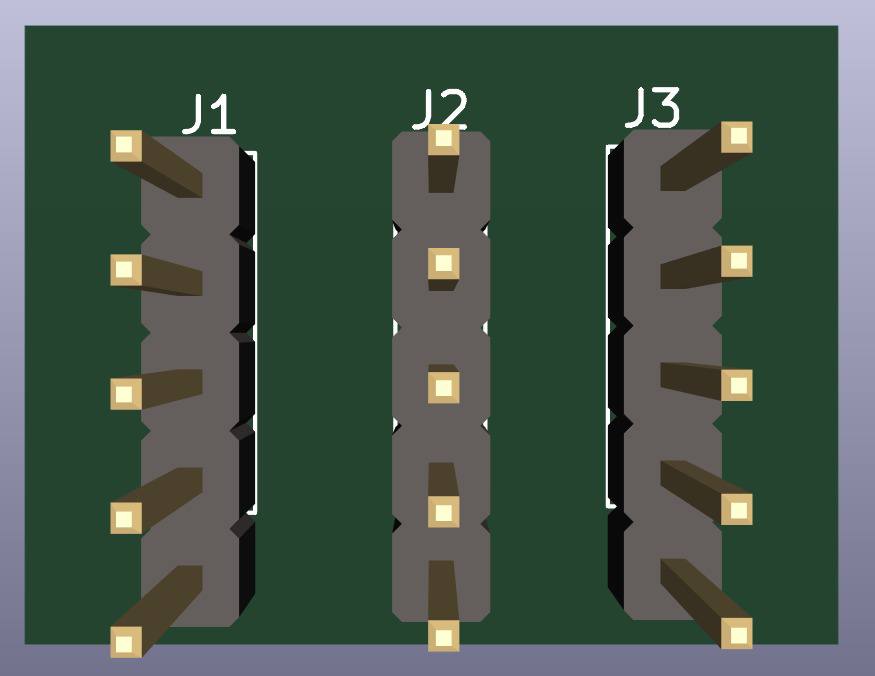
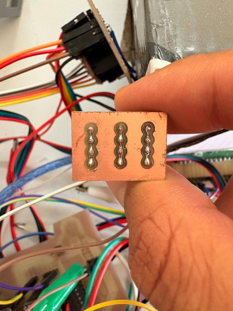
EXTRA PINS
SCHEMATIC DESIGN
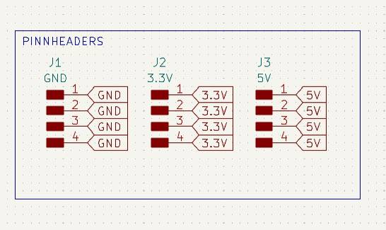
The extra pins board was created because more GND pins were needed during the process of connecting the modules. The schematic consists of just three columns of four pins connected to each other.
PCB DESIGN
After using KiCads calculation tool only one width was selected: 0.8 mm. That width was used for all the traces.
- The outline width is 2 mm and its layer is Edge.Cuts.
- The track's width is 0.8 mm - 2 mm and its layer is F.Cu.
- The Holes layer is User.1.
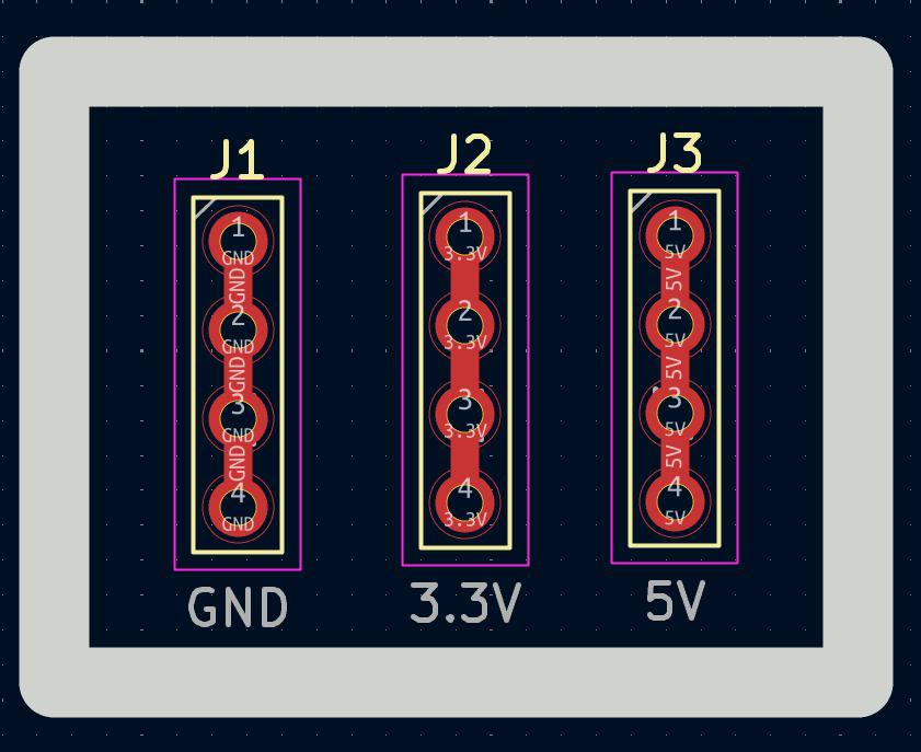
RESULT
EXPORTING AS SVG
To export SVG first we must go to the top left corner and press file, after that select Fabrication Outputs. Then choose Gerbers and change the plot format to SVG. After that select the layers used and select the folder where the files are going to be saved. Finally click on plot.
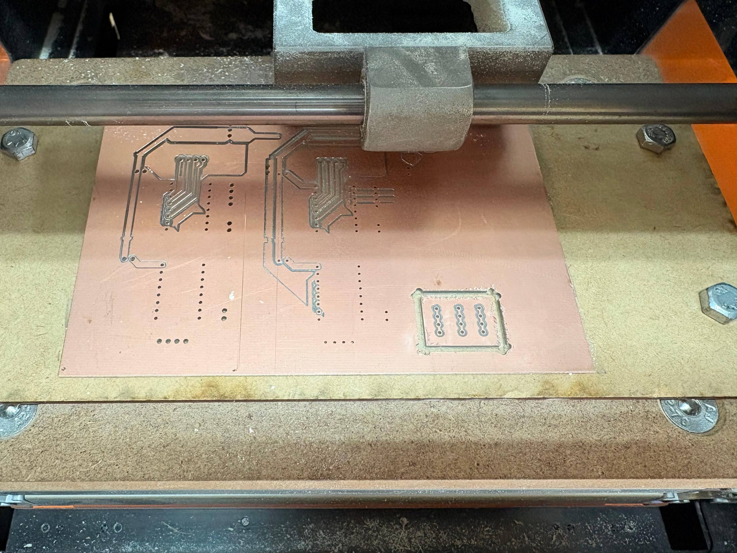
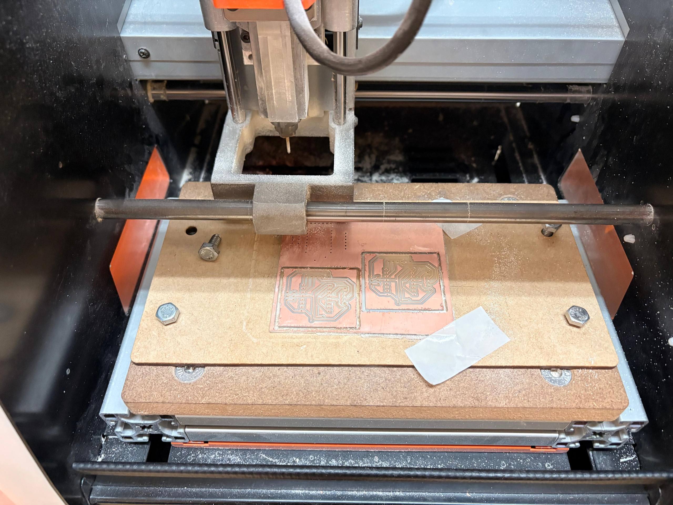
CUTTING
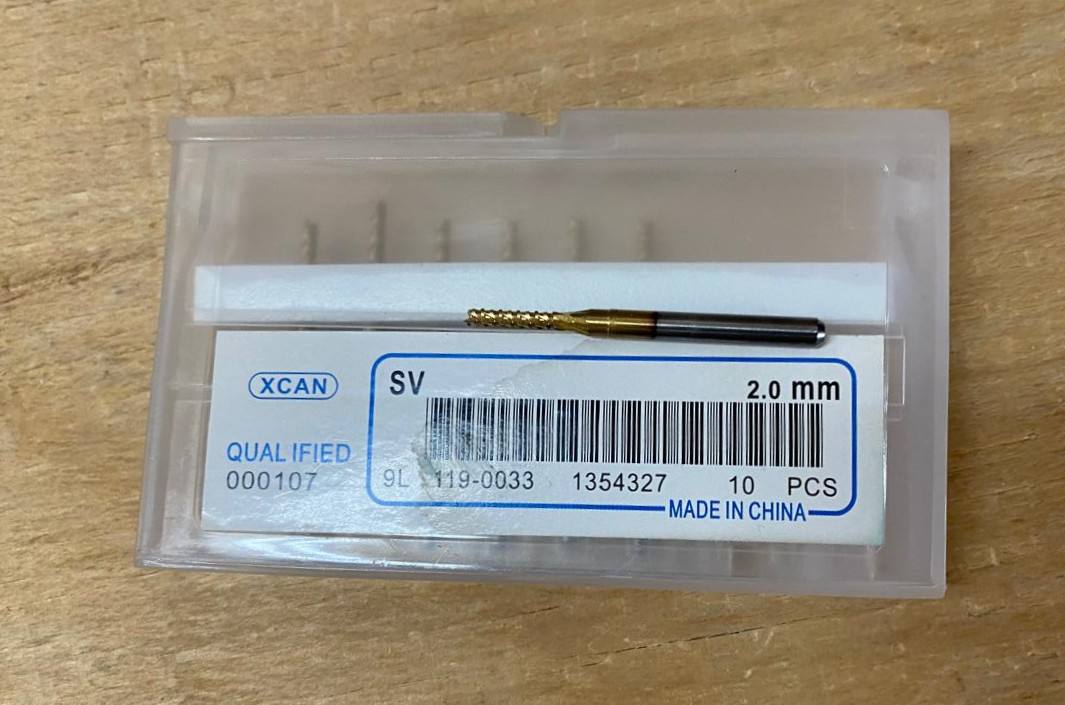
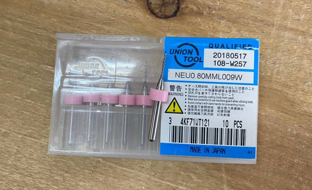
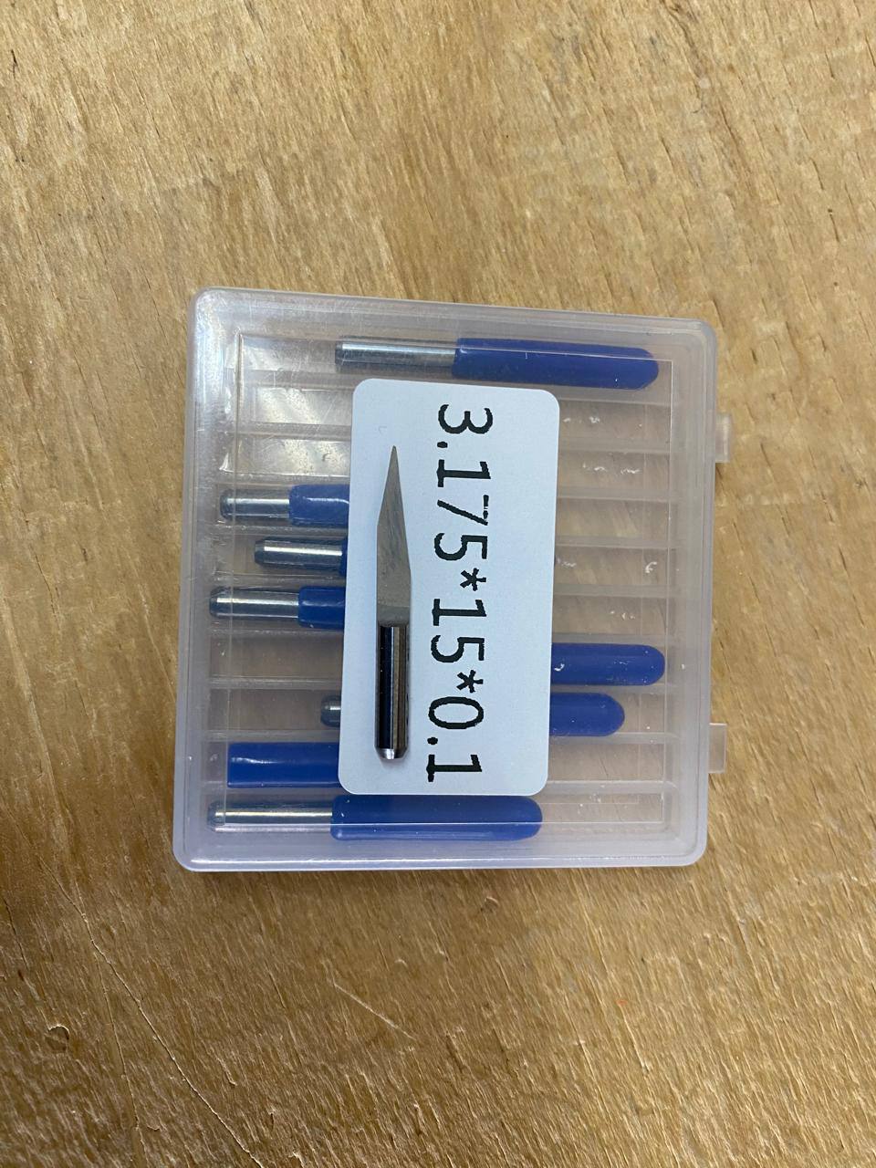
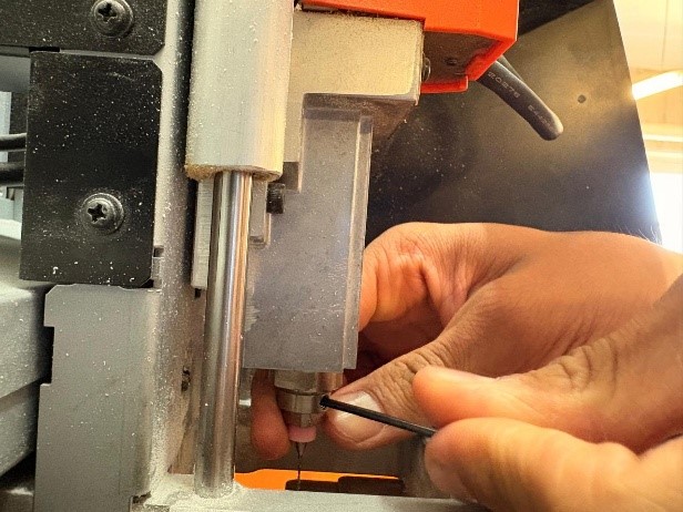
The tools for cutting are these ones: The first one is for drilling and making the outline. The second one is for drilling the holes and the third one is for the tracks.
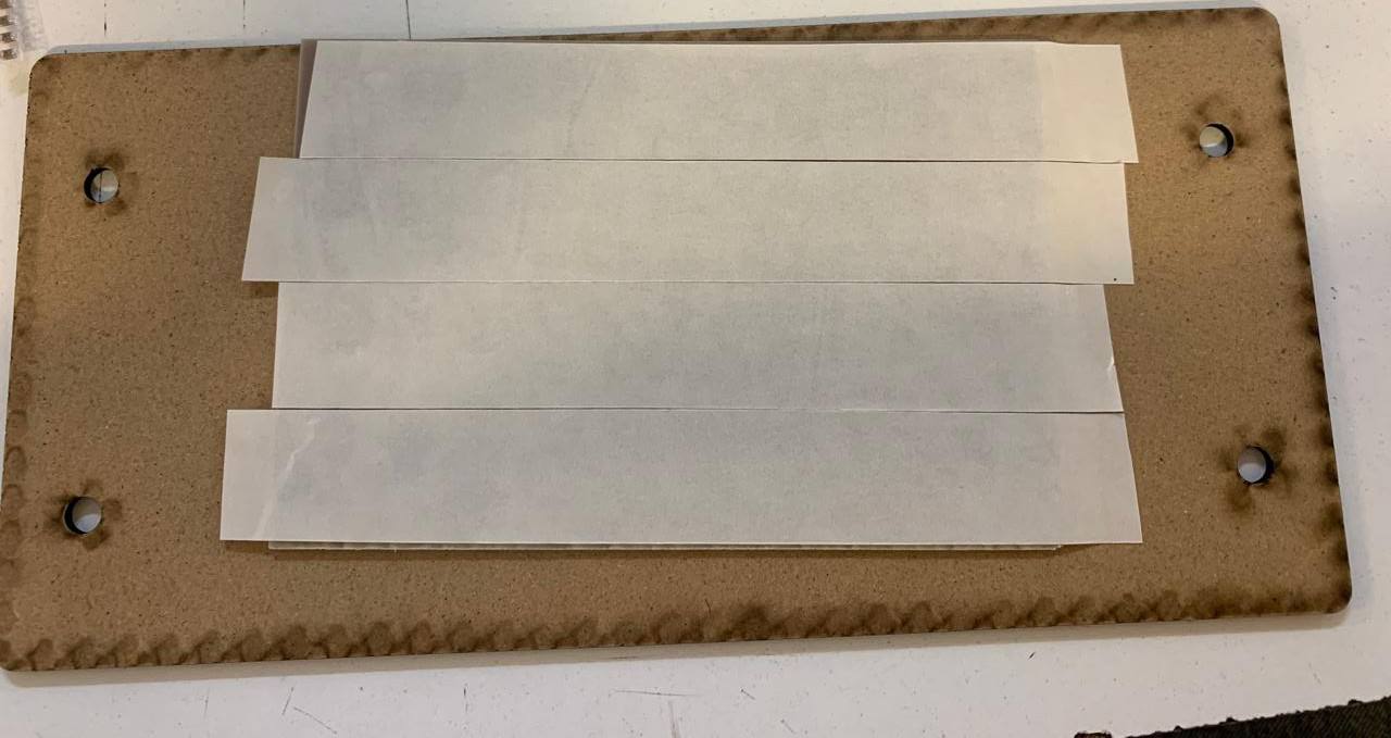
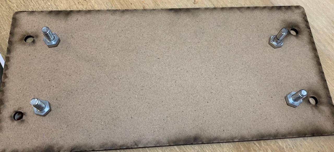
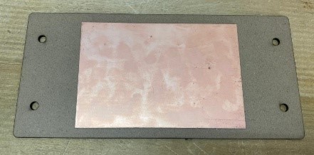
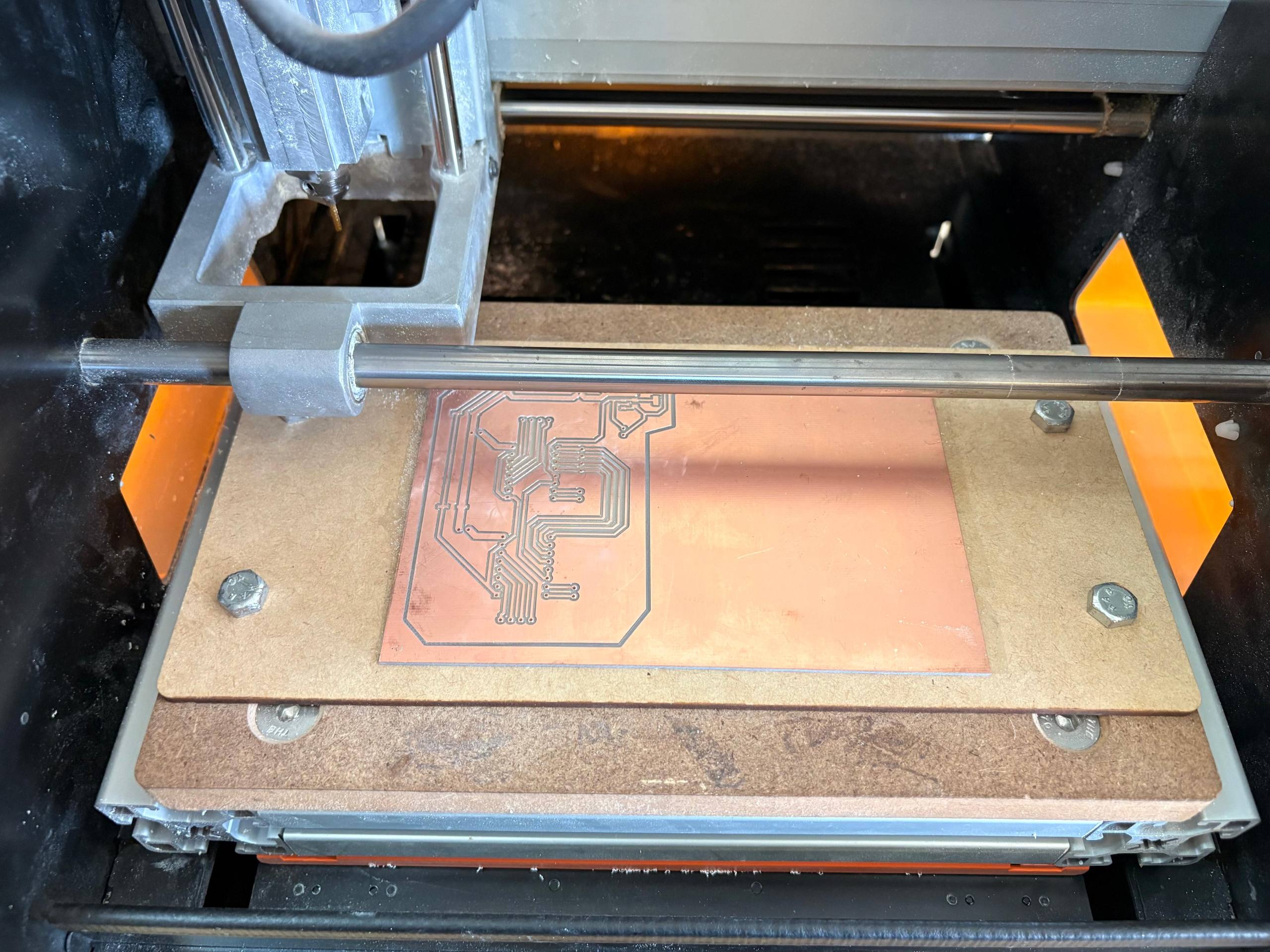
To place the copper plate first we have to use double-sided tape in the back of the plate, then place it over the sacrifice bed and finally putting them inside the SRM-20 monofab.
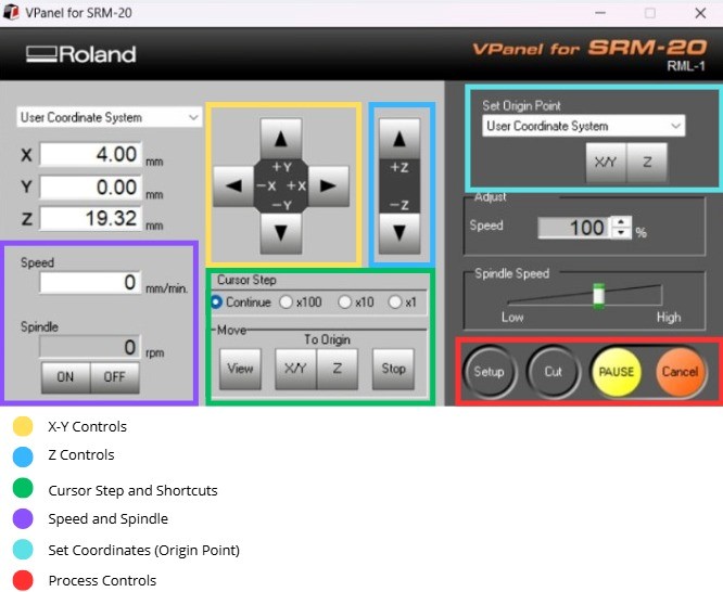
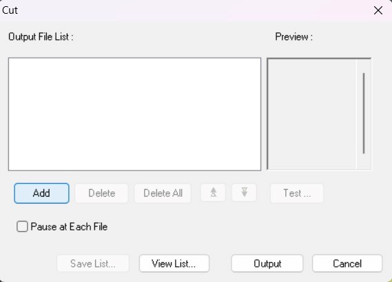
Then we must set the origin in VPANEL. Change the tool and add our files
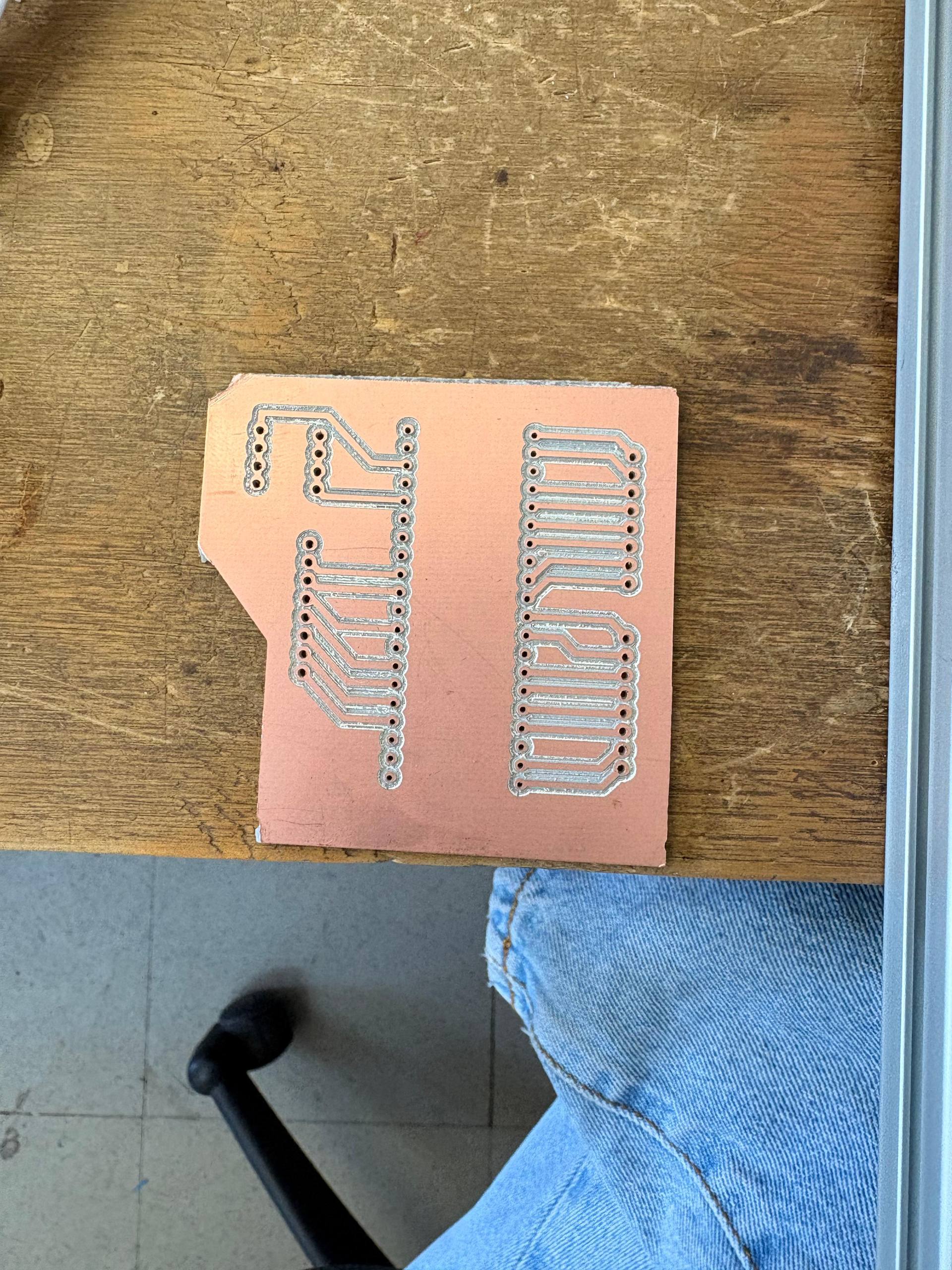
RESULTS
SOLDERING RESULTS
PROGRAMMING
CODE
#include <AccelStepper.h>
#include <Servo.h>

// -------- PINS (PICO 2) --------
#define enableSteppers 0
#define stepA 3
#define dirA  7
#define stepB 1
#define dirB  2

const int PWMA = 8;
const int AIN1 = 11;
const int AIN2 = 12;
const int pinServo = 15;

// -------- OBJECTS --------
AccelStepper motorA(1, stepA, dirA);
AccelStepper motorB(1, stepB, dirB);
Servo myservo;

// -------- CONFIG --------
const float velocidadNema = 200.0;
const float aceleracionNema = 400.0;

// N20
const float MS_POR_VUELTA = 30000.0;
const float MS_POR_GOTERO = MS_POR_VUELTA / 3.0;

// SERVO
const int SERVO_REPOSO = 180;
const int SERVO_GOTA   = 60;

// GLOBAL POSITION
long posX = 0;
long posY = 0;

void setup() {
  Serial.begin(115200);

  pinMode(enableSteppers, OUTPUT);
  digitalWrite(enableSteppers, LOW);

  motorA.setMaxSpeed(velocidadNema);
  motorA.setAcceleration(aceleracionNema);

  motorB.setMaxSpeed(velocidadNema);
  motorB.setAcceleration(aceleracionNema);

  pinMode(PWMA, OUTPUT);
  pinMode(AIN1, OUTPUT);
  pinMode(AIN2, OUTPUT);

  pararN20();

  myservo.attach(pinServo, 500, 2400);
  myservo.write(SERVO_REPOSO);

  Serial.println("CNC AUTO READY");
}

void loop() {
  if (Serial.available()) {
    String comando = Serial.readStringUntil('\n');
    comando.trim();

    // -------- JOG --------
    if (comando.startsWith("JOG")) {
      int c1 = comando.indexOf(',');
      int c2 = comando.indexOf(',', c1 + 1);

      int dx = comando.substring(c1 + 1, c2).toInt();
      int dy = comando.substring(c2 + 1).toInt();

      posX += dx;
      posY += dy;

      moverCoreXY(dx, dy);

      Serial.println("JOG OK");
    }

    // -------- GOTO --------
    else if (comando.startsWith("GOTO")) {
      int c1 = comando.indexOf(',');
      int c2 = comando.indexOf(',', c1 + 1);

      long targetX = comando.substring(c1 + 1, c2).toInt();
      long targetY = comando.substring(c2 + 1).toInt();

      long dx = targetX - posX;
      long dy = targetY - posY;

      posX = targetX;
      posY = targetY;

      moverCoreXY(dx, dy);

      Serial.println("GOTO OK");
    }

    // -------- DROP --------
    else if (comando == "DROP") {
      myservo.write(SERVO_GOTA);
      delay(400);

      digitalWrite(AIN1, HIGH);
      digitalWrite(AIN2, LOW);
      analogWrite(PWMA, 160);

      delay(2000);

      pararN20();
      delay(100);
      myservo.write(SERVO_REPOSO);

      Serial.println("DROP OK");
    }

    // -------- COLOR --------
    else if (comando == "COLOR") {
      digitalWrite(AIN1, HIGH);
      digitalWrite(AIN2, LOW);
      analogWrite(PWMA, 180);

      delay((int)MS_POR_GOTERO);

      pararN20();
      Serial.println("COLOR OK");
    }

    // -------- SET ZERO --------
    else if (comando == "SET_ZERO") {
      posX = 0;
      posY = 0;

      motorA.setCurrentPosition(0);
      motorB.setCurrentPosition(0);

      Serial.println("ZERO OK");
    }

    // -------- HOME --------
    else if (comando == "HOME") {
      motorA.moveTo(0);
      motorB.moveTo(0);

      posX = 0;
      posY = 0;

      Serial.println("HOME OK");
    }
  }

  motorA.run();
  motorB.run();
}

// -------- COREXY --------
void moverCoreXY(long dx, long dy) {
  long moveA = dx + dy;
  long moveB = dx - dy;

  motorA.move(moveA);
  motorB.move(moveB);
}

// -------- STOP N20 --------
void pararN20() {
  digitalWrite(PWMA, LOW);
  digitalWrite(AIN1, LOW);
  digitalWrite(AIN2, LOW);
}
CODE EXPLANATION
This code functions as the control for a CNC machine that uses a CoreXY system for positioning and a circular carousel for dispensing. In this setup, the stepper motors move the main assembly, a DC motor (N20) rotates the carousel base to select different droppers, and a servo motor acts as a mechanical press to squeeze those droppers against a stationary wall.
Pin Definitions and Hardware Mapping
The code starts by assigning the Raspberry Pi Pico 2's physical pins to the machine's components. The stepper motors, which handle the X and Y movement of the assembly, are assigned to pins 1, 2, 3, and 7, while pin 0 is used as a unique enable pin to power the drivers. The N20 motor (the carousel base) is connected to an H-bridge via pins PWMA, AIN1, and AIN2, allowing for speed and direction control. Finally, pin 15 is dedicated to the servo that presses the droppers.
Configuration and Calibration Constants
This section defines the "timing" and "physics" of the machine. The variables velocidadNema and aceleracionNema establish how quickly the assembly moves between points. For the carousel, the constant MS_POR_VUELTA (30,000ms) represents the time it takes for the DC motor to complete one full rotation, which is then used to calculate MS_POR_GOTERO. This ensures that when the machine needs to switch "colors," the DC motor runs for the exact duration required to advance the circular base to the next dropper position.
System Setup and Initial State
The setup() function initializes the hardware once the machine is powered on. It opens a serial communication line at 115200 baud to receive instructions and configures the stepper motors' speed and acceleration profiles through the AccelStepper library. To ensure safety, it immediately calls pararN20() to make sure the circular base is not spinning and moves the servo to SERVO_REPOSO (180°), keeping the pressing arm retracted so it doesn't accidentally hit the droppers or the wall during startup.
Serial Command Parsing
The loop() function acts as the brain of the machine, constantly listening for incoming text strings from a connected computer. When a command like JOG, GOTO, or DROP is received, the code uses string manipulation functions (indexOf and substring) to pull out coordinate values or specific instructions. This allows the user to send simple text commands to move the carousel assembly to a specific spot or trigger a dispensing sequence.
CoreXY Movement Logic
The moverCoreXY function handles the specific mathematics required for the belt-driven system. In a CoreXY machine, the motors must work in tandem to move the toolhead; the code calculates the steps for each motor using the formulas moveA = dx + dy and moveB = dx - dy. This translates standard X and Y distances into the synchronized motor pulses needed to shift the entire carousel assembly linearly or diagonally across the workspace.
Carousel Rotation and Dropper Pressing
The DROP and COLOR commands manage the interaction between the circular base and the press. When DROP is called, the servo rotates to 60° (SERVO_GOTA) to press the dropper against the wall, while the N20 motor is briefly activated to provide the necessary force or positioning. The COLOR command specifically uses the MS_POR_GOTERO timing to rotate the circular base by one increment, essentially "indexing" the carousel to the next available dropper.
Motion Execution and Calibration
At the very end of the main loop, motorA.run() and motorB.run() are called to process the motor steps. These functions are "non-blocking," meaning they only move the motors a tiny fraction at a time, which allows the machine to keep listening for new commands even while it is moving. Additionally, the SET_ZERO and HOME commands allow the user to define or return to a starting "origin" point, ensuring that the machine's coordinate system remains accurate throughout the plotting process.
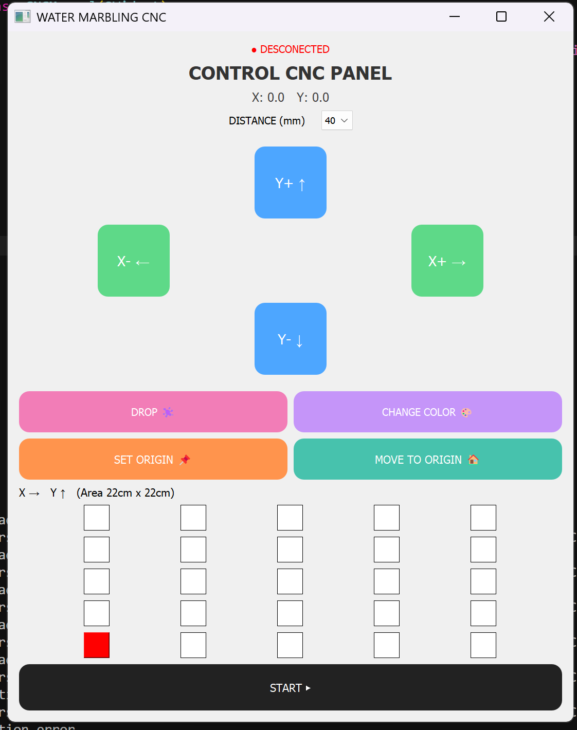
Interface
At the very end of the main loop, motorA.run() and motorB.run() are called to process the motor steps. These functions are "non-blocking," meaning they only move the motors a tiny fraction at a time, which allows the machine to keep listening for new commands even while it is moving. Additionally, the SET_ZERO and HOME commands allow the user to define or return to a starting "origin" point, ensuring that the machine's coordinate system remains accurate throughout the plotting process.
import sys
import serial
import time
from PyQt5.QtWidgets import (
QApplication, QWidget, QPushButton, QVBoxLayout,
QHBoxLayout, QLabel, QComboBox, QGridLayout
)
from PyQt5.QtCore import Qt
class CNCManual(QWidget):
def __init__(self):
super().__init__()
self.serial = None
self.pos_x = 0
self.pos_y = 0
try:
self.serial = serial.Serial("COM12", 115200, timeout=1)
print("✅ Conected")
except:
print("❌ Connection error")
self.puntos = []
self.grid_size = 5
self.current_x = 0
self.current_y = 0
self.initUI()
def initUI(self):
self.setWindowTitle("WATER MARBLING CNC")
self.resize(1100, 1200)
main_layout = QVBoxLayout()
self.estado = QLabel("● DESCONECTED")
self.estado.setAlignment(Qt.AlignCenter)
self.estado.setStyleSheet("font-size:20px; color:red;")
if self.serial:
self.estado.setText("● CONECTED")
self.estado.setStyleSheet("font-size:20px; color:green;")
main_layout.addWidget(self.estado)
titulo = QLabel("CONTROL CNC PANEL")
titulo.setAlignment(Qt.AlignCenter)
titulo.setStyleSheet("font-size:36px; font-weight:bold; color:#333;")
main_layout.addWidget(titulo)
self.label_pos = QLabel("X: 0.0 Y: 0.0")
self.label_pos.setAlignment(Qt.AlignCenter)
self.label_pos.setStyleSheet("font-size:24px; color:#444;")
main_layout.addWidget(self.label_pos)
step_layout = QHBoxLayout()
step_label = QLabel("DISTANCE (mm)")
step_label.setStyleSheet("font-size:20px;")
self.step_box = QComboBox()
self.step_box.addItems(["40", "60", "80", "100"])
self.step_box.setStyleSheet("font-size:18px; padding:6px;")
step_layout.addStretch()
step_layout.addWidget(step_label)
step_layout.addSpacing(20)
step_layout.addWidget(self.step_box)
step_layout.addStretch()
main_layout.addLayout(step_layout)
main_layout.addSpacing(20)
grid = QGridLayout()
btn_up = QPushButton("Y+ ↑")
btn_down = QPushButton("Y- ↓")
btn_left = QPushButton("X- ←")
btn_right = QPushButton("X+ →")
for b in [btn_up, btn_down]:
b.setFixedSize(140, 140)
b.setStyleSheet("""
font-size:28px;
background-color:#4da6ff;
color:white;
border-radius:20px;
""")
for b in [btn_left, btn_right]:
b.setFixedSize(140, 140)
b.setStyleSheet("""
font-size:28px;
background-color:#5ed988;
color:white;
border-radius:20px;
""")
btn_up.clicked.connect(lambda: self.jog(0, 1))
btn_down.clicked.connect(lambda: self.jog(0, -1))
btn_left.clicked.connect(lambda: self.jog(-1, 0))
btn_right.clicked.connect(lambda: self.jog(1, 0))
grid.addWidget(btn_up, 0, 1)
grid.addWidget(btn_left, 1, 0)
grid.addWidget(btn_right, 1, 2)
grid.addWidget(btn_down, 2, 1)
main_layout.addLayout(grid)
main_layout.addSpacing(20)
fila1 = QHBoxLayout()
btn_drop = QPushButton("DROP ")
btn_color = QPushButton("CHANGE COLOR 🎨")
btn_drop.setFixedHeight(80)
btn_color.setFixedHeight(80)
btn_drop.setStyleSheet("""
font-size:20px;
background-color:#f27db7;
color:white;
border-radius:20px;
""")
btn_color.setStyleSheet("""
font-size:20px;
background-color:#c595f9;
color:white;
border-radius:20px;
""")
btn_drop.clicked.connect(self.drop)
btn_color.clicked.connect(self.color)
fila1.addWidget(btn_drop)
fila1.addWidget(btn_color)
main_layout.addLayout(fila1)
fila2 = QHBoxLayout()
btn_setzero = QPushButton("SET ORIGIN 📌")
btn_home = QPushButton("MOVE TO ORIGIN 🏠")
btn_setzero.setFixedHeight(80)
btn_home.setFixedHeight(80)
btn_setzero.setStyleSheet("background:#ff944d; color:white; border-radius:20px;")
btn_home.setStyleSheet("background:#47c2ad; color:white; border-radius:20px;")
btn_setzero.clicked.connect(self.set_zero)
btn_home.clicked.connect(self.home)
fila2.addWidget(btn_setzero)
fila2.addWidget(btn_home)
main_layout.addLayout(fila2)
main_layout.addWidget(QLabel("X → Y ↑ (Area 22cm x 22cm)"))
grid_auto = QGridLayout()
self.grid_botones = []
for i in range(self.grid_size):
fila = []
for j in range(self.grid_size):
btn = QPushButton("")
btn.setFixedSize(50, 50)
btn.clicked.connect(lambda _, x=j, y=i: self.toggle(x, y))
grid_auto.addWidget(btn, self.grid_size - 1 - i, j)
fila.append(btn)
self.grid_botones.append(fila)
main_layout.addLayout(grid_auto)
btn_start = QPushButton("START ▶️")
btn_start.setFixedHeight(90)
btn_start.setStyleSheet("background:#222; color:white; border-radius:20px;")
btn_start.clicked.connect(self.ejecutar)
main_layout.addWidget(btn_start)
self.setLayout(main_layout)
self.show()
self.actualizar_grid()
def enviar(self, cmd):
if self.serial:
self.serial.write((cmd + "\n").encode())
def actualizar_label(self):
self.label_pos.setText(f"X: {self.pos_x:.1f} Y: {self.pos_y:.1f}")
def actualizar_grid(self):
for i in range(self.grid_size):
for j in range(self.grid_size):
if (j, i) == (self.current_x, self.current_y):
self.grid_botones[i][j].setStyleSheet("background:red;")
elif (j, i) in self.puntos:
self.grid_botones[i][j].setStyleSheet("background:#4da6ff;")
else:
self.grid_botones[i][j].setStyleSheet("background:white; border:1px solid black;")
def jog(self, dx, dy):
step = int(self.step_box.currentText())
self.pos_x += dx * step
self.pos_y += dy * step
self.current_x += dx
self.current_y += dy
self.current_x = max(0, min(self.grid_size - 1, self.current_x))
self.current_y = max(0, min(self.grid_size - 1, self.current_y))
self.actualizar_grid()
self.actualizar_label()
self.enviar(f"JOG,{dx*step},{dy*step}")
def drop(self):
self.enviar("DROP")
def color(self):
self.enviar("COLOR")
def set_zero(self):
self.pos_x = 0
self.pos_y = 0
self.current_x = 0
self.current_y = 0
self.actualizar_label()
self.actualizar_grid()
self.enviar("SET_ZERO")
def home(self):
self.pos_x = 0
self.pos_y = 0
self.current_x = 0
self.current_y = 0
self.actualizar_label()
self.actualizar_grid()
self.enviar("HOME")
def toggle(self, x, y):
if (x, y) in self.puntos:
self.puntos.remove((x, y))
else:
self.puntos.append((x, y))
self.actualizar_grid()
def ejecutar(self):
tam_celda = int(self.step_box.currentText())
self.enviar("SET_ZERO")
time.sleep(0.5)
for (x, y) in self.puntos:
target_x = x * tam_celda
target_y = y * tam_celda
self.current_x = x
self.current_y = y
self.actualizar_grid()
self.enviar(f"GOTO,{target_x},{target_y}")
time.sleep(1.2)
self.enviar("DROP")
time.sleep(0.8)
if __name__ == "__main__":
app = QApplication(sys.argv)
ventana = CNCManual()
sys.exit(app.exec_())