Week 12: Mechanical Design, Machine Design
Water Marbling CNC - Grupal Assignment
Introduction
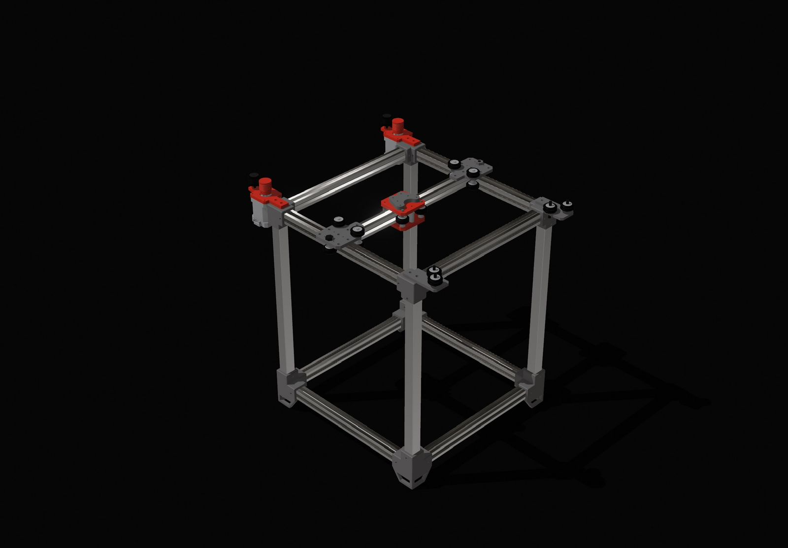
We decided to build a CNC machine specialized in Water Marbling. This technique involves dropping paint onto the surface of thickened water to create patterns, which are then transferred to paper or fabric. Our machine automates the drop placement and the "combing" process to create consistent, complex geometric patterns.
The mechanical motion of our machine is based on the Urumbu 3D concept, adapted to our specific requirements. The design features a 2-axis motion system and a custom toolhead to house the color switching mechanism.
My participation consisted of the electronic design and production, I also did the programming of the code for the motors and I had a brief participation on the toolhad design.
Electronic Production
Design
Schematic
X-axis motor
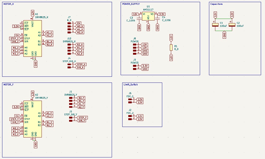
• To control the X-axis, a NEMA 17 motor and the DVR8825 controller were used. In the schematic, the DVR8825 pins are connected to external pins via global labels, in accordance with the DVR8825 pinout.
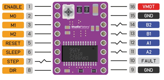
IMAGE FROM-https://www.studiopieters.nl/drv8825-pinout/
Enable and Steps
• It is also important to note that the X and Y motors share four pins: ENABLE, M0, M1, and M2, since they are intended to have the same step size and the same enable signal.
Y-axis motor
• To control the Y-axis, a NEMA 17 motor and the DVR8825 controller were used. In the schematic, the DVR8825 pins are connected to external pins via global labels, in accordance with the DVR8825 pinout. Here it was only used the specific pins for this second driver.
Power Supply
•To regulate and reduce the initial voltage it was used the AMS1117. It requires two capacitors for device stability, one in the input (12V) and one in output (3.3v). Both of 10µF. Then more pins were added, two for 12V and two for GND. It also was added two more pins for 3.3V and GND also were added to the output of the regulator.
Limit Switch
•Two pairs of pins were added to connect two limit switches, designed to stop the CNC’s movement if it exceeds the mechanical limit. When the limit switch is triggered, it interrupts the power supply.
Capacitors
•The capacitors are 100 μF and are connected in parallel. They are configured as decoupling capacitors to filter out voltage spikes and protect the drivers.
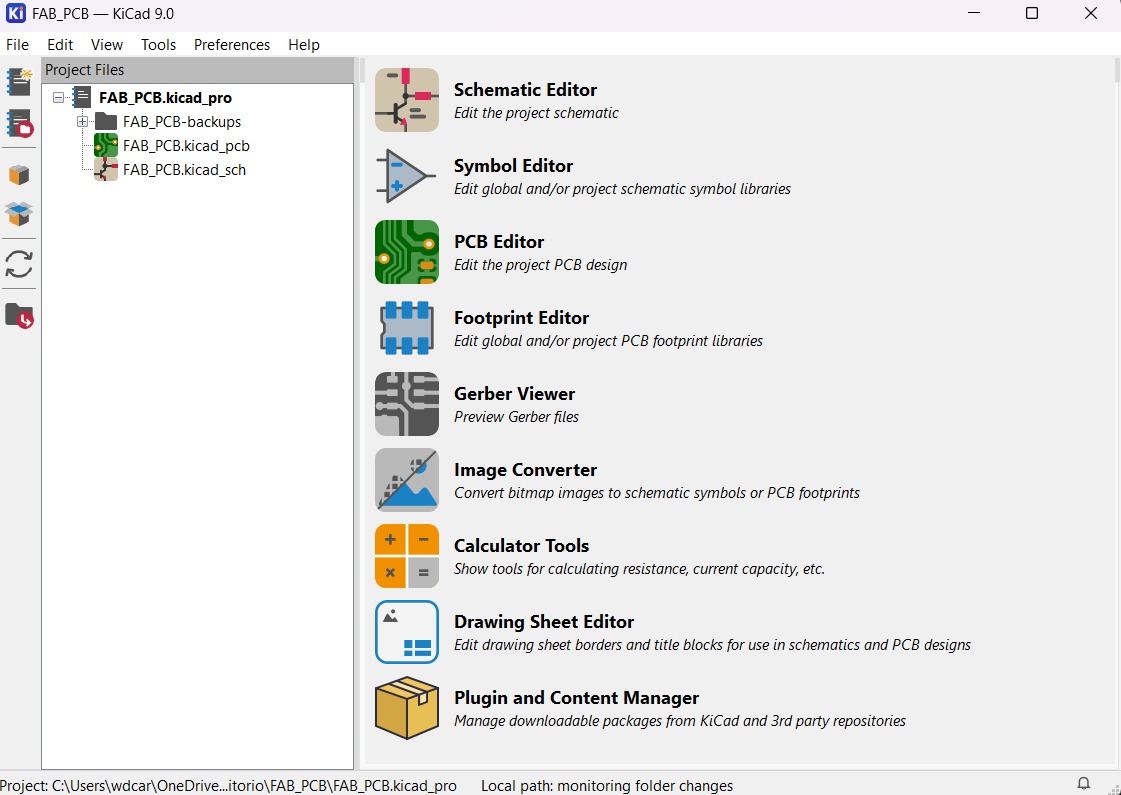
PCB Design
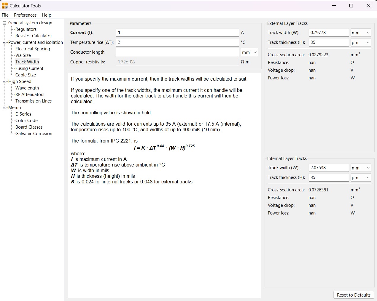
Calculator tool. Before defining the size, it is important to calculate it using the calculator tool given by KiCad. To do that we first have to go to the start menu and open the Calculator tool.Then add the Current (I) and the Temperature rise we are expecting our PCB to have and look fo the result the calculator will give back to us in the right top side. The calculator works by using a formula explained at the bottom.
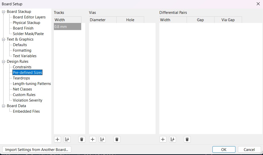
Track thickness. To change the track thickness we must go to the top tool section and click on Track use netclass width. Subsequently, select Edit Pre-defined Sizes.
Inside that section we can add tracks sizes by clicking the + symbol located at the bottom of the window, and in the width section we can change the width of the new track we added. Then we'll just have to click Ok.
Design
After using KiCad’s width calculation tool, two trace widths were selected: 2 mm and 0.8 mm. The 2 mm width was used for the 12 V power supply to ensure the traces were robust. The 0.8 mm width was used for all other traces.
Then using the change side tool, the board was flipped. That action was important because the drivers will be on the underside of the plate.
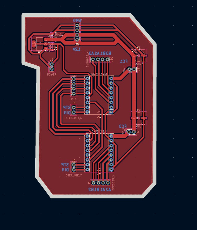
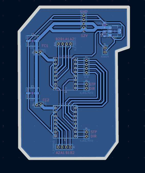
Parameters. • The outline width is 2 mm and its layer is Edge.Cuts. • The track’s width is 0.8 mm- 2 mm and its layer is F.Cu.• The Holes layer is User.1.
Results
Export as SVG
1. First, I changed the border line width to 2 mm because of the tool that will be used later.
2. Then I went to the top left corner and pressed file, after that I selected Fabrication Outputs.
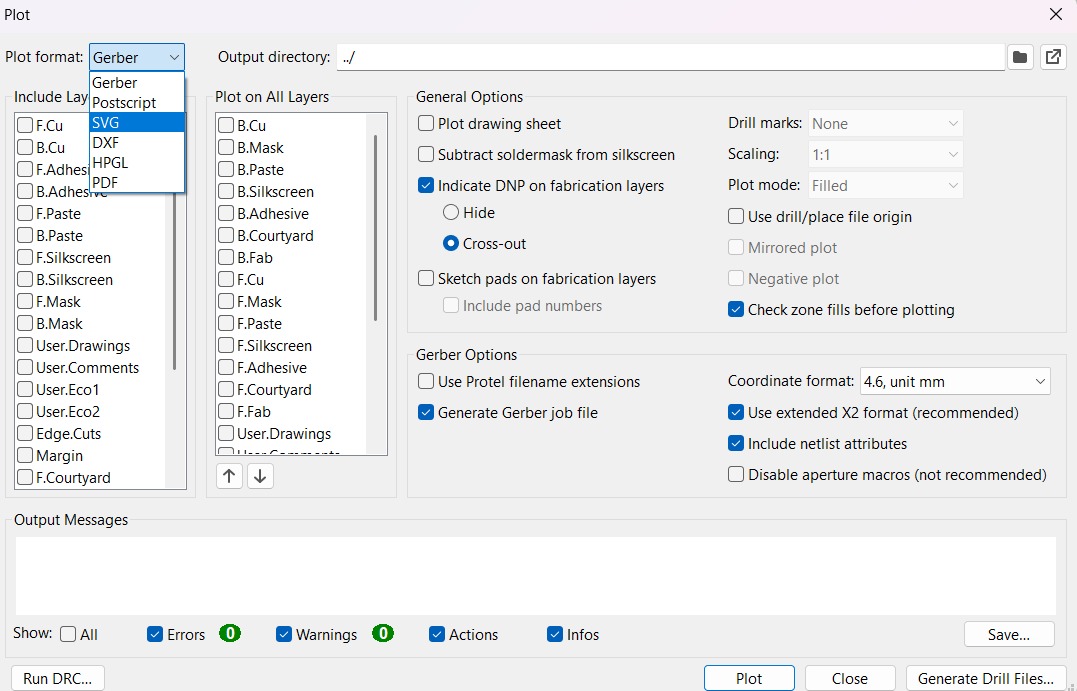
3.In the fabrication outputs we have to select Gerbers. In Gerbers we have to change the plot format to SVG.
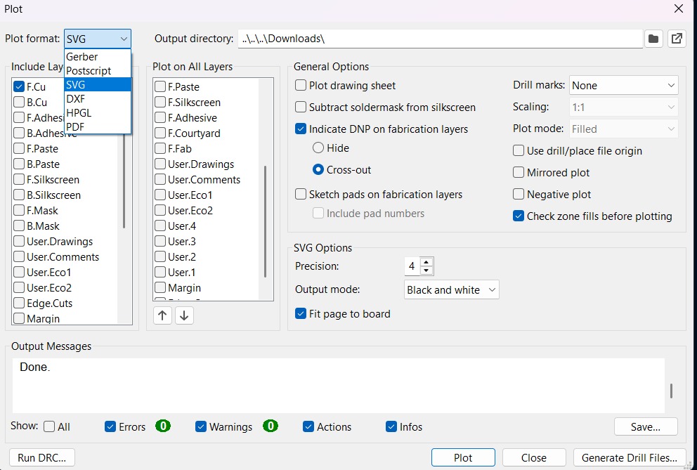
4.Having changed the format to SVG, we have to click on Fit page to board to keep the meassures the way they are in the dessign and select the Output Directory.
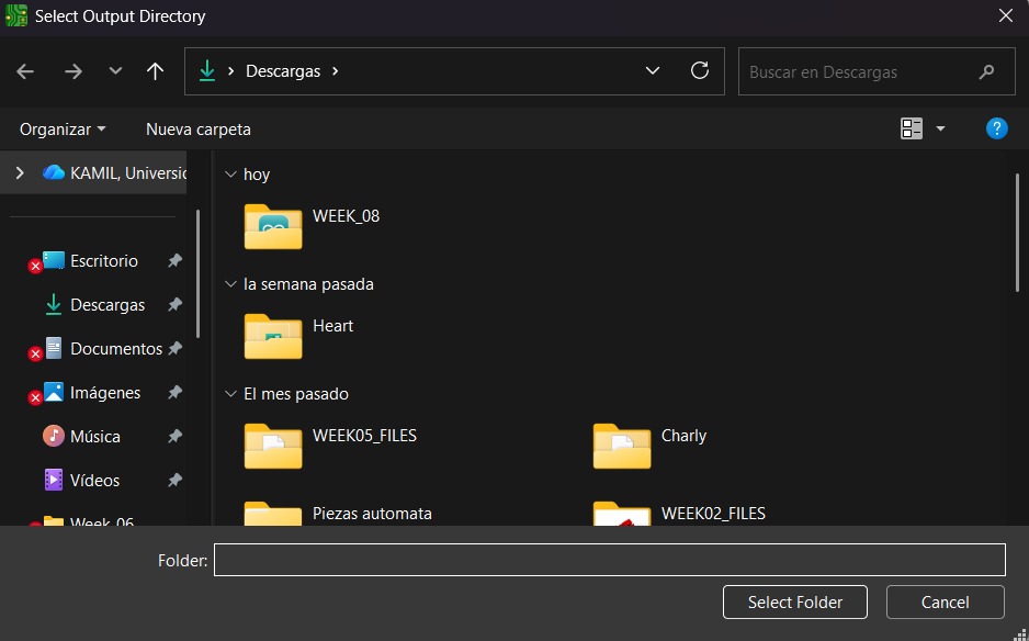
Output Directory To change the Output Directory we have to click on the folder symbol located at the top and select the place in our computer where we want to save our document.
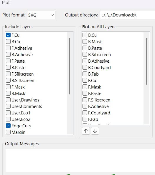
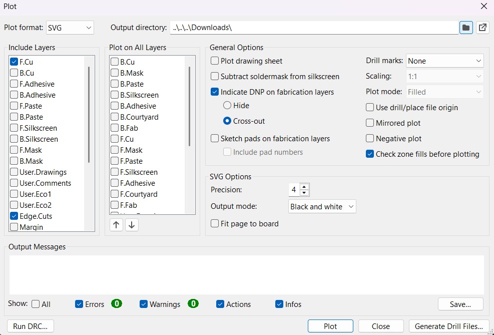
5. Then, we have to select the layers we want to plot.
6. Finally, we have to click on plot and go to the folder where our files are located.
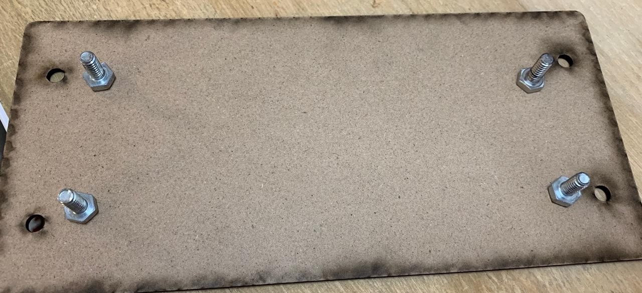
Before Cutting
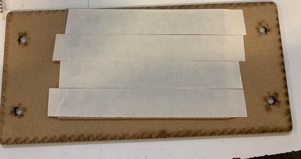
1. First, we have to paste the tape in the back of the copper board.
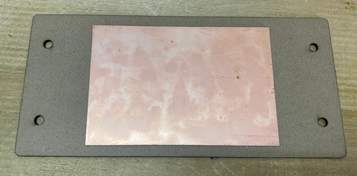
2. Then, we have to paste the copper board to the Sacrifice Bed.
Materials:
Copper Board.
double-sided tape.
Sacrifice Bed. Is an MDF board designed to prevent the SMR-20 from being damaged in the event that the tool drills too deep.
3. Subsequently, we have to place the bed inside the SMR-20. In my case, in my lab, our SMR-20 has a fitting to secure the sacrifice table with screws.
Before Cutting
4. Having secured the bed inside the SMR-20, we have to select the tool for each milling process (Holes, Tracks and Borders).
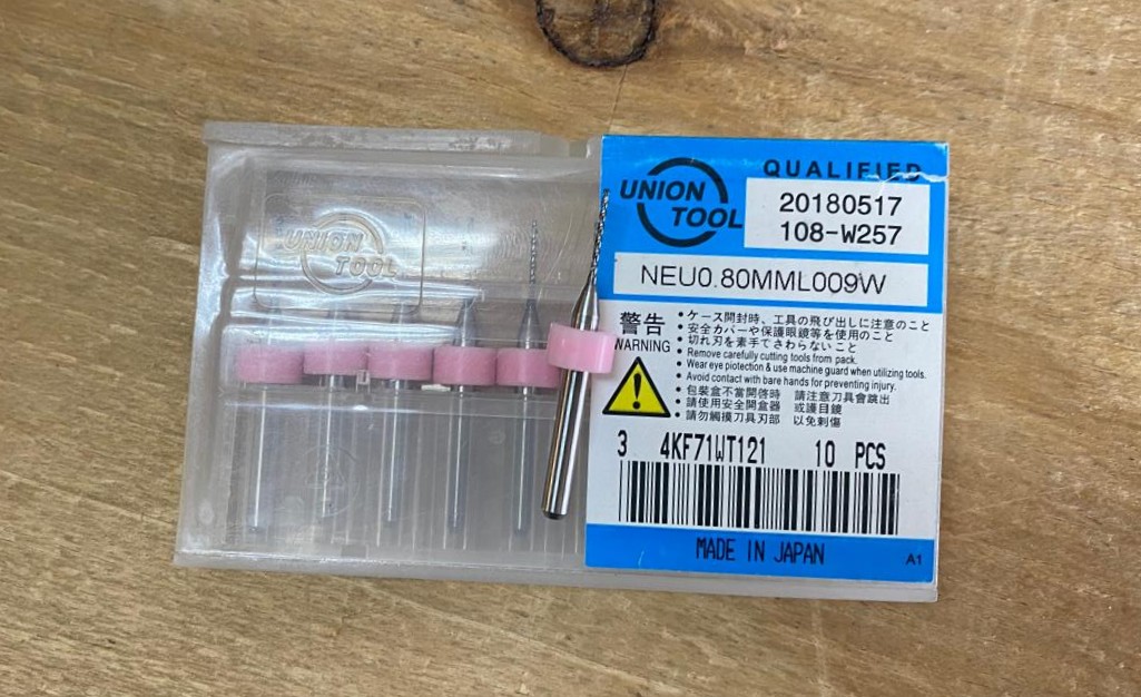
Drilling Tool. This tool is specifically for perforations because of its shape and width. To use it, we must set the speed between 0.1 and 0.5 in order to don't damage it.
Drilling - MODS.
Tool width. 0.8 mm
Speed. 0.5 mm/s
Origin (x,y,z). (0,0,0)
Offset number. 1
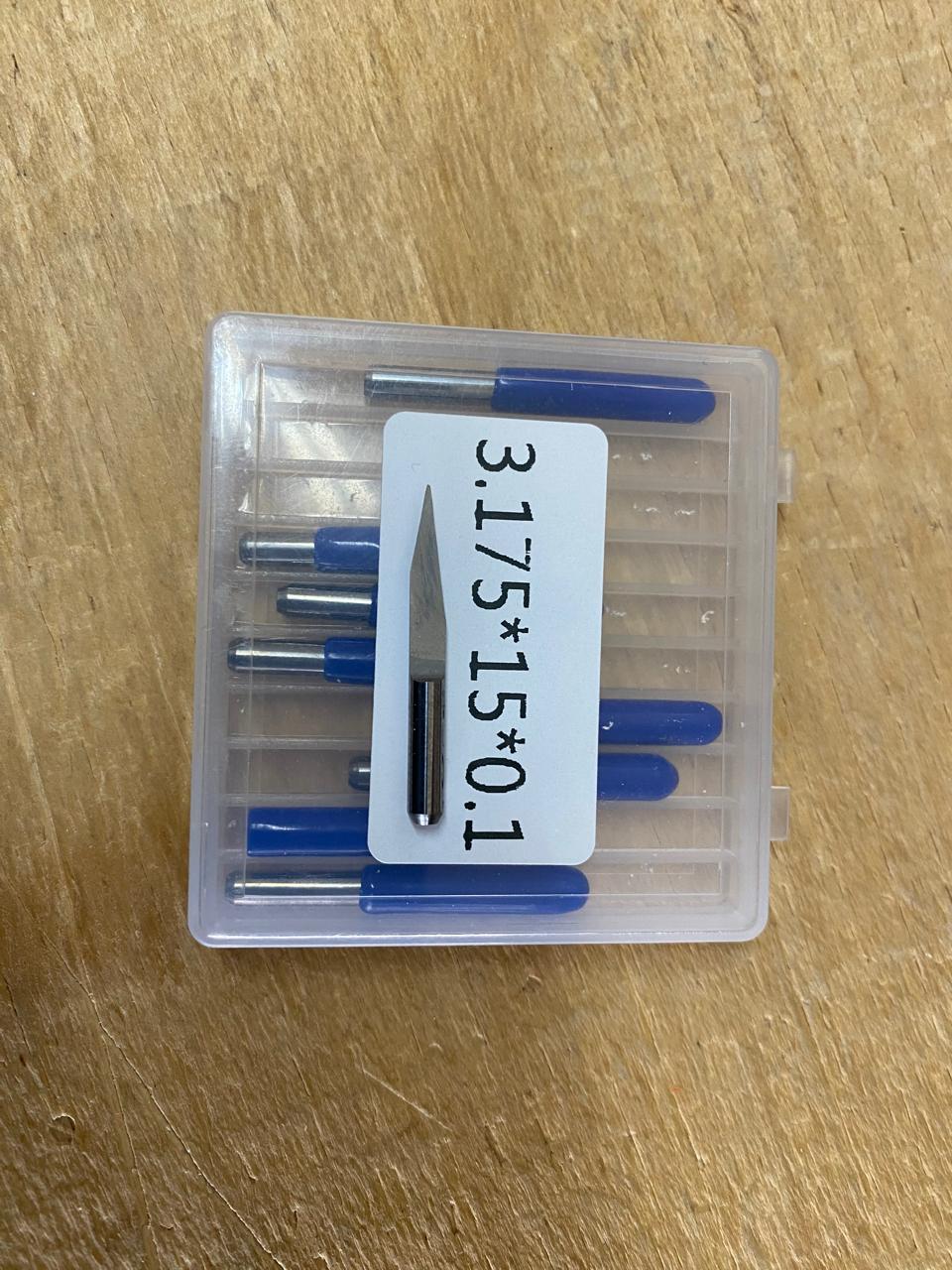
Cutting tool. This tool is specifically designed for traces, as its point is sharp and very thin. The Speed of use can be higher but we must be careful about its deep.
Cutting - MODS.
Tool width. 0.39 mm
Speed. 4 mm/s
Origin (x,y,z). (0,0,0)
Offset number. 3
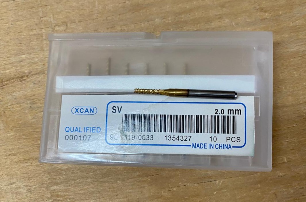
Outline tool. This tool is can be used for the border cutting because of its width, it can also be used for perforation, but the diameter of them will be bigger.
Outline - MODS.
Tool width. 2 mm
Speed. 4 mm/s
Origin (x,y,z). (0,0,0)
Offset number. 1
Cutting
1. We have to connect our computer to the SMR-20 and open VPANEL.
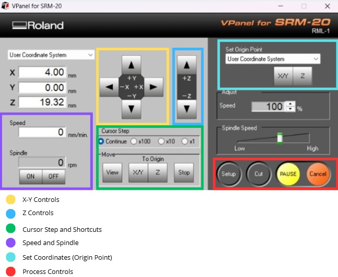
VPANEL.
X-Y Controls. Move the tool in the X-Y axis.
Z Controls.Move the tool in the Z axis.
Cursor Step and Shortcuts. The Step Cursor determines the speed at which the tool moves along all axes; Continue is the smoothest and x1 is the slowest setting, since each click corresponds to a single motor movement. The Shortcuts are to automatically move to an already saved point (Origin Point).
Speed and Spindle. Is to set the speed and to turn on or turn off the the spin of the tool.
Set Coordinates (Origin Point). By clicking the XY or the Z button we can set the Origin Point.
Process Controls. Cut is for adding our code and start the process. Pause, this allows you to pause the process and resume it from where it left off. Stop, stops the process.
Cutting
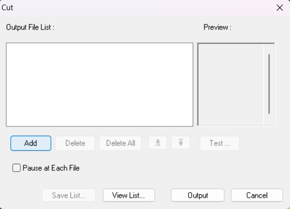
2. Then we have to click on Cut. A window will open, and we should click Add to add our milling code.
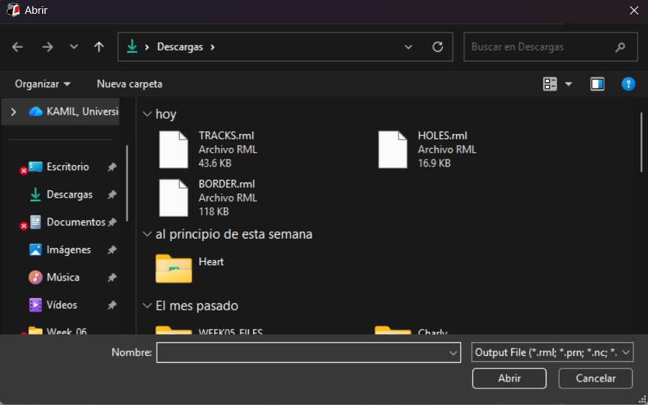
3. Finally we have to click Output and the machine will automatically start to cut.
After Cutting
1. After finishing the cutting, very carefully, we must take out the copper board and remove our PCB.
Design
Schematic
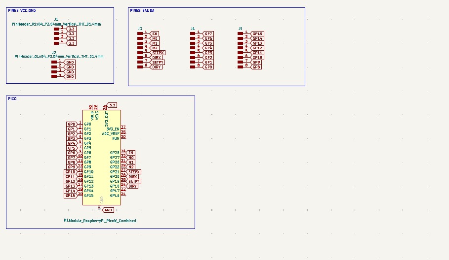
PICO and Power Supply
• For the Pi Pico 2 board, only this component was used, along with external pins connected to the board’s pins via global labels. Since all ground pins are connected internally, ground pins were omitted from the board layout, and four separate ground pins were added instead. Four separate 3.3V pins were also added.
PCB Design
Calculator tool. Before defining the size, it is important to calculate it using the calculator tool given by KiCad. To do that we first have to go to the start menu and open the Calculator tool.Then add the Current (I) and the Temperature rise we are expecting our PCB to have and look fo the result the calculator will give back to us in the right top side. The calculator works by using a formula explained at the bottom.
Track thickness. To change the track thickness we must go to the top tool section and click on Track use netclass width. Subsequently, select Edit Pre-defined Sizes.
Inside that section we can add tracks sizes by clicking the + symbol located at the bottom of the window, and in the width section we can change the width of the new track we added. Then we'll just have to click Ok.
Design
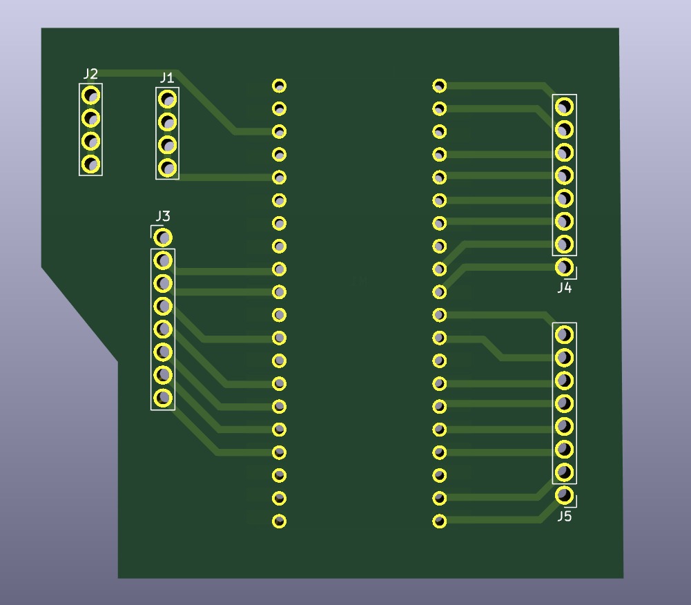
After using KiCad’s calculation tool only one width was selected: 0.8 mm. That width was used for all the traces. Using the change side tool the Raspberry Pi Pico 2 was flipped to put it on the underside of the plate.
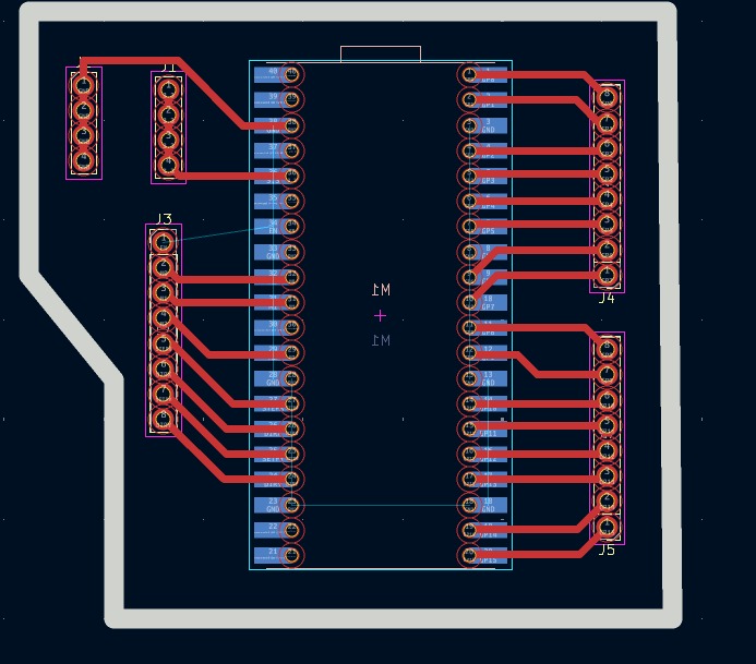
Parameters. • The outline width is 2 mm and its layer is Edge.Cuts. • The track’s width is 0.8 mm and its layer is F.Cu.• The Holes layer is User.1.
Results
Export as SVG
1. First, I changed the border line width to 2 mm because of the tool that will be used later.
2. Then I went to the top left corner and pressed file, after that I selected Fabrication Outputs.
3.In the fabrication outputs we have to select Gerbers. In Gerbers we have to change the plot format to SVG.
4.Having changed the format to SVG, we have to click on Fit page to board to keep the meassures the way they are in the dessign and select the Output Directory.
Output Directory To change the Output Directory we have to click on the folder symbol located at the top and select the place in our computer where we want to save our document.
5. Then, we have to select the layers we want to plot.
6. Finally, we have to click on plot and go to the folder where our files are located.
Before Cutting
1. First, we have to paste the tape in the back of the copper board.
2. Then, we have to paste the copper board to the Sacrifice Bed.
Materials:
Copper Board.
double-sided tape.
Sacrifice Bed. Is an MDF board designed to prevent the SMR-20 from being damaged in the event that the tool drills too deep.
3. Subsequently, we have to place the bed inside the SMR-20. In my case, in my lab, our SMR-20 has a fitting to secure the sacrifice table with screws.
Before Cutting
4. Having secured the bed inside the SMR-20, we have to select the tool for each milling process (Holes, Tracks and Borders).
Drilling Tool. This tool is specifically for perforations because of its shape and width. To use it, we must set the speed between 0.1 and 0.5 in order to don't damage it.
Drilling - MODS.
Tool width. 0.8 mm
Speed. 0.5 mm/s
Origin (x,y,z). (0,0,0)
Offset number. 1
Cutting tool. This tool is specifically designed for traces, as its point is sharp and very thin. The Speed of use can be higher but we must be careful about its deep.
Cutting - MODS.
Tool width. 0.39 mm
Speed. 4 mm/s
Origin (x,y,z). (0,0,0)
Offset number. 3
Outline tool. This tool is can be used for the border cutting because of its width, it can also be used for perforation, but the diameter of them will be bigger.
Outline - MODS.
Tool width. 2 mm
Speed. 4 mm/s
Origin (x,y,z). (0,0,0)
Offset number. 1
Cutting
1. We have to connect our computer to the SMR-20 and open VPANEL.
VPANEL.
X-Y Controls. Move the tool in the X-Y axis.
Z Controls.Move the tool in the Z axis.
Cursor Step and Shortcuts. The Step Cursor determines the speed at which the tool moves along all axes; Continue is the smoothest and x1 is the slowest setting, since each click corresponds to a single motor movement. The Shortcuts are to automatically move to an already saved point (Origin Point).
Speed and Spindle. Is to set the speed and to turn on or turn off the the spin of the tool.
Set Coordinates (Origin Point). By clicking the XY or the Z button we can set the Origin Point.
Process Controls. Cut is for adding our code and start the process. Pause, this allows you to pause the process and resume it from where it left off. Stop, stops the process.
2. Then we have to click on Cut. A window will open, and we should click Add to add our milling code.
3. Finally we have to click Output and the machine will automatically start to cut.
After Cutting
1. After finishing the cutting, very carefully, we must take out the copper board and remove our PCB.
Design
Schematic
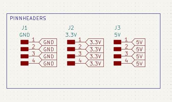
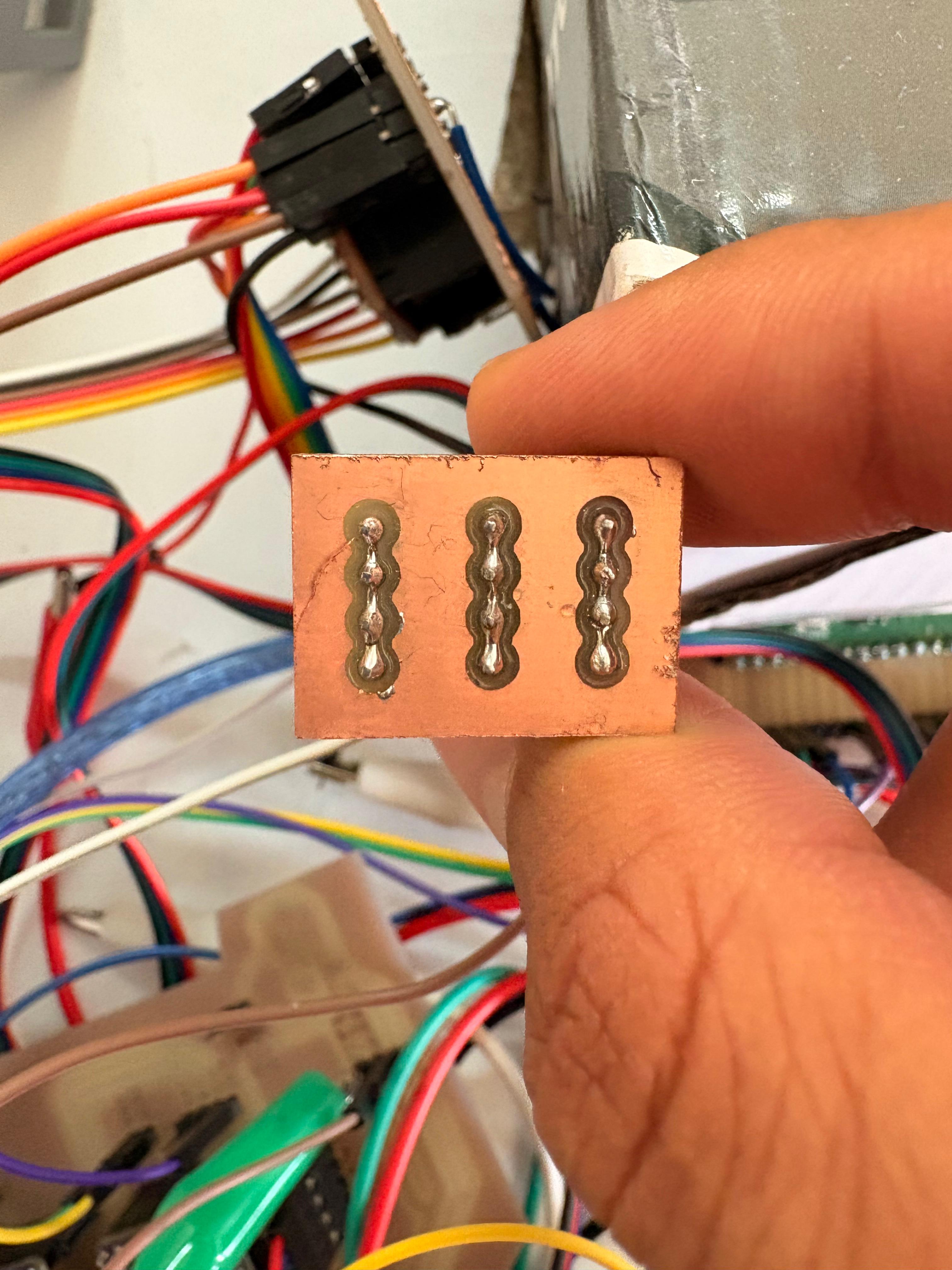
Extra pins
• The extra pins board was created because more GND pins were needed during the process of connecting the modules. The schematic consists of just three columns of four pins connected to each other.
PCB Design
Calculator tool. Before defining the size, it is important to calculate it using the calculator tool given by KiCad. To do that we first have to go to the start menu and open the Calculator tool.Then add the Current (I) and the Temperature rise we are expecting our PCB to have and look fo the result the calculator will give back to us in the right top side. The calculator works by using a formula explained at the bottom.
Track thickness. To change the track thickness we must go to the top tool section and click on Track use netclass width. Subsequently, select Edit Pre-defined Sizes.
Inside that section we can add tracks sizes by clicking the + symbol located at the bottom of the window, and in the width section we can change the width of the new track we added. Then we'll just have to click Ok.
Design
After using KiCad’s calculation tool only one width was selected: 0.8 mm. That width was used for all the traces.
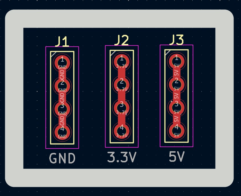
Parameters. • The outline width is 2 mm and its layer is Edge.Cuts. • The track’s width is 0.8 mm and its layer is F.Cu.• The Holes layer is User.1.
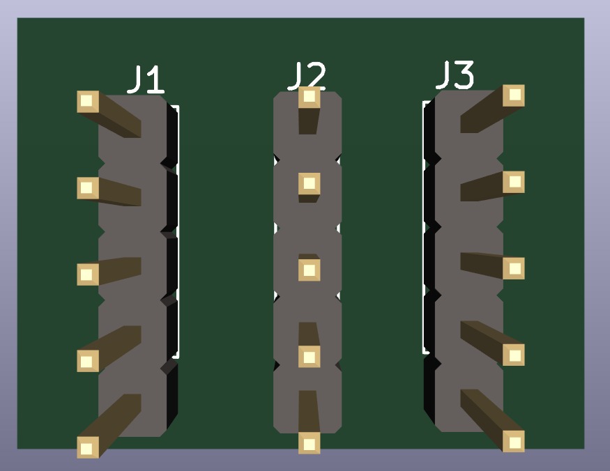
Results
Export as SVG
1. First, I changed the border line width to 2 mm because of the tool that will be used later.
2. Then I went to the top left corner and pressed file, after that I selected Fabrication Outputs.
3.In the fabrication outputs we have to select Gerbers. In Gerbers we have to change the plot format to SVG.
4.Having changed the format to SVG, we have to click on Fit page to board to keep the meassures the way they are in the dessign and select the Output Directory.
Output Directory To change the Output Directory we have to click on the folder symbol located at the top and select the place in our computer where we want to save our document.
5. Then, we have to select the layers we want to plot.
6. Finally, we have to click on plot and go to the folder where our files are located.
Before Cutting
1. First, we have to paste the tape in the back of the copper board.
2. Then, we have to paste the copper board to the Sacrifice Bed.
Materials:
Copper Board.
double-sided tape.
Sacrifice Bed. Is an MDF board designed to prevent the SMR-20 from being damaged in the event that the tool drills too deep.
3. Subsequently, we have to place the bed inside the SMR-20. In my case, in my lab, our SMR-20 has a fitting to secure the sacrifice table with screws.
Before Cutting
4. Having secured the bed inside the SMR-20, we have to select the tool for each milling process (Holes, Tracks and Borders).
Drilling Tool. This tool is specifically for perforations because of its shape and width. To use it, we must set the speed between 0.1 and 0.5 in order to don't damage it.
Drilling - MODS.
Tool width. 0.8 mm
Speed. 0.5 mm/s
Origin (x,y,z). (0,0,0)
Offset number. 1
Cutting tool. This tool is specifically designed for traces, as its point is sharp and very thin. The Speed of use can be higher but we must be careful about its deep.
Cutting - MODS.
Tool width. 0.39 mm
Speed. 4 mm/s
Origin (x,y,z). (0,0,0)
Offset number. 3
Outline tool. This tool is can be used for the border cutting because of its width, it can also be used for perforation, but the diameter of them will be bigger.
Outline - MODS.
Tool width. 2 mm
Speed. 4 mm/s
Origin (x,y,z). (0,0,0)
Offset number. 1
Cutting
1. We have to connect our computer to the SMR-20 and open VPANEL.
VPANEL.
X-Y Controls. Move the tool in the X-Y axis.
Z Controls.Move the tool in the Z axis.
Cursor Step and Shortcuts. The Step Cursor determines the speed at which the tool moves along all axes; Continue is the smoothest and x1 is the slowest setting, since each click corresponds to a single motor movement. The Shortcuts are to automatically move to an already saved point (Origin Point).
Speed and Spindle. Is to set the speed and to turn on or turn off the the spin of the tool.
Set Coordinates (Origin Point). By clicking the XY or the Z button we can set the Origin Point.
Process Controls. Cut is for adding our code and start the process. Pause, this allows you to pause the process and resume it from where it left off. Stop, stops the process.
2. Then we have to click on Cut. A window will open, and we should click Add to add our milling code.
3. Finally we have to click Output and the machine will automatically start to cut.
After Cutting
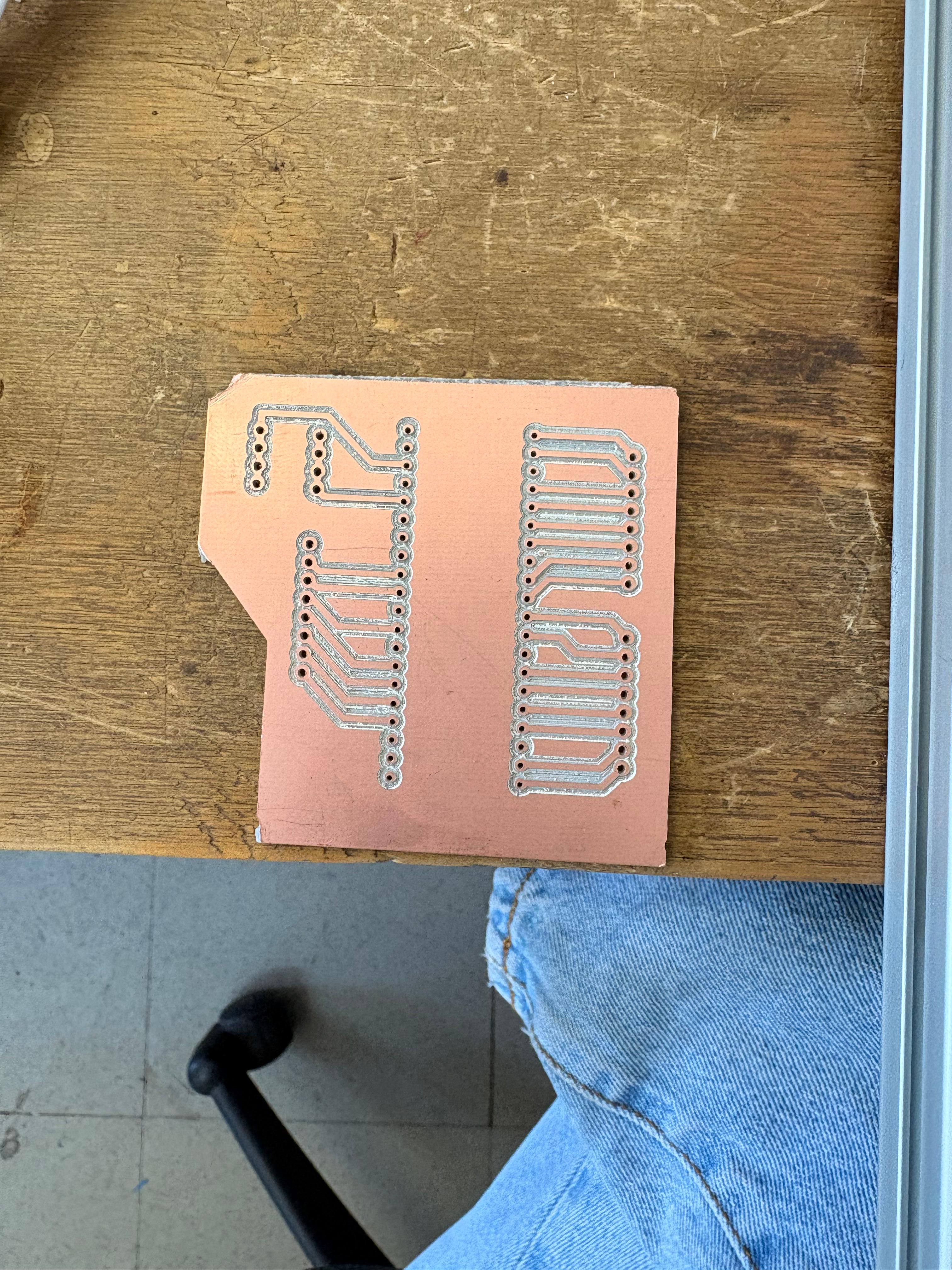
1. After finishing the cutting, very carefully, we must take out the copper board and remove our PCB.
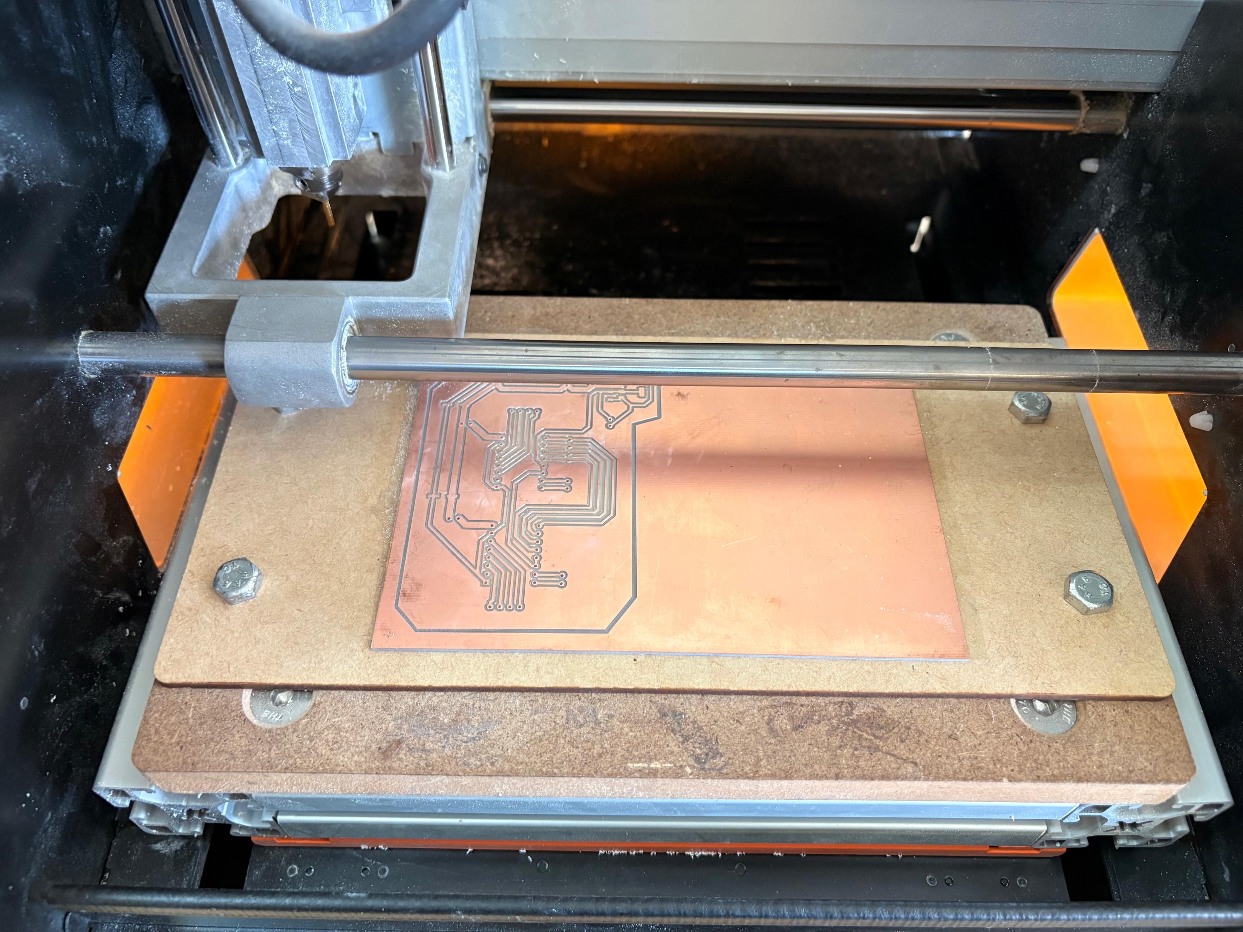
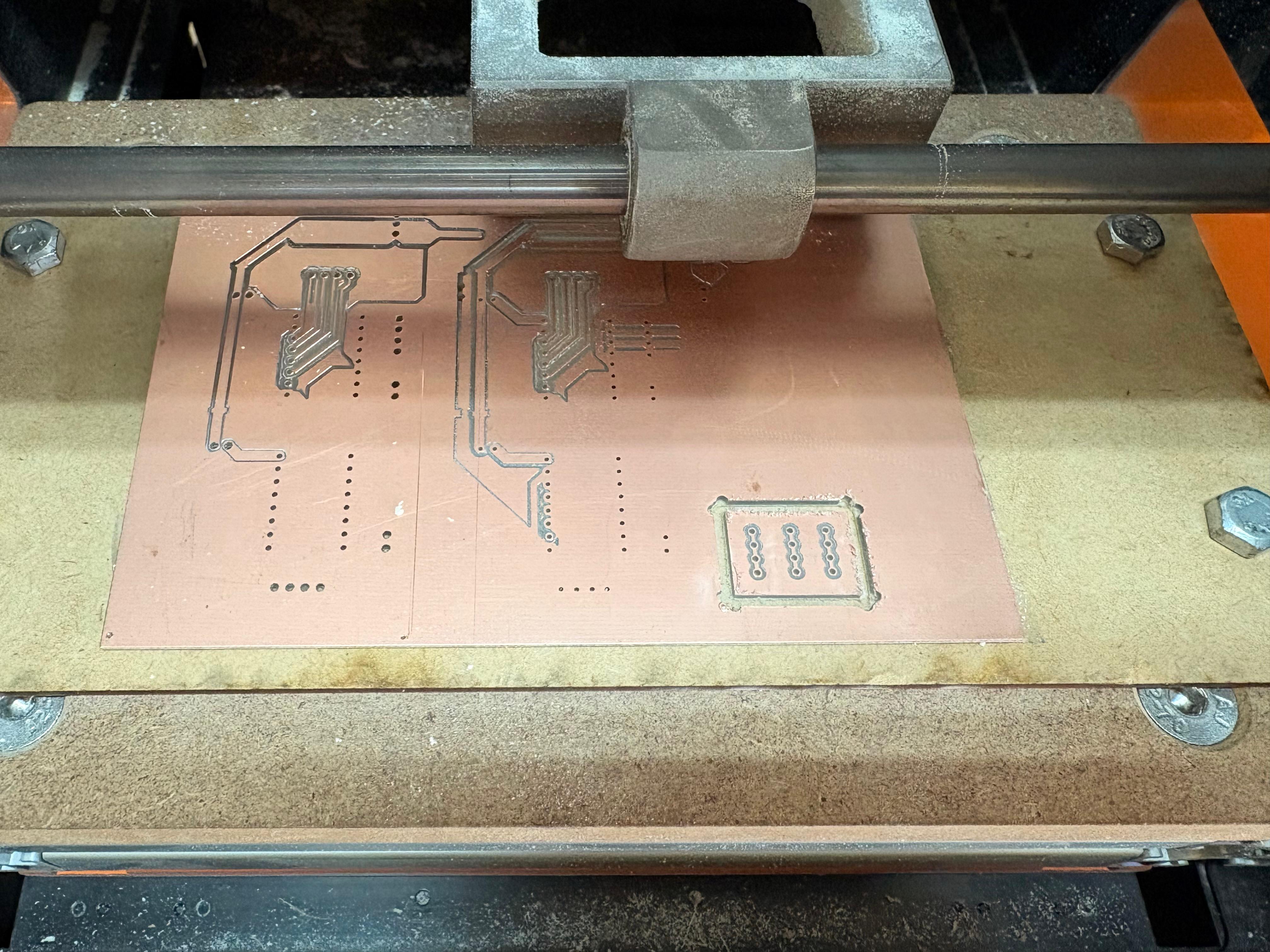
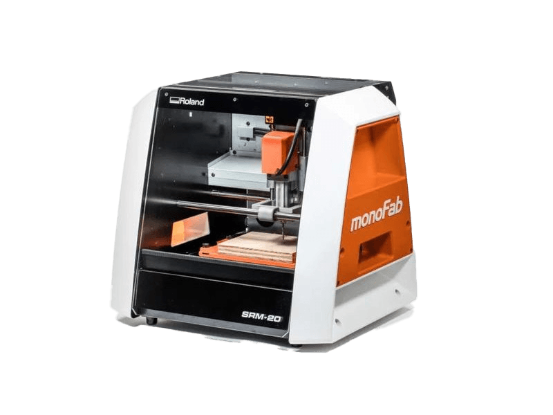
Roland SRM-20
The tool used for cutting the boards is the Roland SRM-20. Is a compact CNC desktop milling machine used for prototyping, PCB milling, and small mechanical parts. It removes material using rotating cutting tools.
Work area: 203.2 × 152.4 × 60.5 mm
Table size: 232.2 × 156.6 mm
Spindle speed: 3,000 – 7,000 rpm
Feed rate: 6 – 1800 mm/min
Mechanical resolution: ~0.000998 mm/step
Max workpiece weight: 2 kg
Control interface: USB (RML-1 or NC code)
Soldering
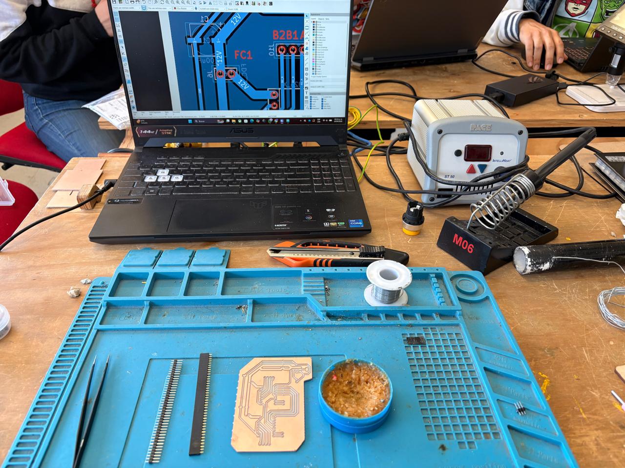
1. To solder, we first need to set up our workspace and gather the necessary tools.
Necessary tools
- Soldering station
- Flux
- Soldering Tin
- Desoldering mesh
- Silicone Tablecloth
Components
- Pinheaders
- 2 10μF smd Capacitors
- 2 100μF smd Capacitors
- 1 AMS 1117
- 1 Heat sink
Soldering
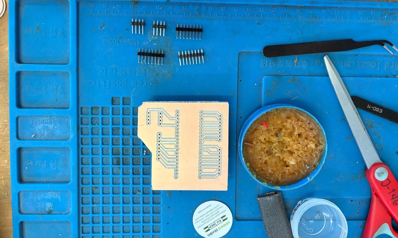
2. First, we need to apply flux to our PCB so that the solder adheres better.
Soldering
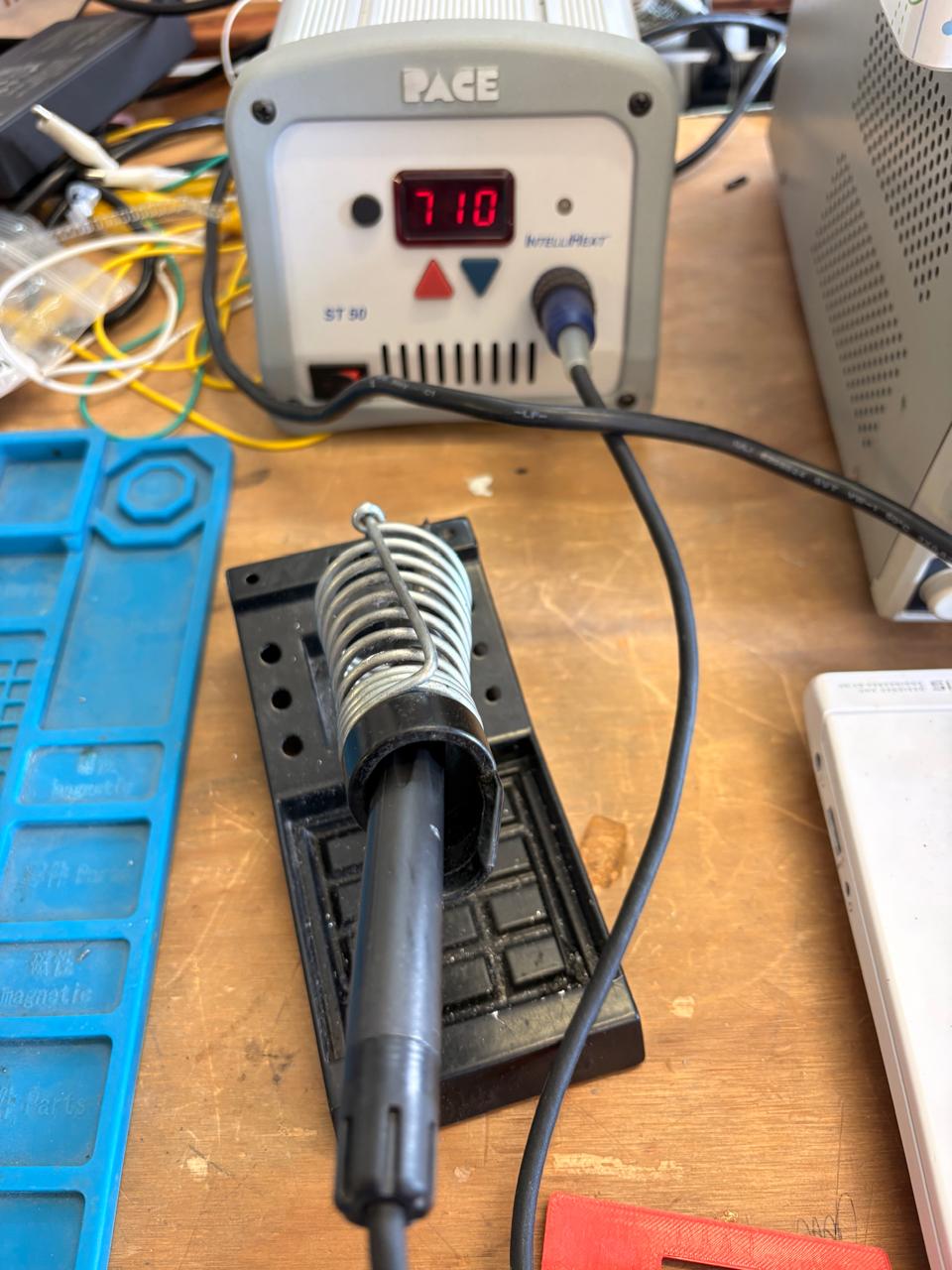
3. Then, we have to turn on the soldering station and set the temperature. To solder tin it is recomendable to place the temperature above 300 °C (572 °F). I will use 375 °C (710 °F) because that works good with my materials.
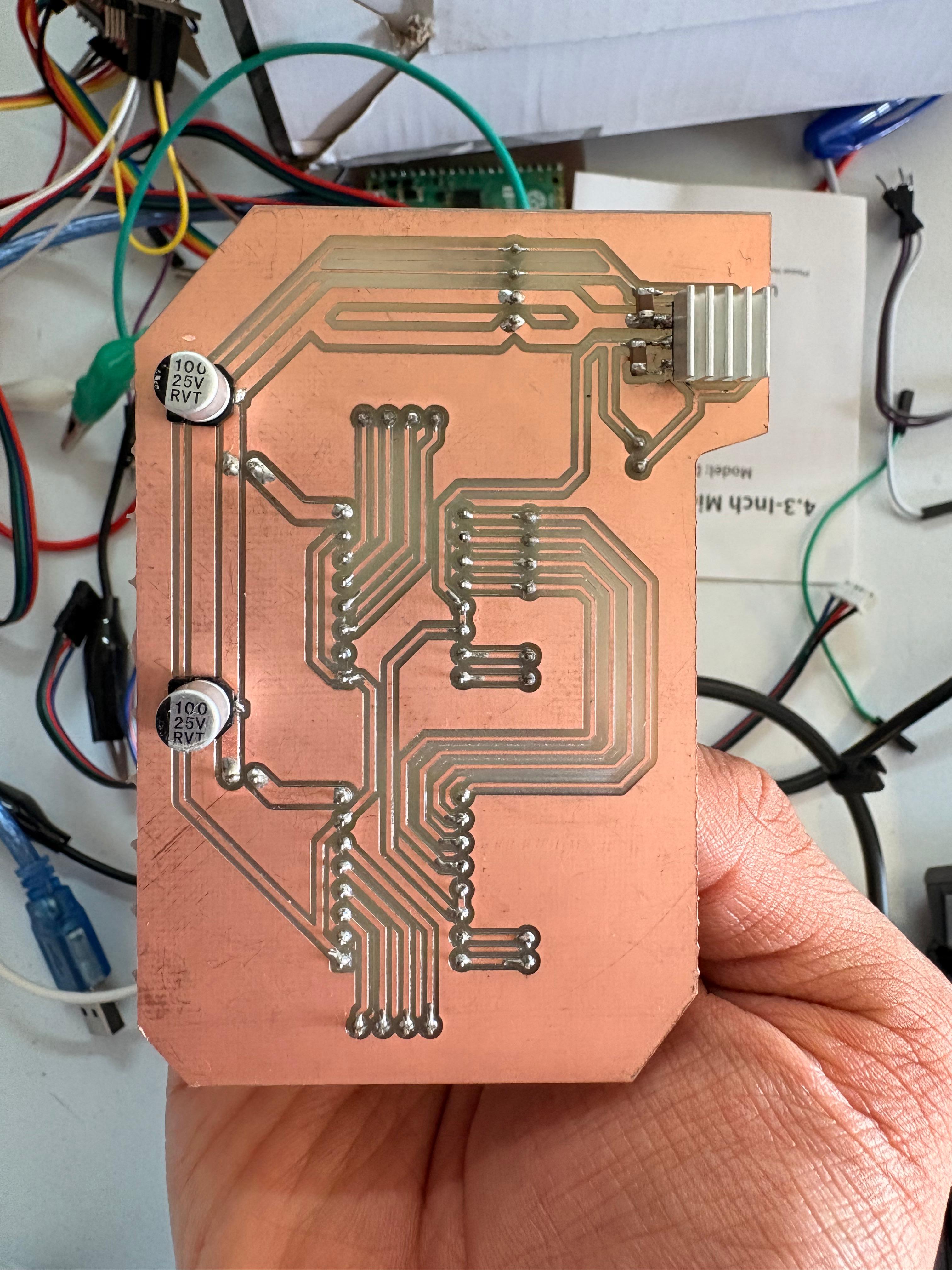
Results
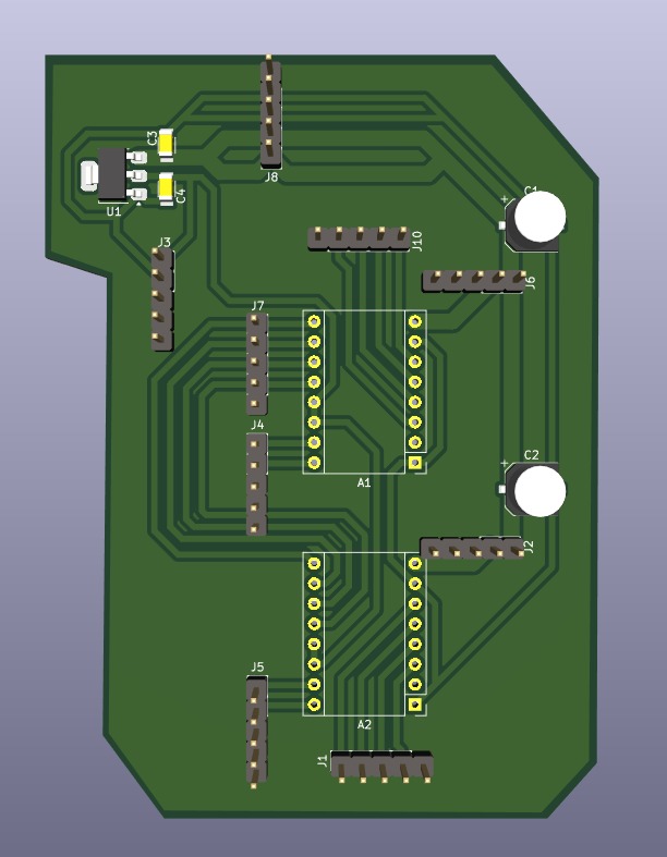
CNC Shield
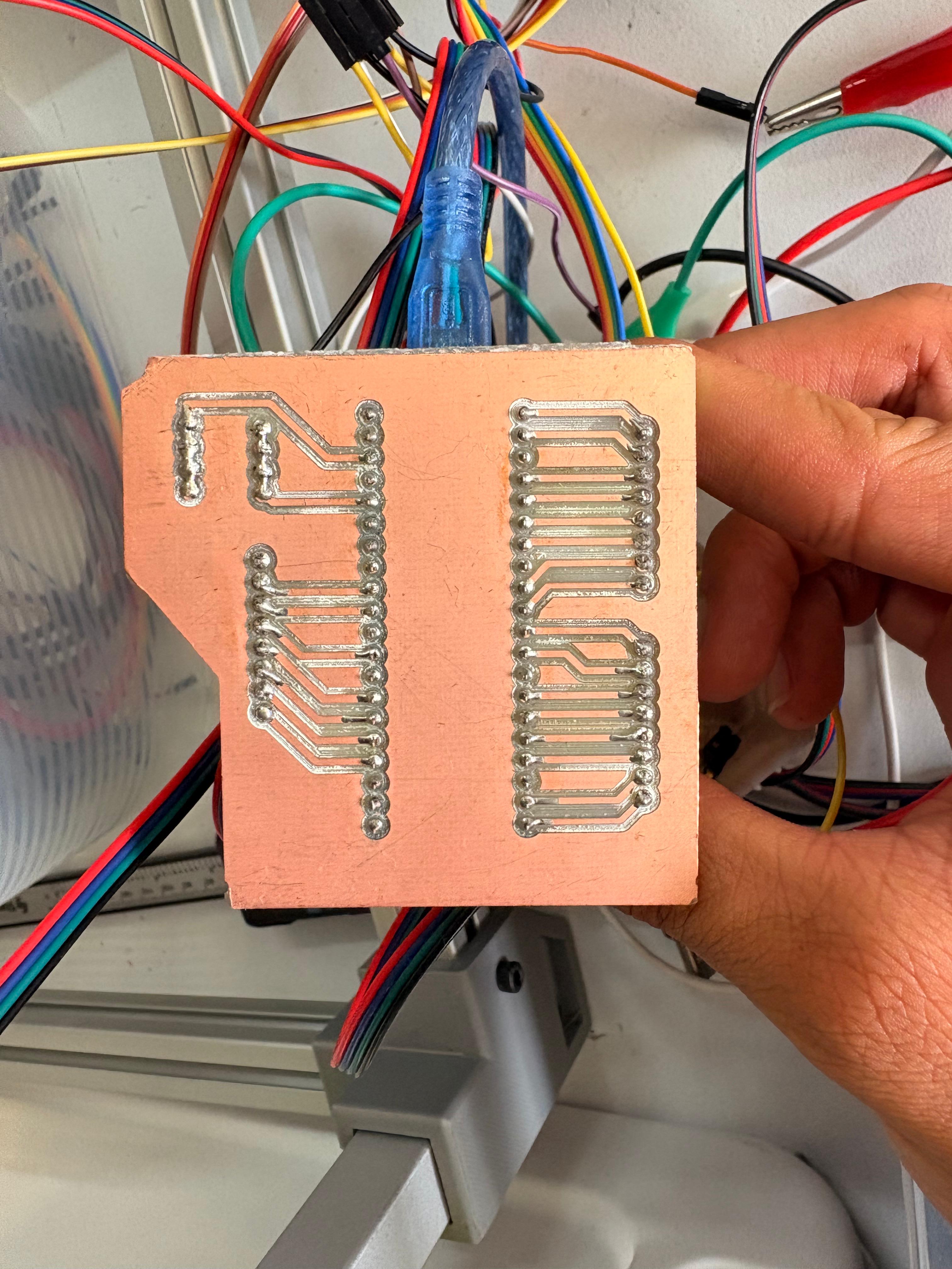
Raspberry Pi Pico 2
Extra Pins
Raspberry Pi Pico 2
Extra Pins
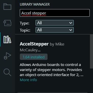
AccelStepper Library
To set the steps, we first need to install the library in Arduino. For that we have to go to the Library Manager and write AccelStepper, then intall the library named like that.
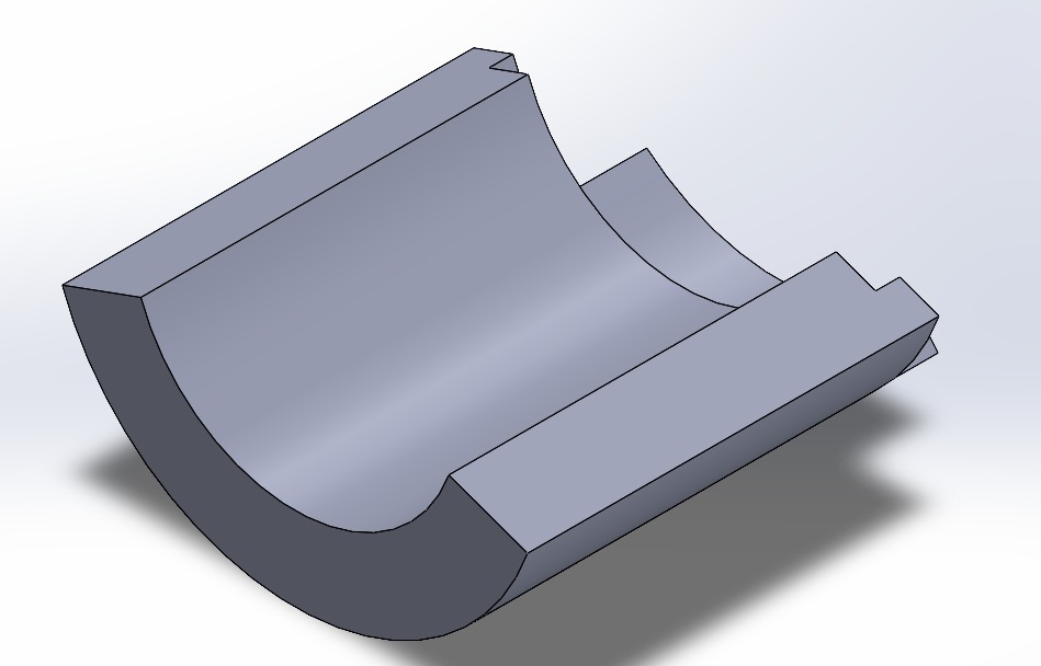
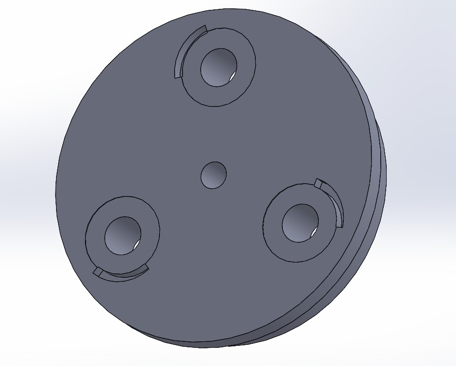
Toolhead
In this part, I just made a few changes and added some parts, such as the brackets for each drip; I also modified the carousel and made some structural changes to make it more sturdy.
Learning outcomes
This week I learned a lot about how a CNC works. I learned how to use an 8825 driver and how to build a shield by incorporating capacitors, a regulator, and the drivers. I also learned about the benefits of modular designs, which make it easier to organize an electronic layout. I also learned how to program a stepper motor and about the CoreXY system, which is the motion mechanism of our CNC.
The opportunities I see for improving my design include making the PCB smaller and incorporating a space in the CNC structure to hold the boards. I would also like to modify the tool head mechanism to make it more robust and durable.