This week we tackled the "make something big" challenge. Our team designed and fabricated a large-scale structure using CNC machining. My role focused on the structural assembly and the logic design for the color-switching mechanism.
Group Assignment
Characterizing the CNC machine (feeds, speeds, and toolpath strategies).
Design Mechanical Integration
One of the main challenges was ensuring the physical integrity of the piece through precise joinery and assembly logic.
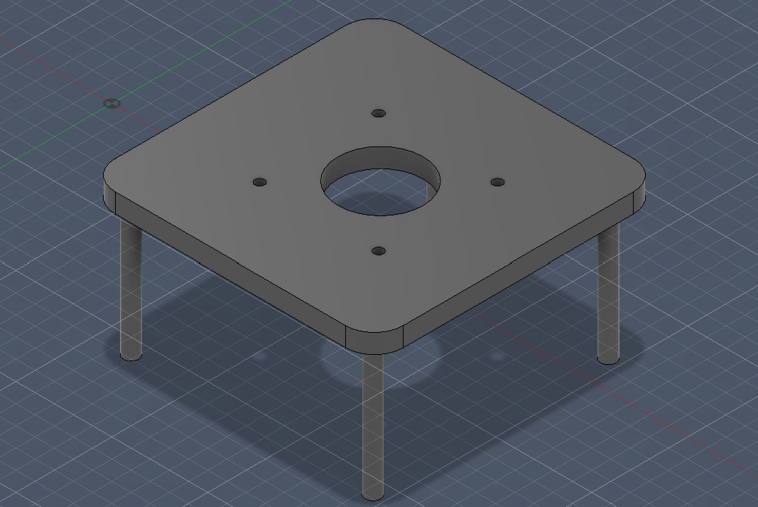
Vertical Drive Mount
As part of the development of the CNC head, a step motor was integrated by designing a custom support. This part allows the top mount of the engine, positioning the shaft vertically downward to optimize motion transmission.
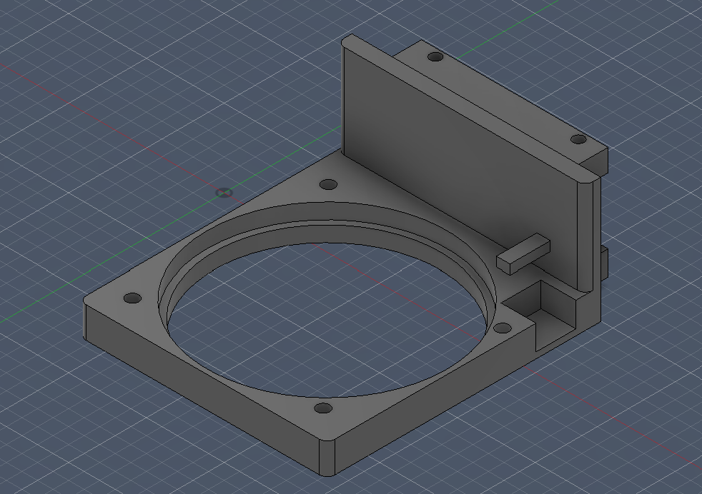
Multi-Stage Dispensing Mount
The next step was the development of a multifunctional support designed to house the stepper engine, the three-drop system and a secondary servomotor responsible for activating the mechanism at source. The geometry of the part was optimized to ensure free rotation of the assembly, avoiding any mechanical interference with the main motor.
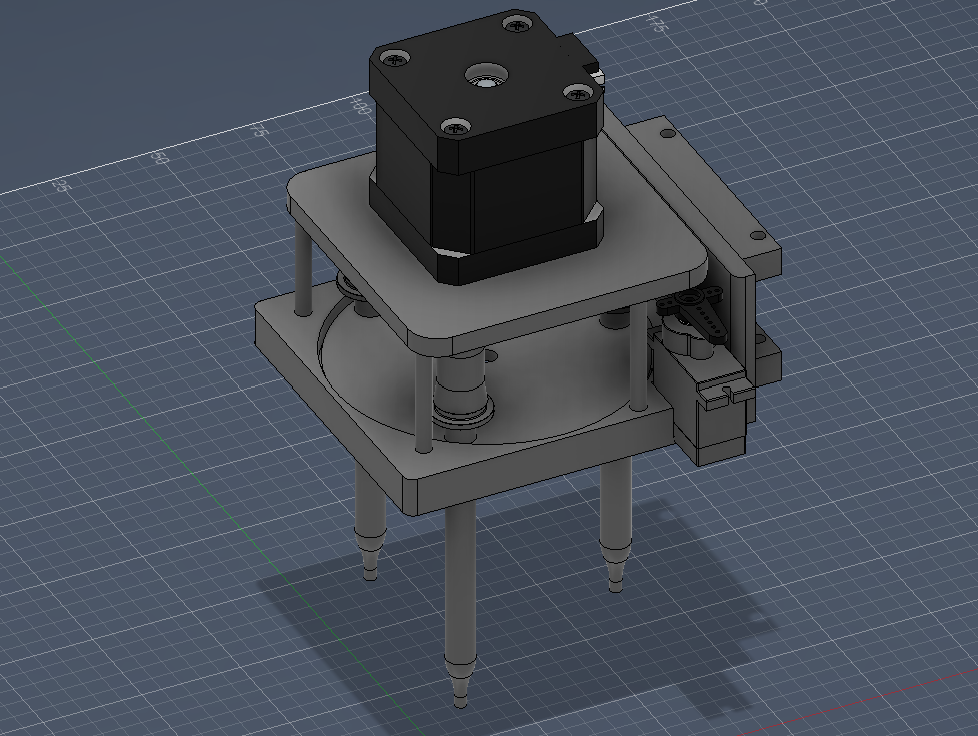
Compact Fluid Control Hub
In the 3D display, you can see the final integration of the components: the step motor, the secondary actuator and the drip system on their support. The assembly was designed to be anchored by a back plate directly to the top structure of the CNC. However, after implementation, it was identified that the excess volume of the head significantly reduced the useful work area, limiting the vertical path to the fluid container.
Structural Fabrication & Machining System Design
I designed the interactive logic for the color-switching feature of the prototype.
PTR Axis Support
For the integration of the structural frame, the PTR (Rectangular Tube Tip) profiles were cut. This process required precise marking and the use of high-speed drills to ensure the perpendicularity of the holes, thus allowing for a gap-free mechanical assembly aligned with the CNC axes.
Standardized Mounting Rail
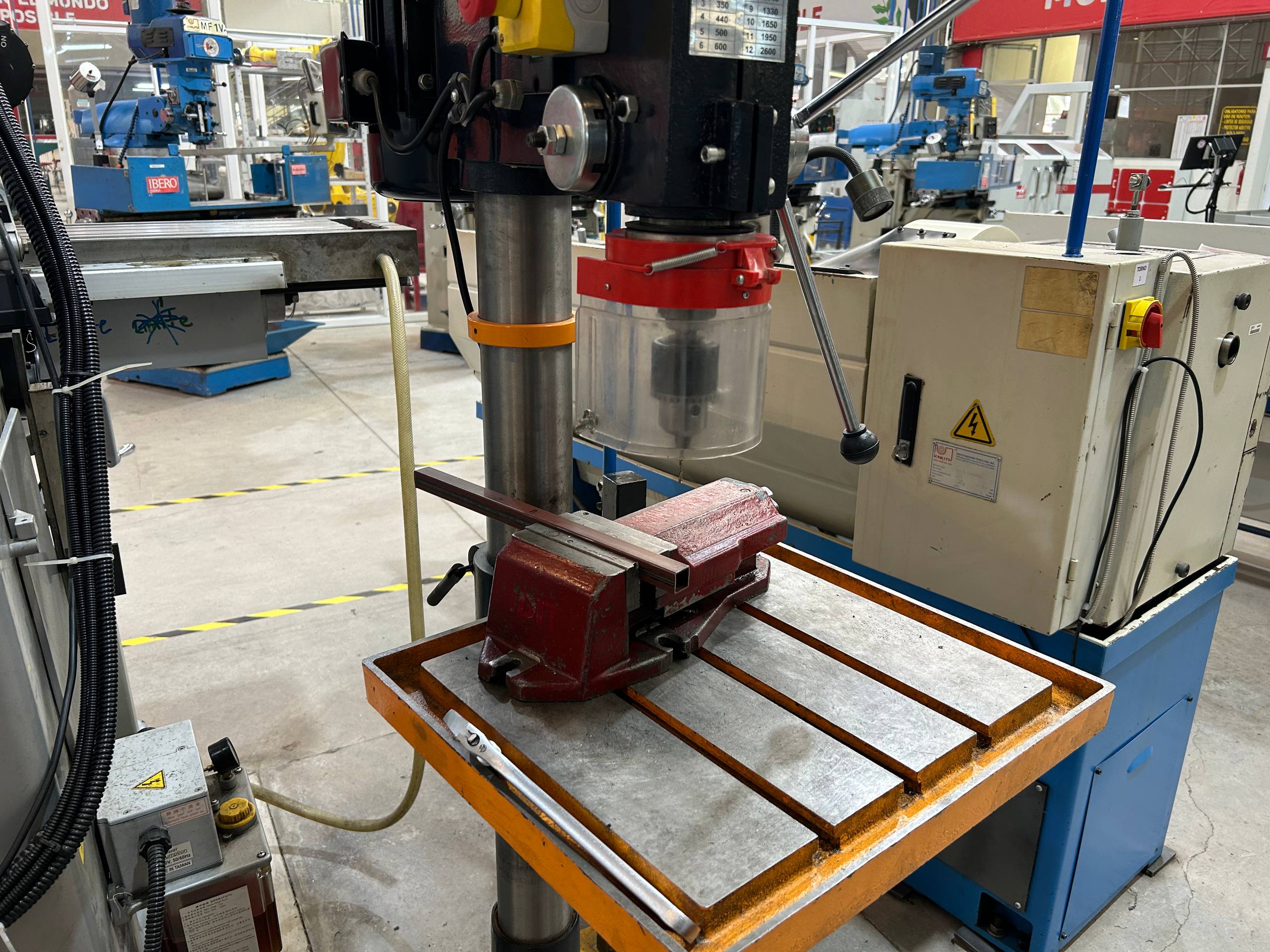
To ensure positioning accuracy in the chassis, PTR profiles were cut using a bench drill. In order to ensure repeatability of the process and avoid vibrations or displacements, the material was rigidly fixed by means of a coordinate press. A series of four drillings was executed using a high-speed steel drill bit (2.5 mm), maintaining a constant feed rate to obtain clean and no scraping finishes.
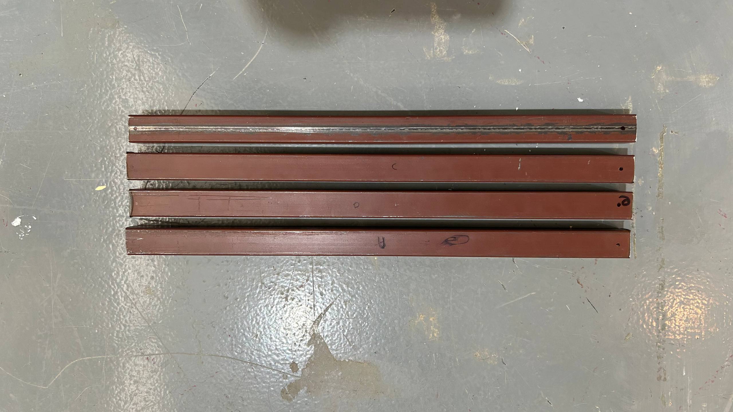
Validated Finish Profile
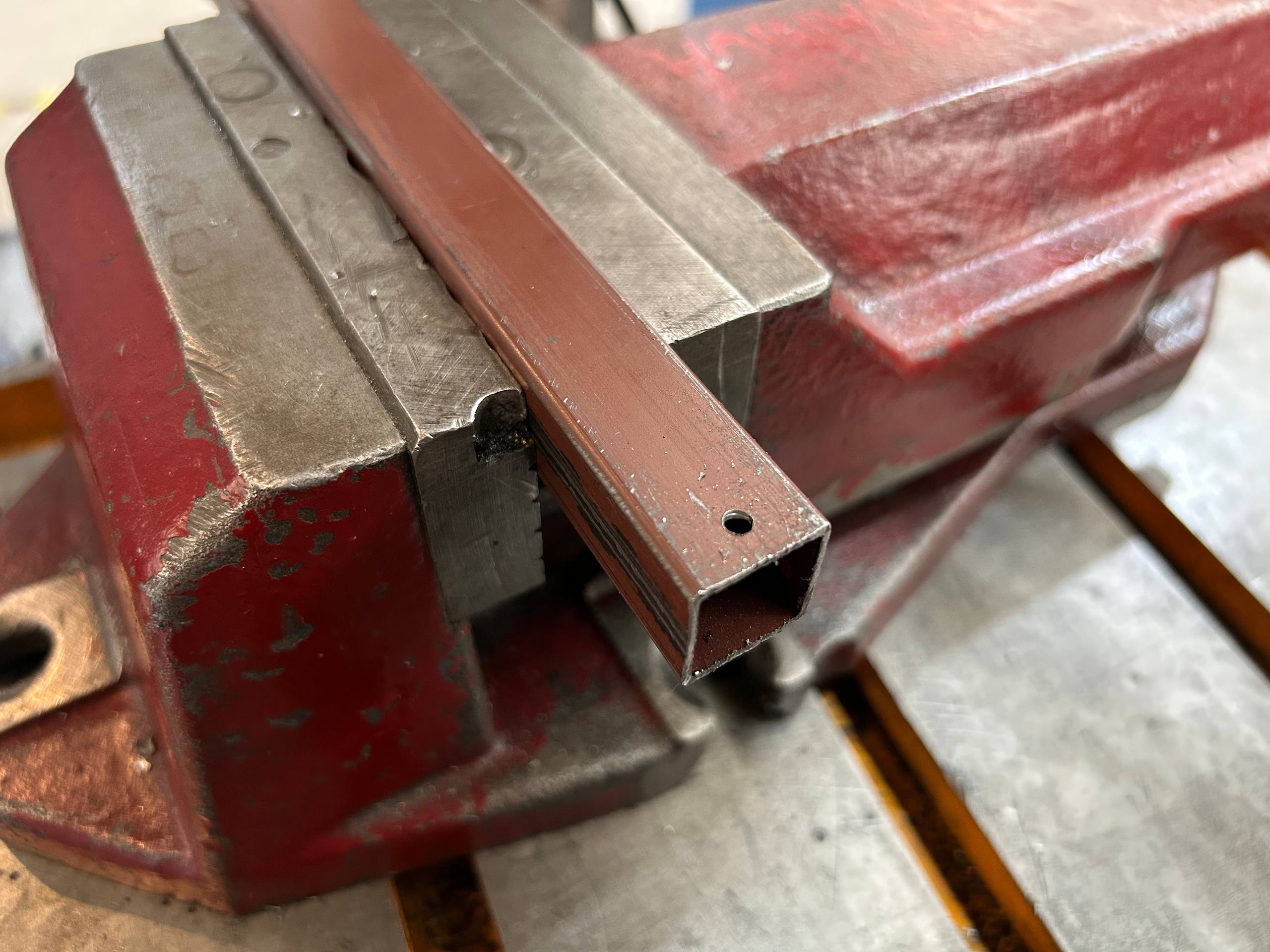
The image shows the final result of the shearing operation on the PTR profiles. The cleanliness of the edges and the absence of significant gouges can be verified, indicating an efficient cutting process with the 2.5 mm drill bit, meeting the positional tolerances required for subsequent assembly.
Calibrated Thread Expansion
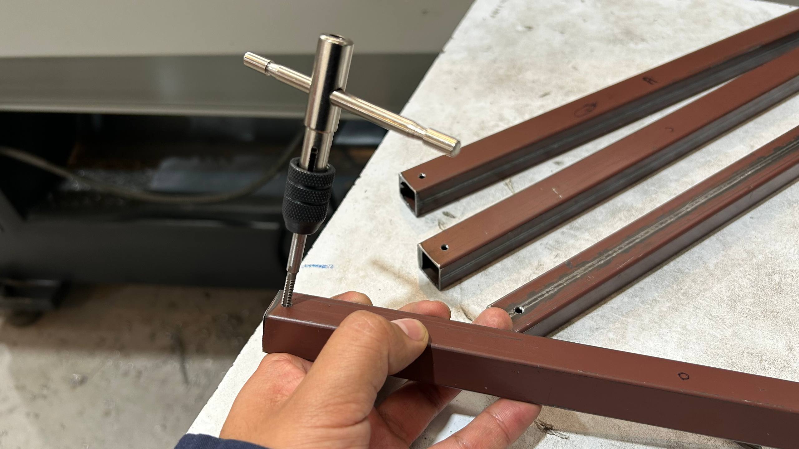
Due to interference in the diameter of the passing rod, the fixing screw could not pass through the structural profile. To solve this, a rework was carried out using a larger machel to expand the internal thread. This operation made it possible to correct the barrel tolerance, ensuring the free passage of the screw and ensuring a firm anchorage between the components
Calibrated Length Profile
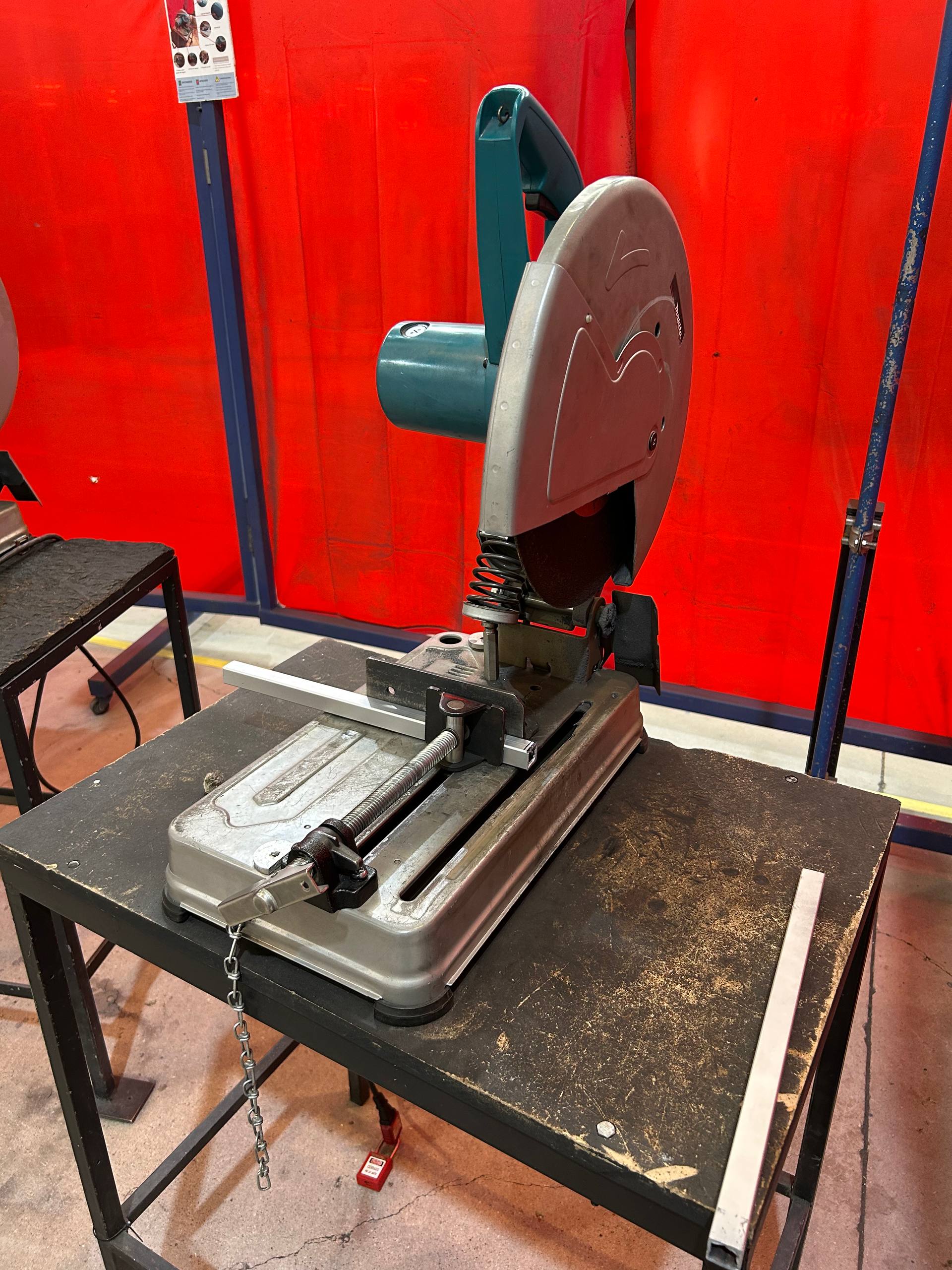
As the final step of the mechanical adjustment, a correction was made in the length of the PTR profile. After identifying an excess of approximately 3 mm affecting the coupling, precision drawing and cutting were carried out using a bench saw. This roughing process made it possible to reach the exact required level, ensuring an airtight fit and alignment with the rest of the CNC structure
Fluid Parameter OptimizationProcess Documentation
Detailed documentation of the assembly process and structural testing.
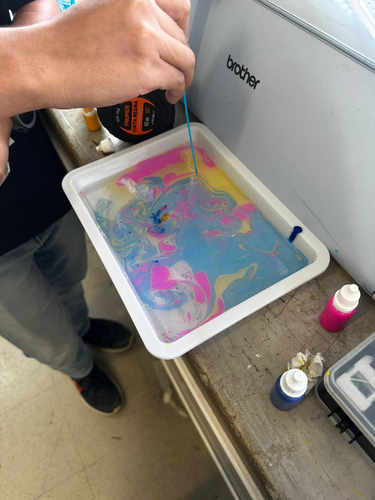
Fluid Dynamics & Dispersion Calibration
To determine the optimal height of the drip system, a calibration phase was performed using manual measuring instruments and pigment samples. After several experimental tests, it was concluded that height was not a determining factor for accuracy, but for dynamic dispersion of the fluid. The objective changed from seeking a static drop to encouraging dispersion that facilitates color mixing. Also, the exact dosage of drops per color was quantified to ensure a visual balance and avoid saturation of one pigment over another.
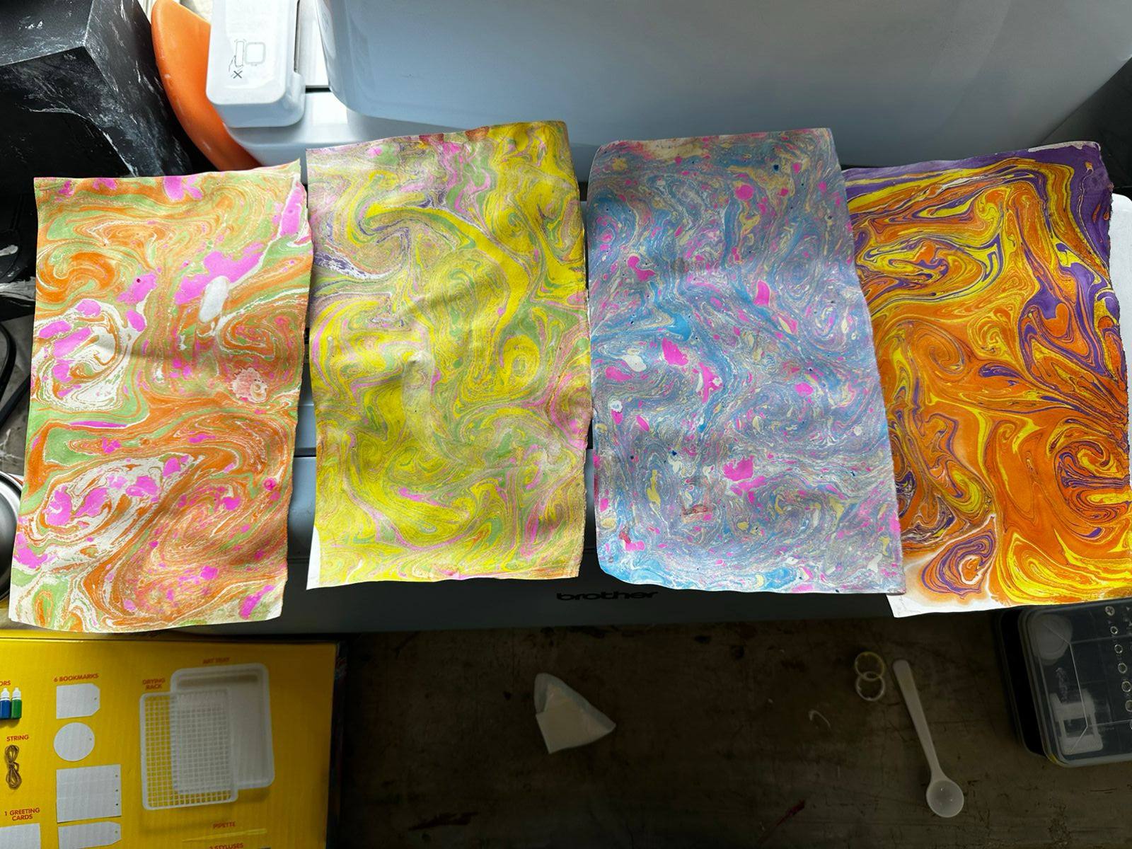
Visual Contrast Validation
Once the dosing parameters, head height and mixture viscosity were established, chromatic combination tests were performed. Three variants of triadic mixtures were developed in independent containers to evaluate the interaction of pigments. As can be seen in the images, this record allows identifying combinations with greater contrast and visual fidelity, validating the effectiveness of the drip system.