Week_10: Output Devices
 group assignment:
      • measure the power consumption of an output device
   individual assignment:
      • add an output device to a microcontroller board you've designed,
         and program it to do something
For the outputs setction I chose to focus on Motors and Displays since they would be most useful in my final project.
Servo Motor:
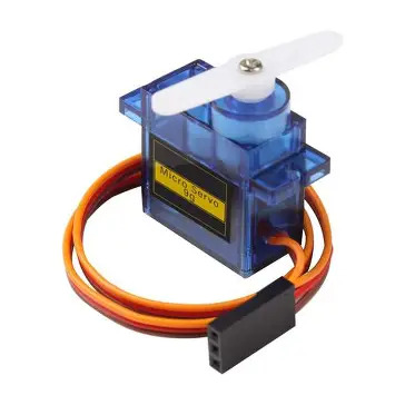
Servos are extremely useful and arecommonly used in electronics and robotics projects and I have no doubt I will need them so a good place to start is a 9g micro servo
Wiring:
since the wires for the servo are stuck together I am limited to one pin choice due to the pin out position of GND and 3v3 on the Xiao SEEED
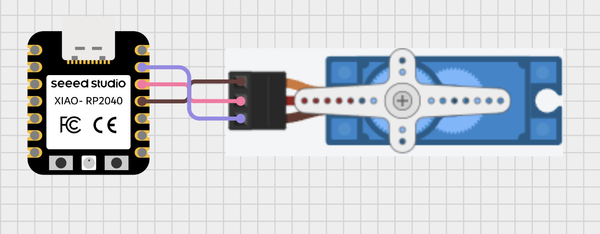
GND - GND
VCC - 3V3
SIG - D10
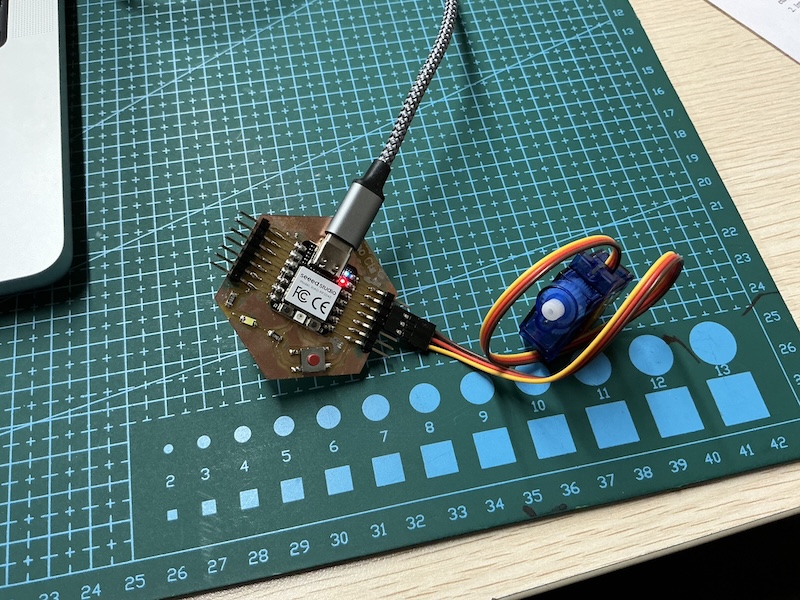
Assembled circuit
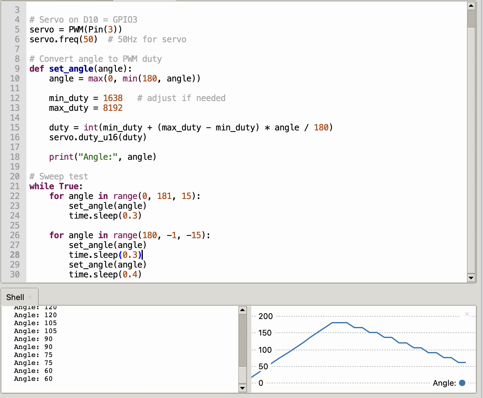
Programming:
For the code once again chat GPT was a big help but didn't give the correct pin connection as per my diagram because I didn't specify. Here is the original prompt:
“I have a 3 pin 9g micro servo how can I connect it to my Xiao Seeed rp2040 and program it using micro python to display the angle it is Turning”
I then told it to connect the signal pin to D10 and got the code below as a result:
Stepper motor:
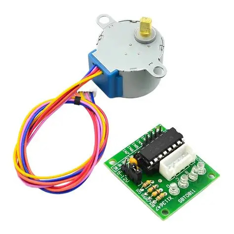
I plan on having a rotating drone arm in my final design using a stepper motor and a 28byj-48 is a great starting point and I will be using a standard breadboard power supply to power the driver board
Wiring guide
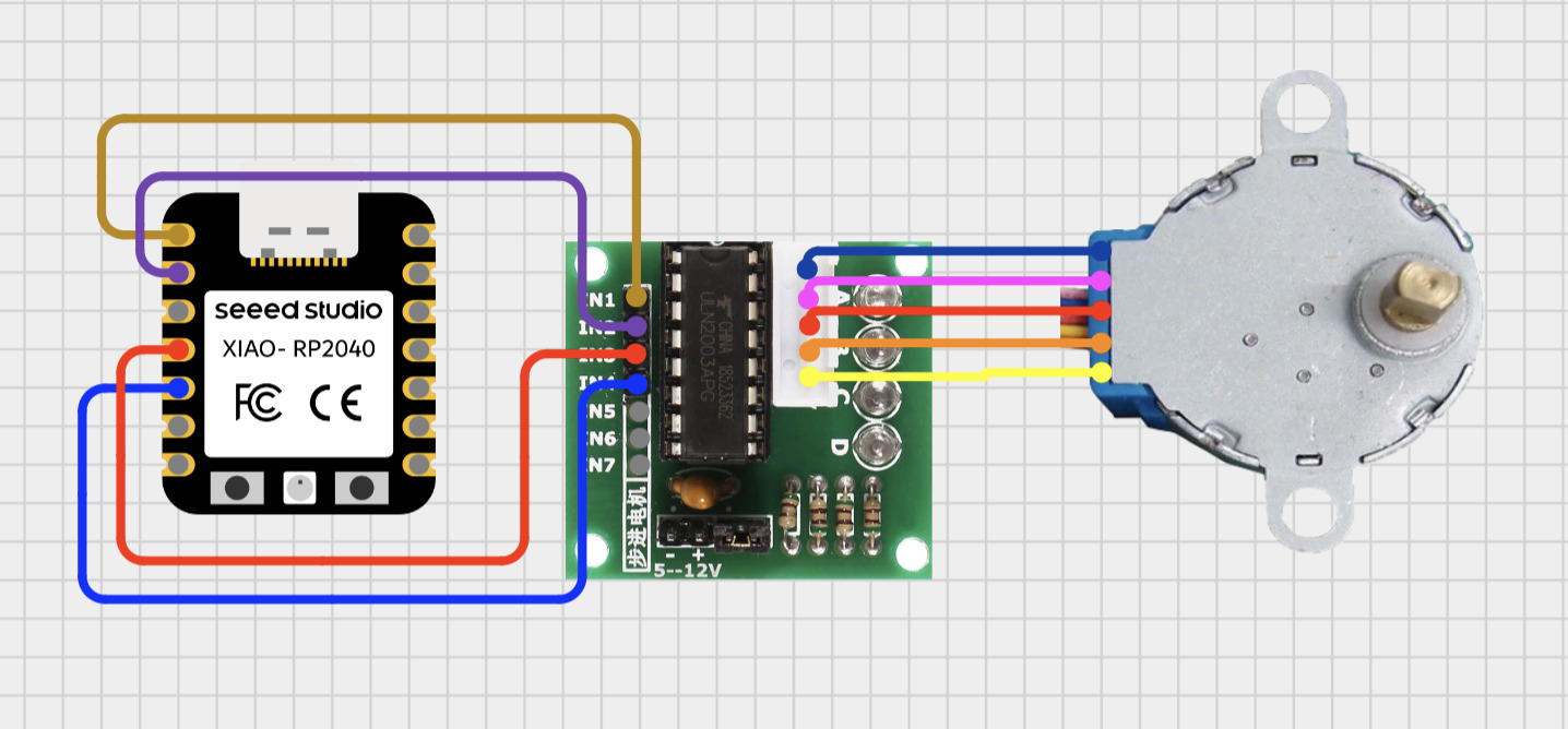
| ULN2003 Pin | XIAO Pin | GPIO |
|---|---|---|
| IN1 | D0 | GPIO26 |
| IN2 | D1 | GPIO27 |
| IN3 | D2 | GPIO28 |
| IN4 | D3 | GPIO29 |
| VCC | 5V | external |
| GND | GND | external |
completed circuit
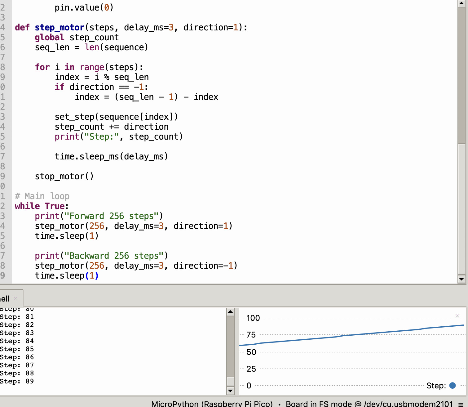
Programming
For the coding I used chat got here is the prompt:
I have a 28byj-48 stepper motor and driver board give me a wiring guide for the Xiao seeed rp2040 and code to make it run displaying the amount of steps in the shell for thonny using micropython
The wiring wasn't convented because of the button on G7 so I asked chat to change it
“can we change the wiring to start at D0” and it resulted in the code below:
OLED 1306 Module
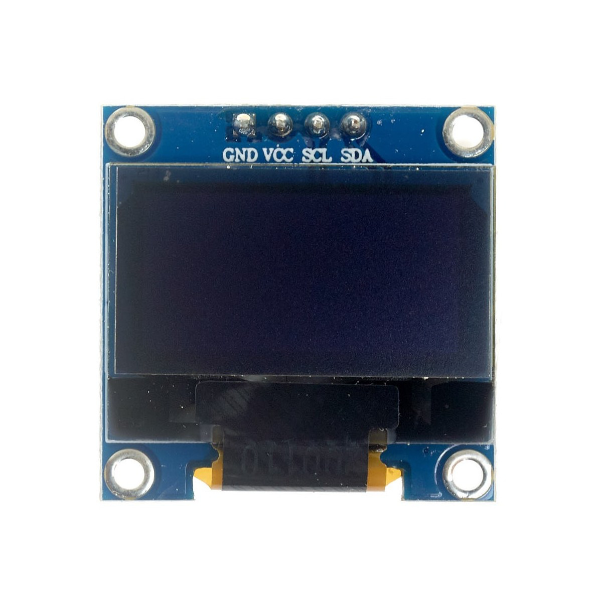
I would like to include a screen in my system to display relevant data such as battery charge levels and any other relevant system information and the OLED 1306 is a compact option that doesn't require a lot of pins
Wiring guide:
Here is the Circuit designer app wiring diagram
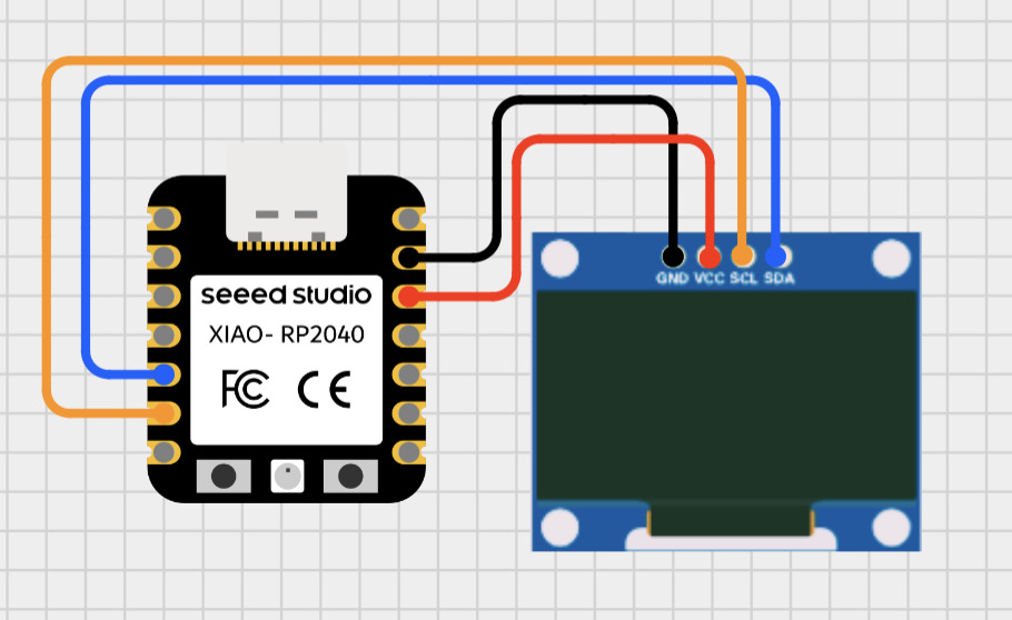
- GND → GND
- VCC → 3V3
- SCL → D5
- SDA → D4
Programming:
Once again I used Chat GPT. Prompt:
Give me wiring and MicroPython code for a XIAO RP2040 and SSD1306 OLED (I2C). Show simple geometric patterns and animations using basic drawing functions. Keep it simple and ready to run.
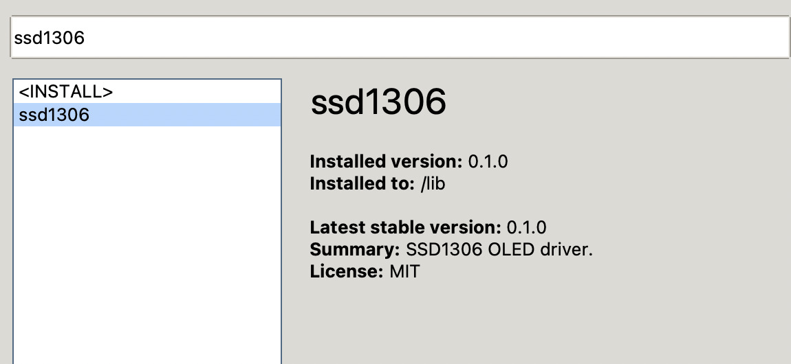
Click “tools” and search ssd1306 to install install the ssd1306.py module from the Thonny package manager
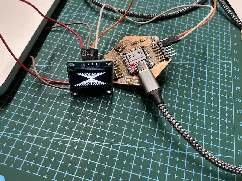
Final product:
IPS Screen module
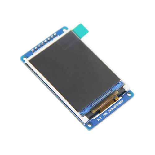
The OLED screen was a bit limiting in both size and color so I will test this 8 pin IPS screen module
Wiring Guide:
I couldn't find an exact replica on cirkitt designer app but found this 2.4” model with the same pinout so I used that instead.
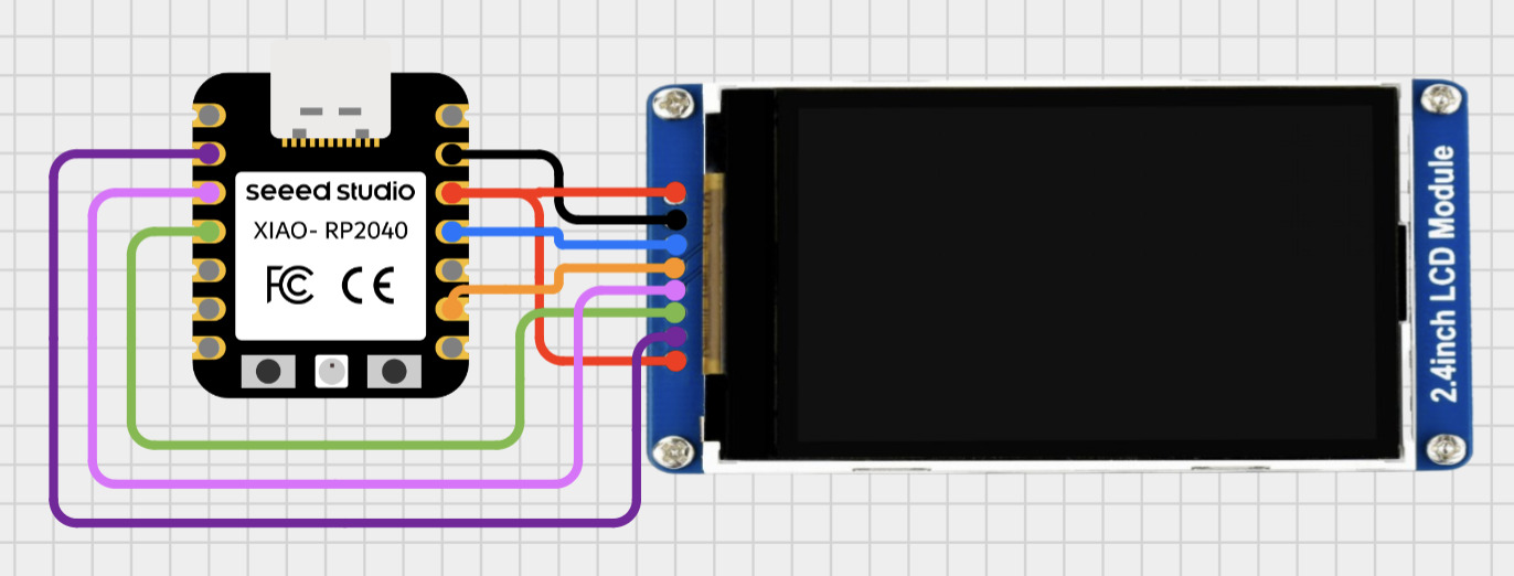
| LCD Pin | What it means | Xiao RP2040 Pin |
|---|---|---|
| VCC | Power | 3V3 |
| GND | Ground | GND |
| CLK | SPI Clock (=SCL) | D8 |
| DIN | SPI Data In (=SDA/MOSI) | D10 |
| RST | Reset | D1 |
| DC | Data/Command | D3 |
| CS | Chip Select | D2 |
| BL | Backlight | 3V3 |
Programming:
First I downloaded the driver as it was failing from the thonny package manager and uploaded it tho the Xiao. I tried Chat gpt but was unsuccessful and switched to Claude here is my prompt:
“Write MicroPython code for a Seeed Xiao RP2040 and a 2" ST7789V 240x320 IPS SPI display that cycles through 7 colorful geometric patterns every 5 seconds. Wiring: CLK→D8, DIN→D10, RST→D1, DC→D3, CS→D2, VCC+BL→3V3, GND→GND. Display is initialized with SPI(0), baudrate=40000000, polarity=1, phase=1, xstart=0, ystart=0. Driver is saved on device as st7789.py.
working example:
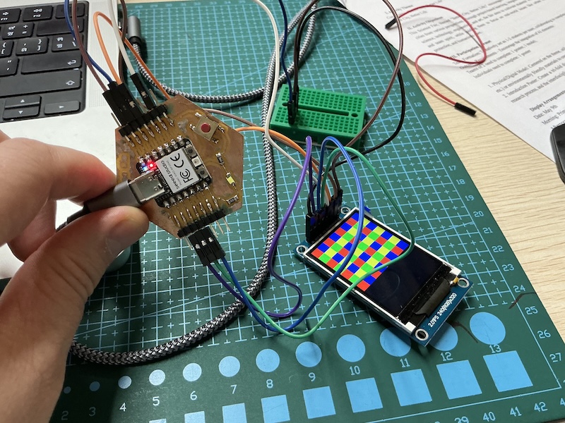
Code:
Driver: