Week_02:_Computer_Aided_Design
Assignments:
Model (raster, vector, 2D, 3D, render, animate, simulate, …) a possible final project, compress your images and videos, and post a description with your design files on your class page
Image and video compression:
Images and video will be essential to my documentation and due to the storage limitations on our git lab repositories finding effective means to compress images and videos is a must:
ImageMagick

For image compression and file type changes I will be using ImageMagick as it is fast and effective and can batch convert folders of images
ImageMagick cheat sheet
| Install ImageMagick | brew install imagemagick |
|---|---|
| Check installation | magick -version |
| Alternative check (older versions) | convert -version |
| Quick test (generate sample image) | magick logo: logo.png |
| Convert PNG → JPG (batch) | magick mogrify -format jpg *.png |
| Convert JPG → PNG (batch) | magick mogrify -format png *.jpg |
| Resize all images (50%) | magick mogrify -resize 50% *.jpg |
| Resize (max 1920px, no upscaling) | magick mogrify -resize 1920x1920\> *.jpg |
| Compress JPG quality | magick mogrify -quality 75 *.jpg |
| Resize + compress | magick mogrify -resize 1600x1600\> -quality 80 *.jpg |
| Strip metadata | magick mogrify -strip *.jpg |
| Resize + strip + compress | magick mogrify -resize 1600x1600\> -strip -quality 80 *.jpg |
| Convert PNG → compressed JPG | magick mogrify -format jpg -quality 75 *.png |
| Convert to WebP (efficient web format) | magick mogrify -format webp *.jpg |
FFmpeg

FFmpeg is a powerful, open-source command-line tool used for working with video and audio files. It seems to function similarly to ImageMagick so it could be the Ideal video editor for my current workflow
as we can see just converting files to mp4 can have great results on file compression
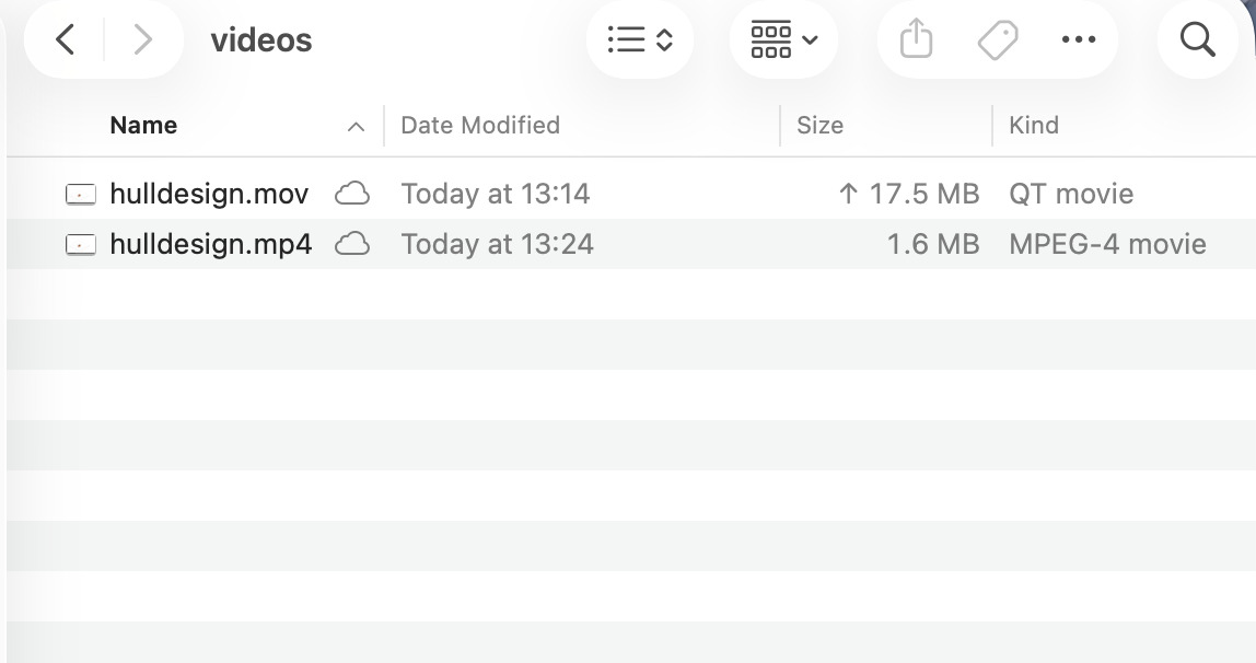
- Here is a video of me modeling one hull for my final project converted to mp4 using ffmpeg
FFmpeg Cheat sheet
| Install FFmpeg | brew install ffmpeg |
|---|---|
| Check installation | ffmpeg -version |
| Convert video format | ffmpeg -i input.mov output.mp4 |
| Compress video (standard) | ffmpeg -i input.mp4 -c:v libx264 -crf 23 output.mp4 |
| High compression (smaller file) | ffmpeg -i input.mp4 -c:v libx264 -crf 28 output.mp4 |
| Better quality (larger file) | ffmpeg -i input.mp4 -c:v libx264 -crf 18 output.mp4 |
| Resize video (720p) | ffmpeg -i input.mp4 -vf scale=1280:720 output.mp4 |
| Remove audio | ffmpeg -i input.mp4 -an output.mp4 |
| Extract audio | ffmpeg -i input.mp4 audio.mp3 |
2D Design
I would like to explore incorporating my iPad into my workflow for design work and I think it could be an Ideal drawing and sketching tool with the pencil tool. So I will compare some free iPad sketching apps to their effectiveness and user friendliness for the task of improving my initial sketch
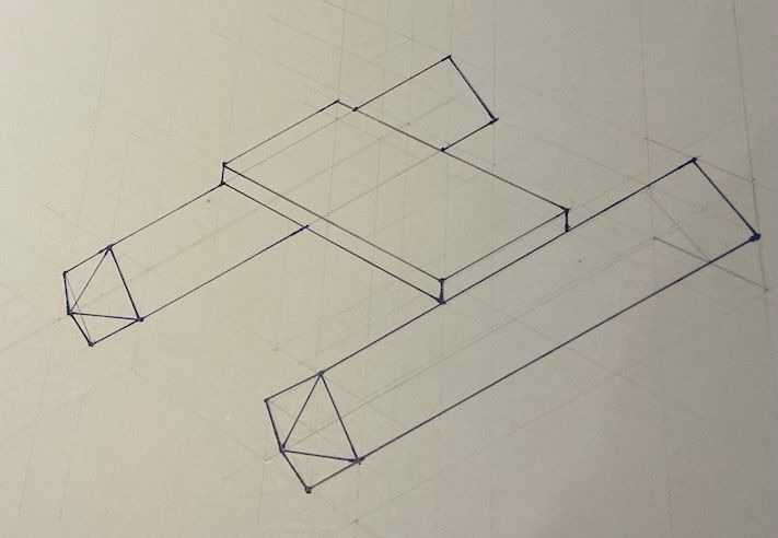
I want to also experiment with different types of polygons so I will sketch it with a pentagonal shape as I think this might create a superior hull shape for this flat top design
Drawing pad
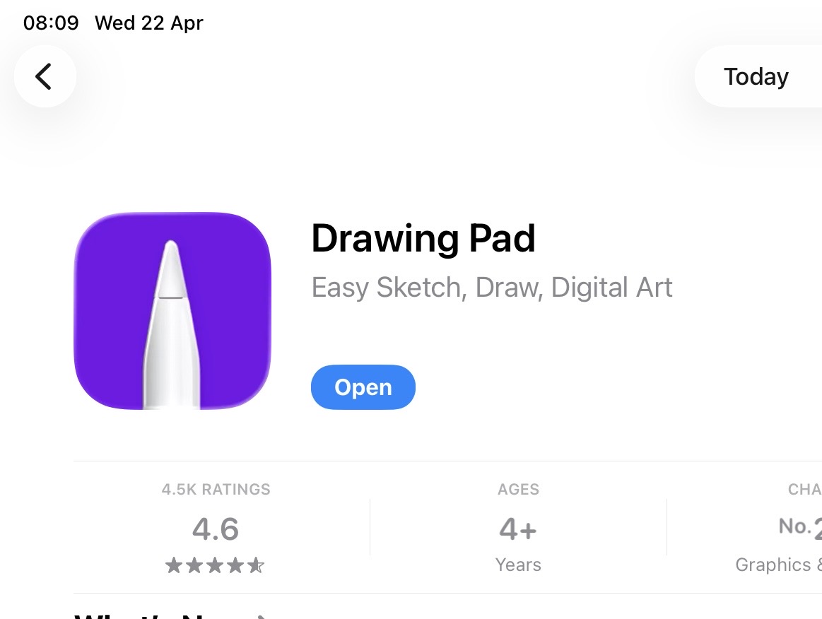
First I will be using a basic sketching app from the App Store called drawing pad as it had a free trial and a decent rating
I found it undeserving of its rating and extremely mediocre. The app is extremely slow and has a predatory payment model that kicks in after only two days with limited sketching tools and poor quality sketches and a dot pattern watermark on the image that you cannot get rid of.
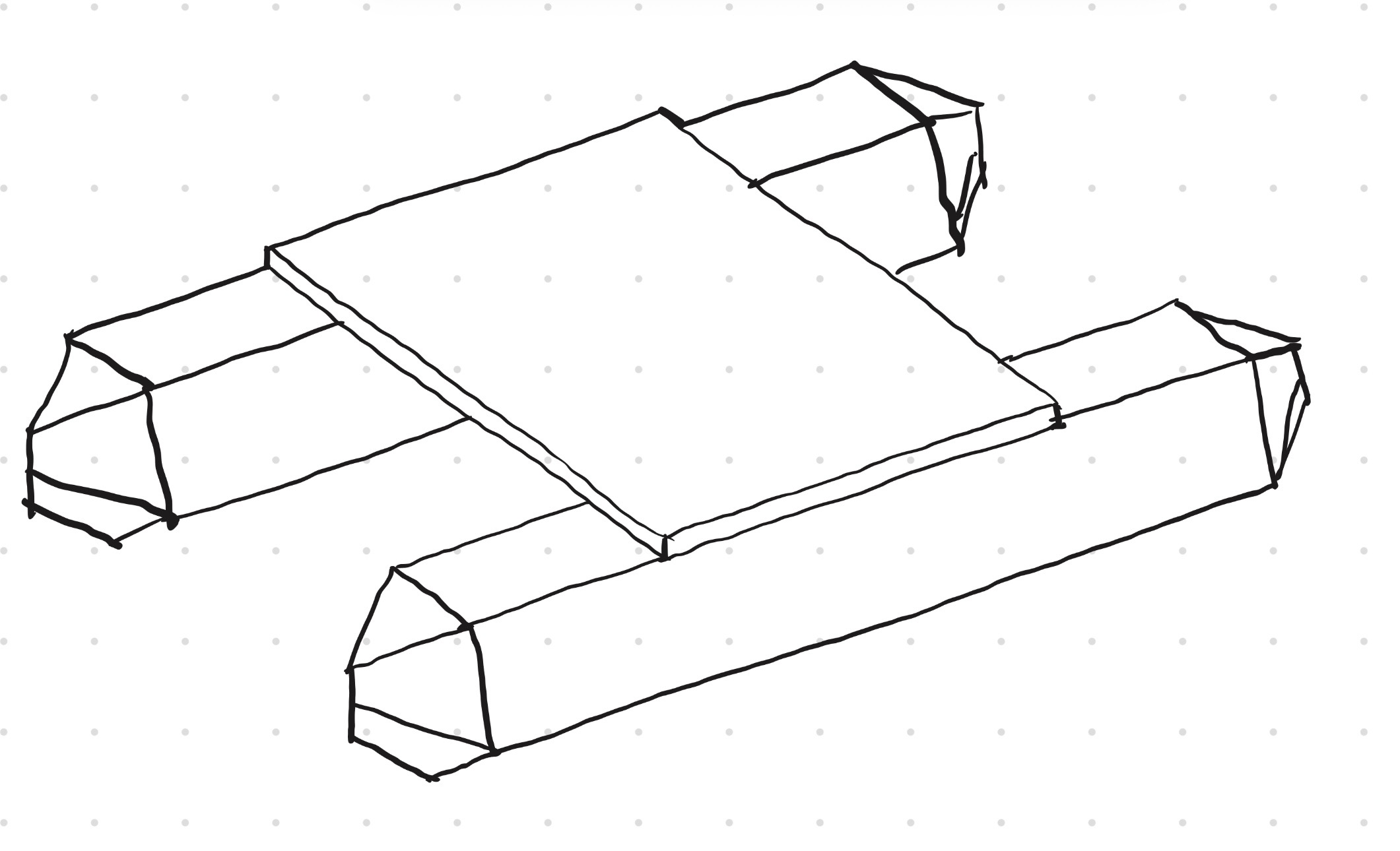
However this was definitely an improvement on my original sketch and took a lot less time and equipment so I think incorporating the iPad into my sketching workflow could easily improve my efficiency
converting to 3D:
even through the app is terrible I do want to convert the sketch to 3D because it is an improvement on the original design and for this I will be using my standard fusion 360.
I began by making a hexagon and drawing construction guide lines. I then took the middle section and moved it up to create the wave piercing point of the bow. I then made a rectangle that was slightly longer and filleted the corners to make it round, positioning is just under the leading line that would form the point of the bow
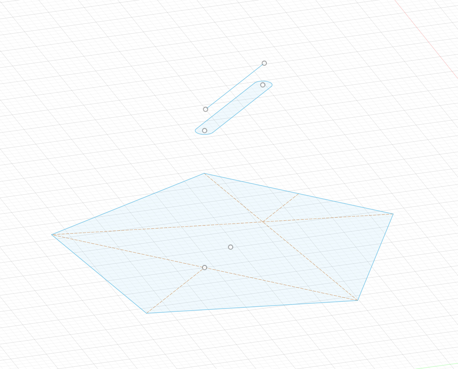
I then attempted to loft the 3 sketches together but could not connect the line in the front.
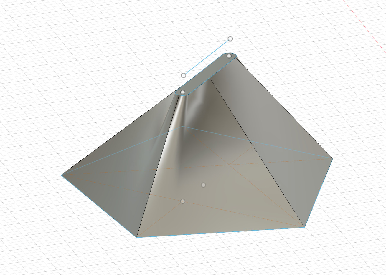
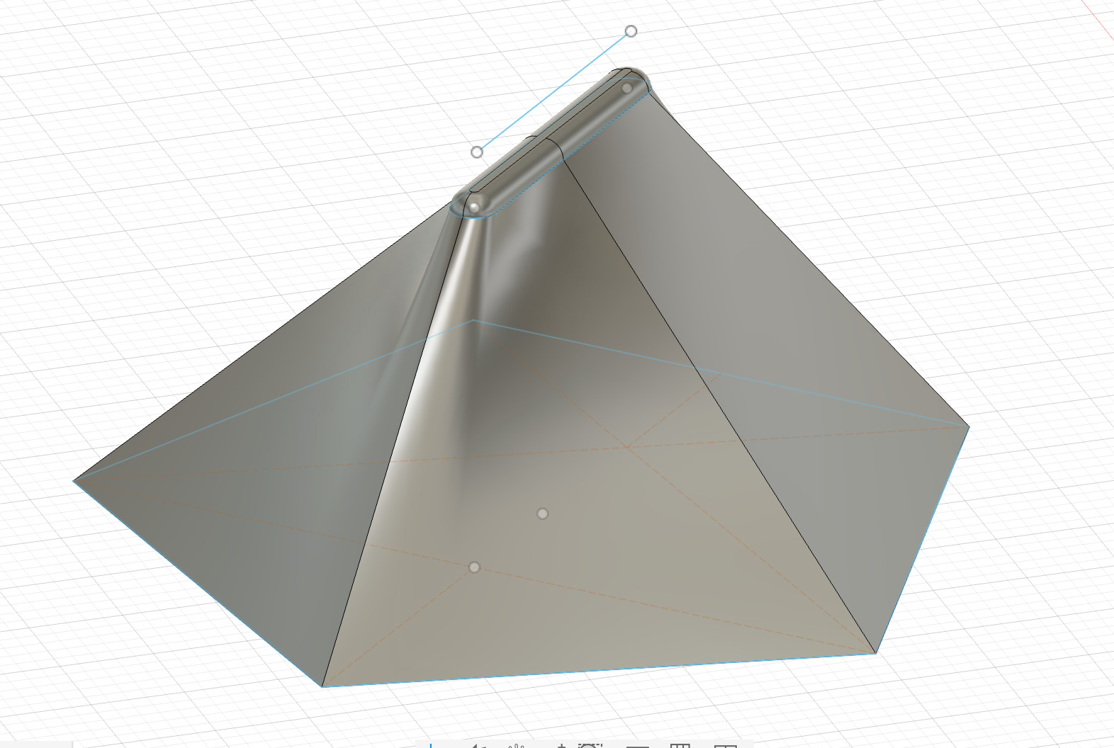
So I simply extruded the front and used the fillet function it to create a more hydrodynamic shape
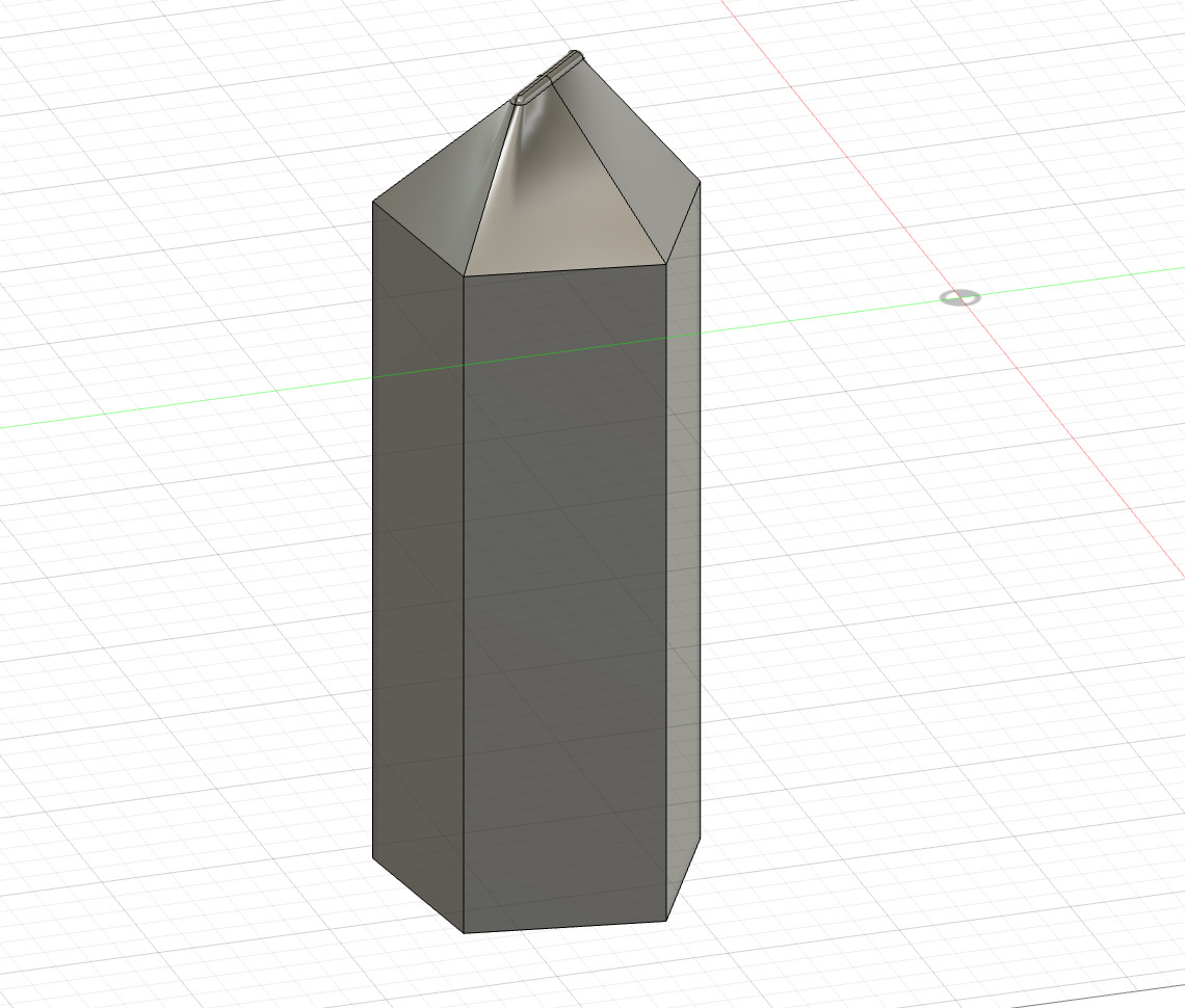
I then extruded the hexagon by half the total intended length
next I used the mirror function to duplicate the hull shape for the rear section
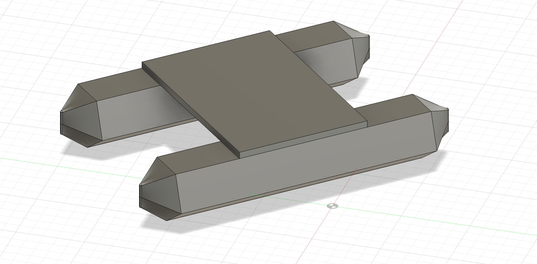
next we duplicate the hull to create a catamaran
create a sketch on the top surface of the hull
and finally extrude the solar panel
Sketchbook app
Sketchbook
Deeply unsatisfied with the previous app I tried Sketchbook and was pleasantly surprised.
No long loading times and a simple but effective UI with different brush types, functions and layers easily accessible
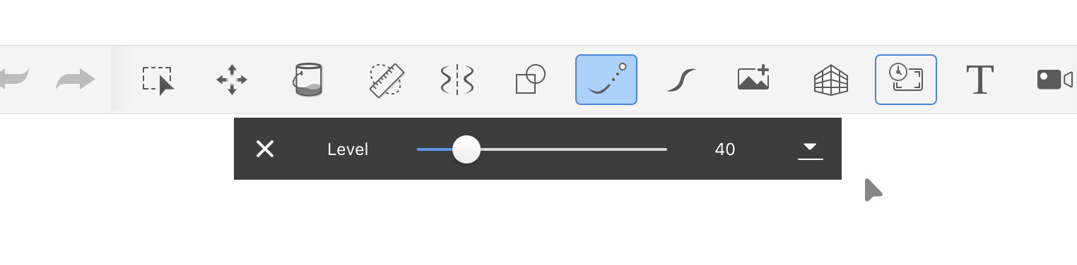
Steady stroke function:
This greatly improves the quality of your sketch as I find the lines I draw always to be shaky son this function smoothes out your lines for a much better final product
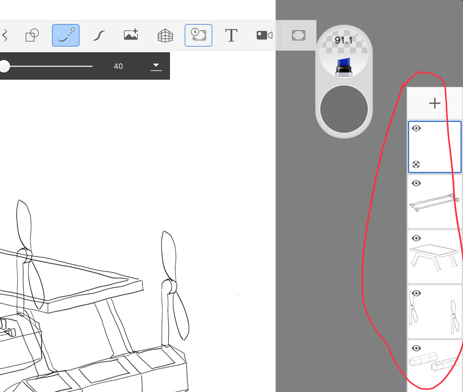
layers:
This will allow me to sketch and edit different elements and parts of my final design individually
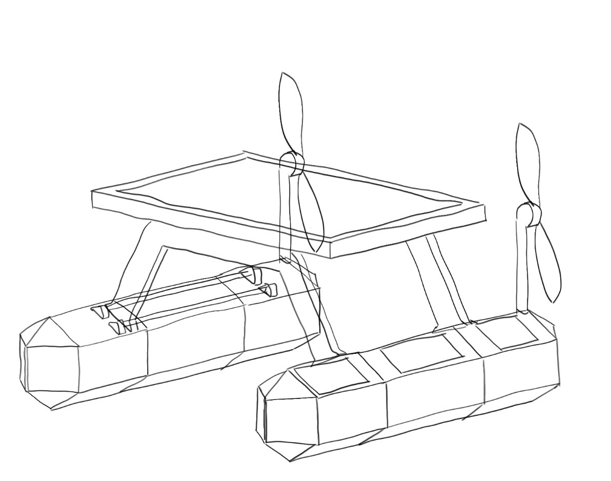
Improving on the previous iteration I wanted to:
- increase the freeboard of the solar panel platform
- add windows to allow access to components housed in the hulls
- add propulsion mechanism
- have modular connected hulls
- include a connecting mechanism
Final project sketch:
3D modeling the final hull design:
For the final project section of this week’s assignment I will be modeling the modular hull sections of the USV in fusion 360
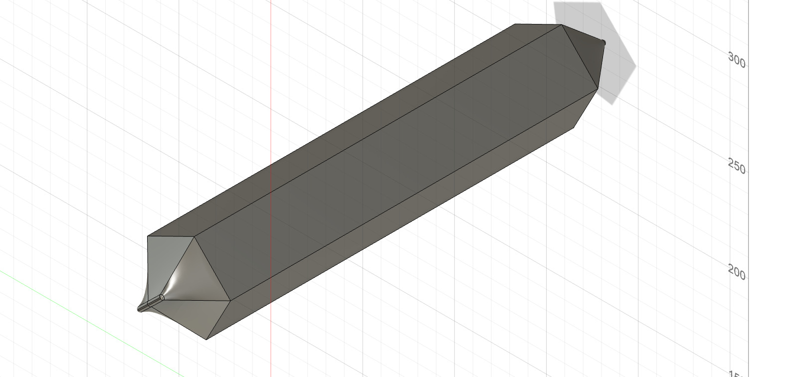
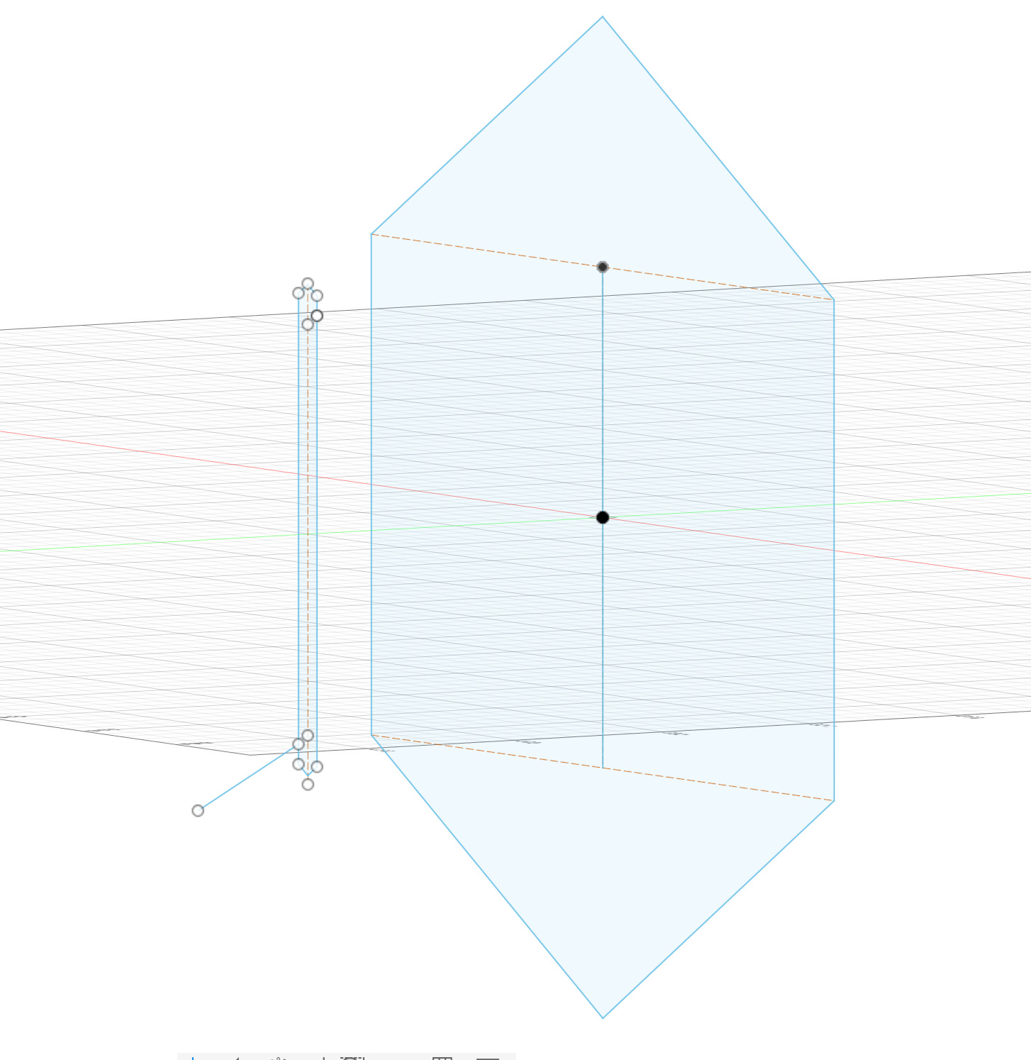
I began with a sketch by making a hexagon with a width of 25cm then I drew some construction line cross sections an a mid line to create the sketch of the bow point and moved it forward so that would be used to loft the two sections together
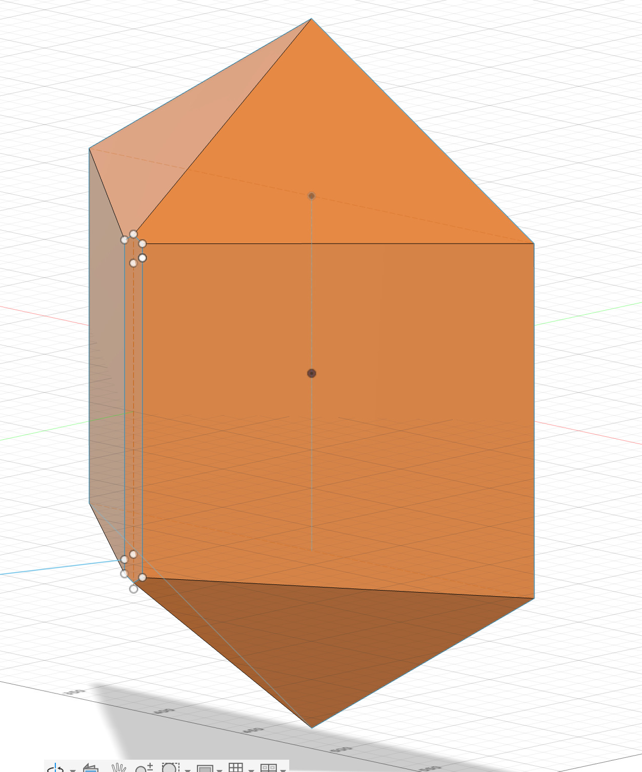
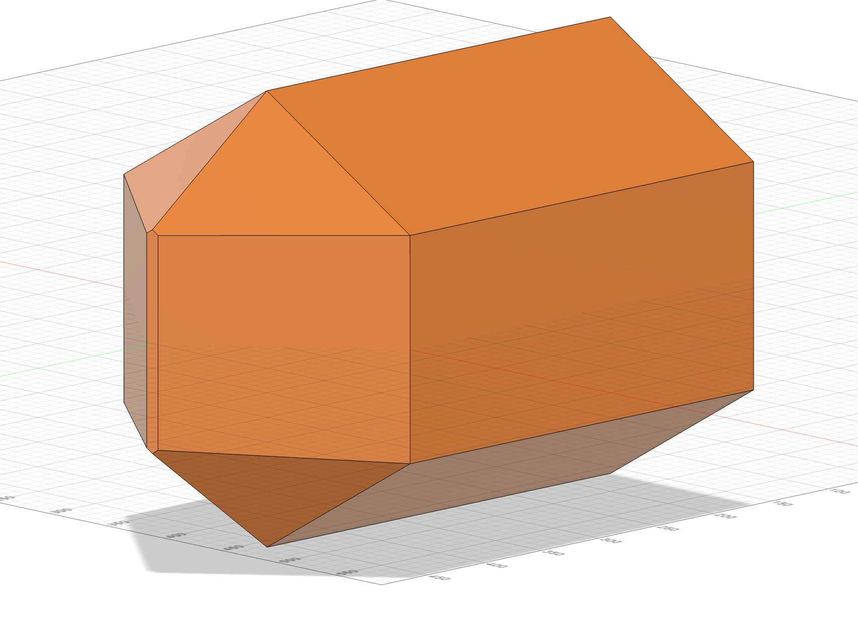
I then lofted the two sections together and extruded the back by 30cm to Crete the desired shape for the front section
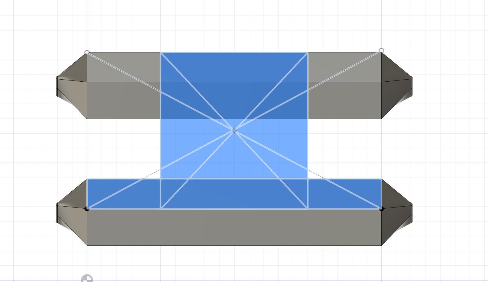
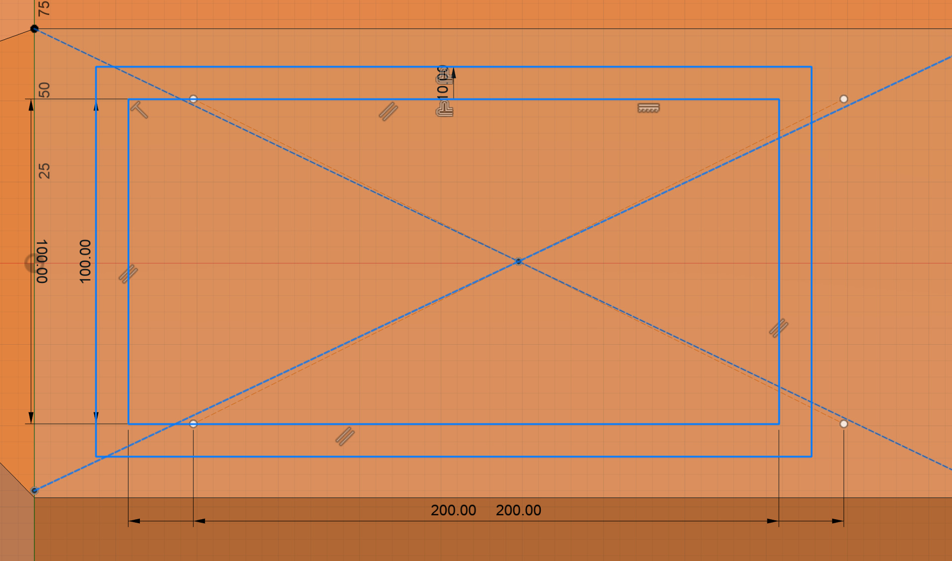
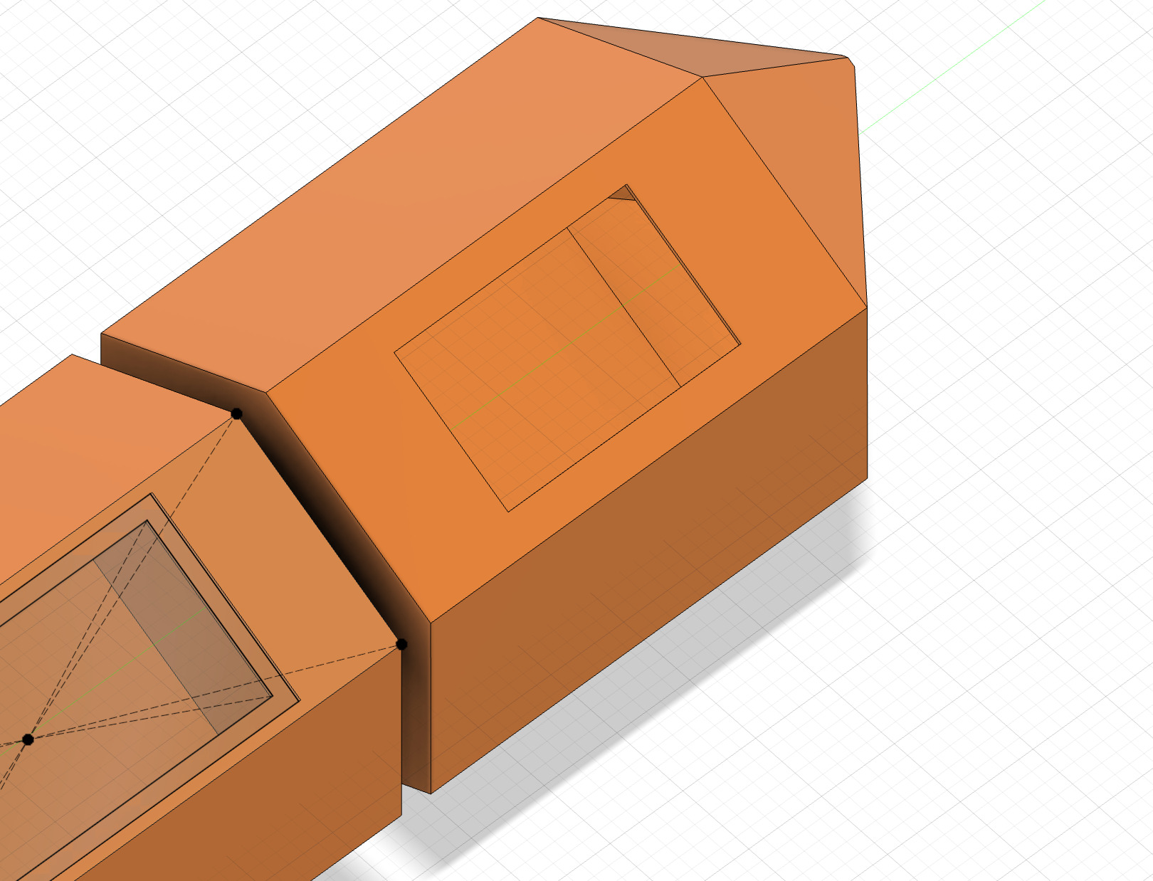
I then started on the port holes by creating a sketch on the outward facing to section of the hull. I drew construction lines from each corner in order to find the middle point of the panel and used that point to draw a rectangle from centre that lined up perfectly I then moved it forward to provide space for a hull module connecting mechanism
Next we make the extrusion hollow with the shell command using 2mm as I think that will provide adequate strength core for the fiberglass and cut the port hole by negative extrusion
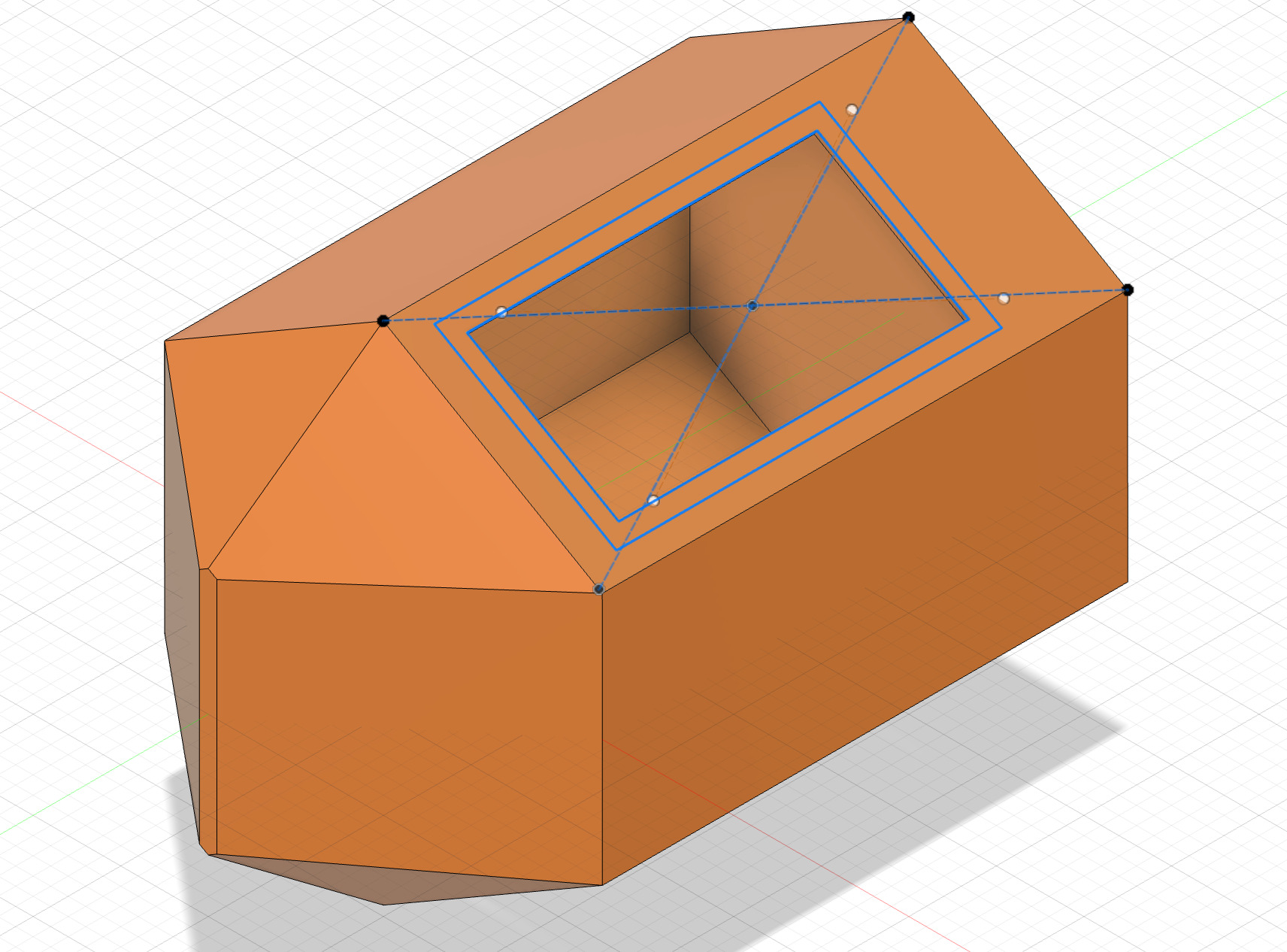
then I offset the rectangle to make an acrylic window that would cover the porthole and provide protection from water while still allowing visibility of the internal components
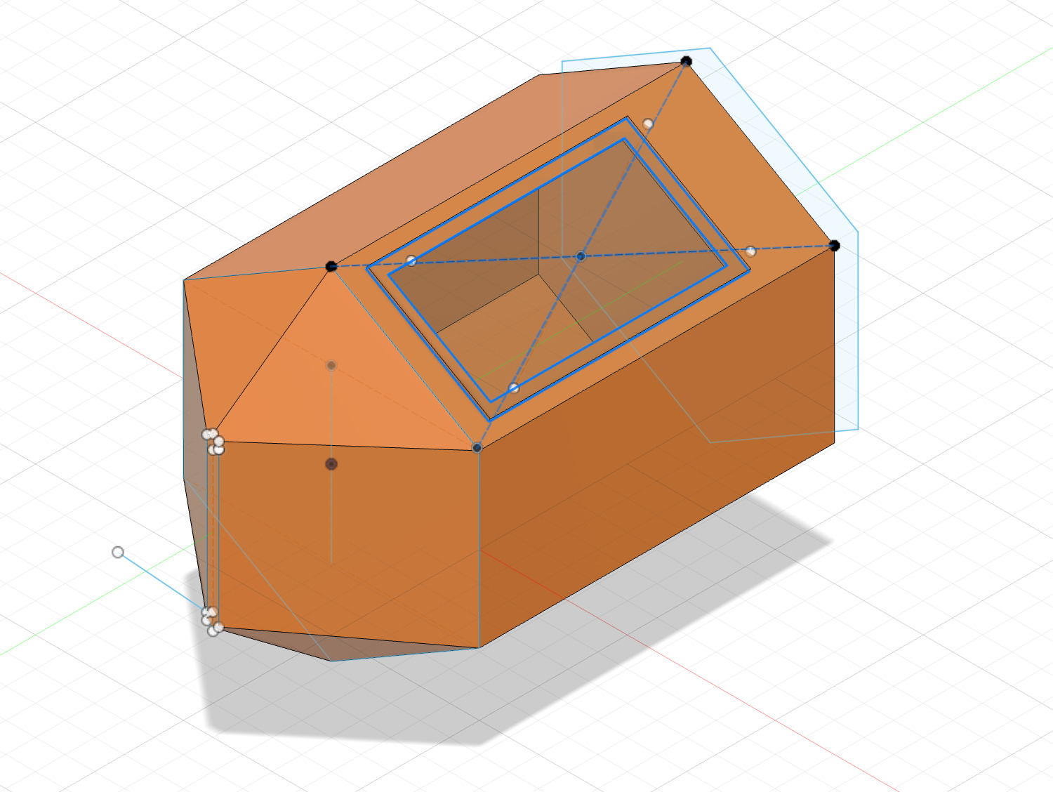
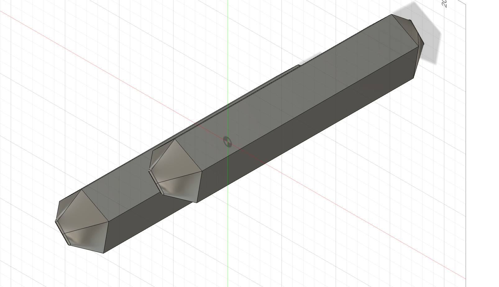
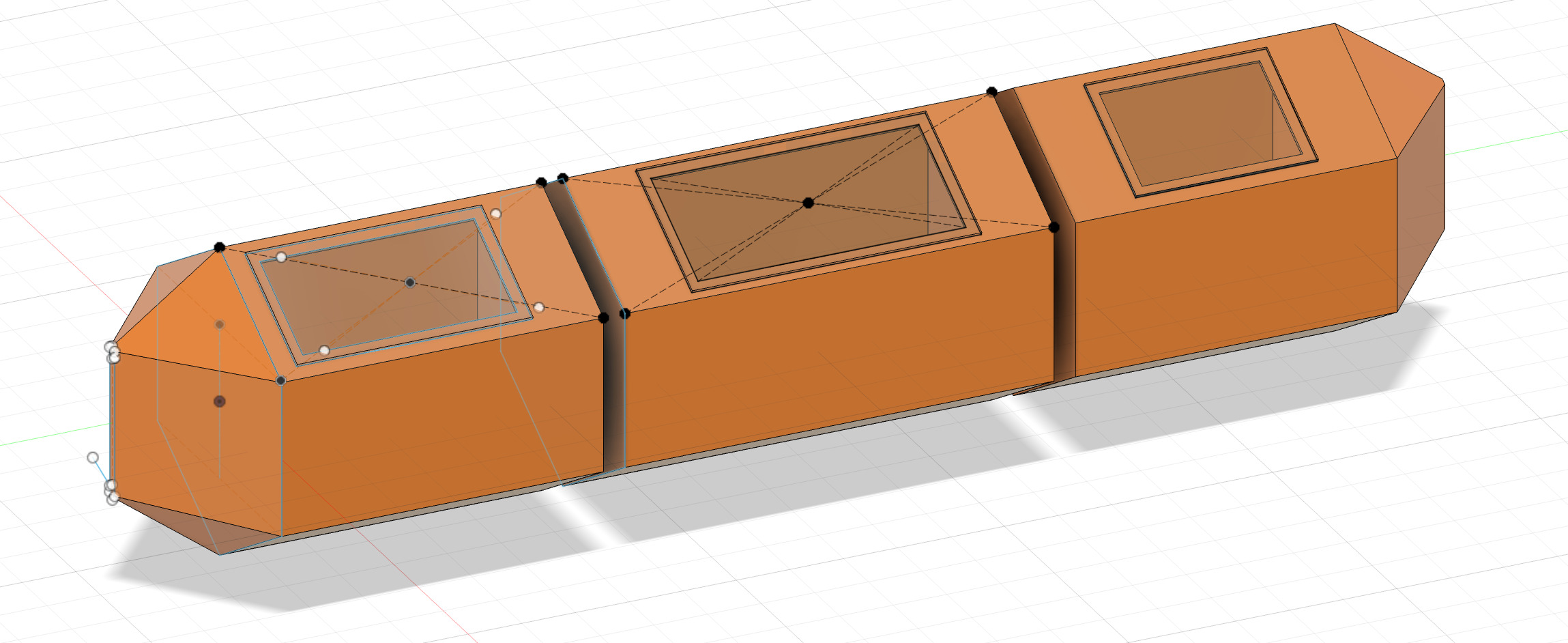
For the middle section I made a copy of the original hexagon and moved it back and repeated the extruding, shelling and window making from the first section but kept it central also making the window as large as possible as this is where the battery will be housed
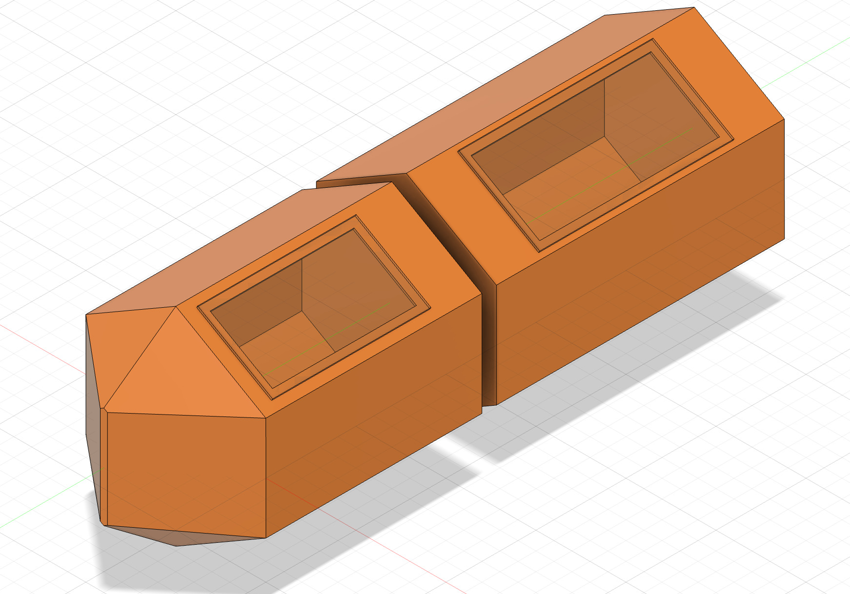
To create the back section I constructed a mid plane and mirrored the front hull module
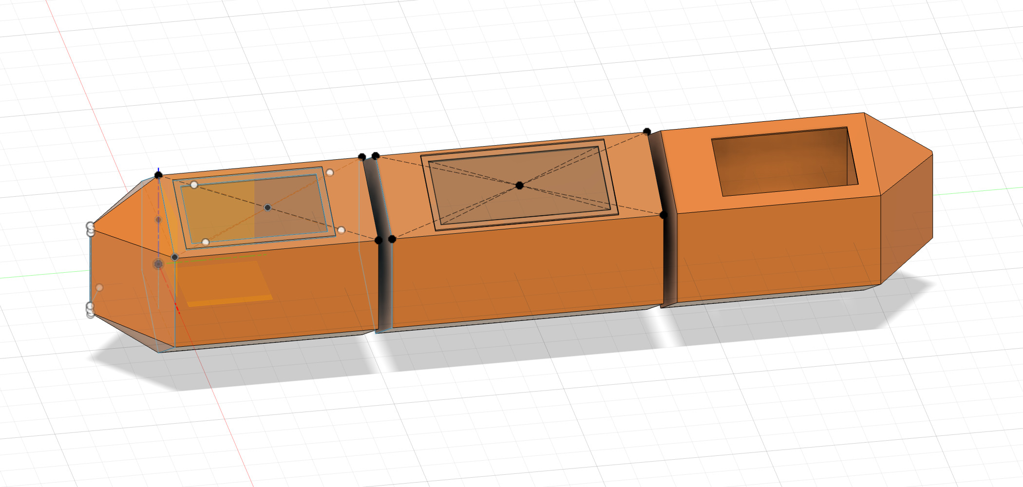
however I wanted the rear window section to be smaller than the from as I need to have room for the top mounted brushless motors so I simply selected the inner edge of the window and extruded it to the desired length
I then created the rear port hole using the same process as previous and the left hull section was complete
CAD software comparison
Brief:
Since I am familiar with using Fusion360 and my final project uses tetrahedrons as the basis of my design this will form the basis of my test. I will design my additive manufacturing assignment based on a tetrahedron in Fusion 360 and then I will go in blind on the other CAD softwares and see how difficult they are to figure out how to build a simple tetrahedron based on the fusion 360 work flow and If I fail I will use the internet to figure it out.
The CAD software I selected is:
- Solidworks xDesign
- Onshape
- FreeCAD
- Openscad
Fusion 360 (Control)
STEP 1:
Make a component and then create a sketch
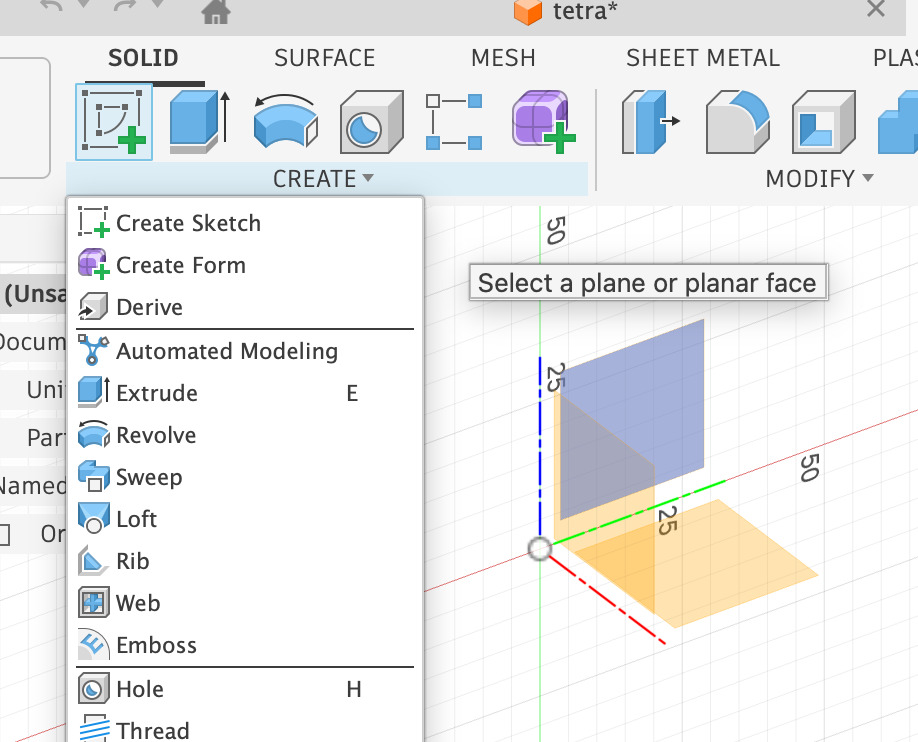
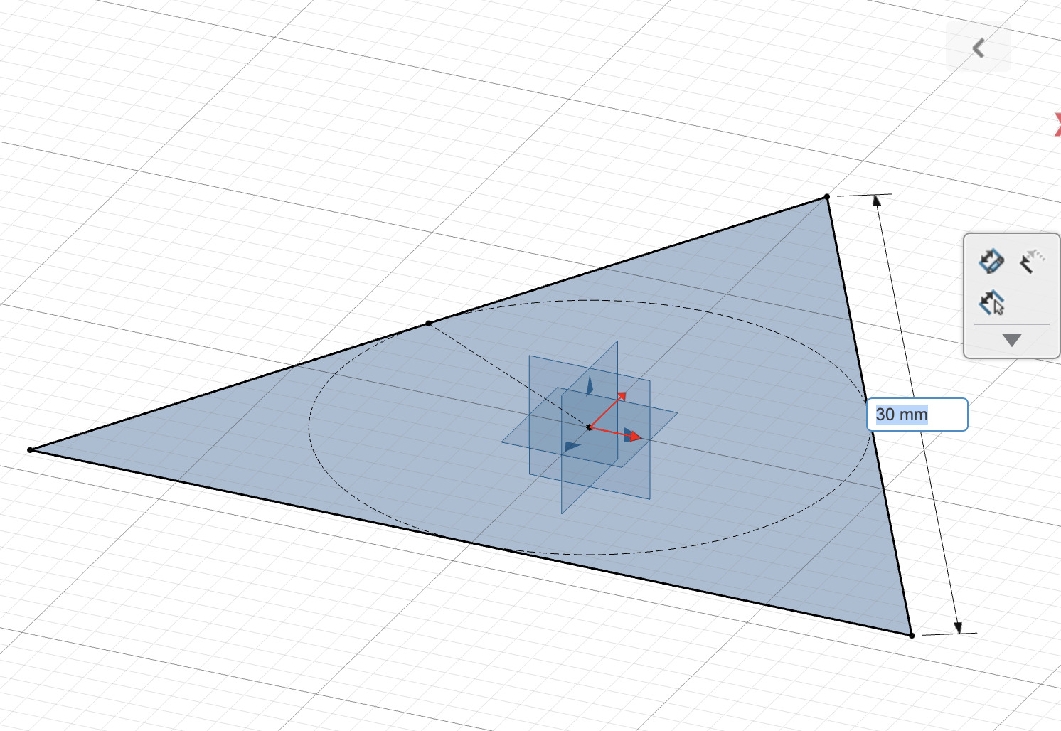
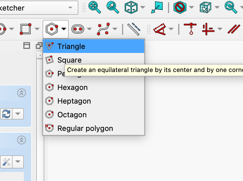
Choose your plane/origin that you would like to sketch on and select “polygon” under create. Click and drag to make you polygon and then press tab to change the number of sides to 3 which will make an equilateral triangle

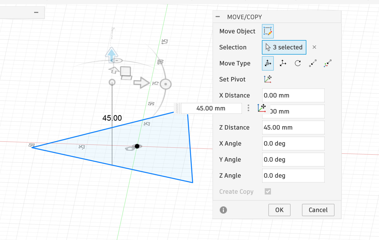
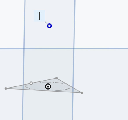
once you have the desired triangle right click and select move copy. This will open a menu and make sure you have “Create a copy” selected. Ensure you have selected both the triangle and the center point. Then move the copy up on the Z axis to the desired height. Now you should have two triangles on top of each other
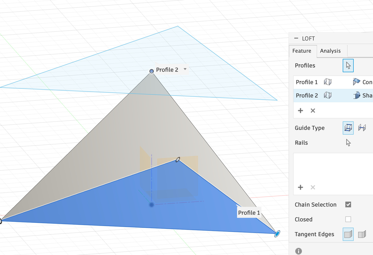
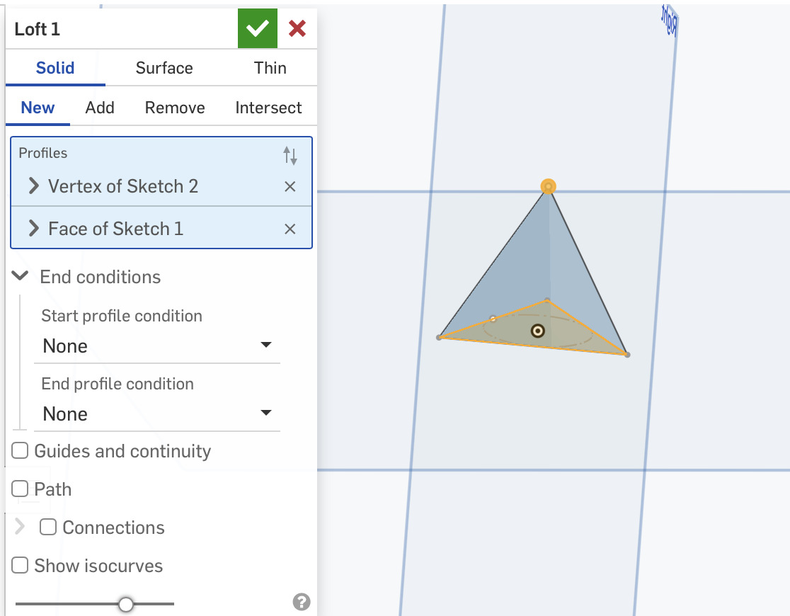
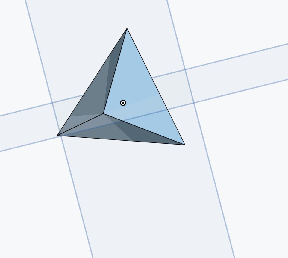
Under create select the Loft function and select the outline of the bottom triangle and the center point of the above triangle
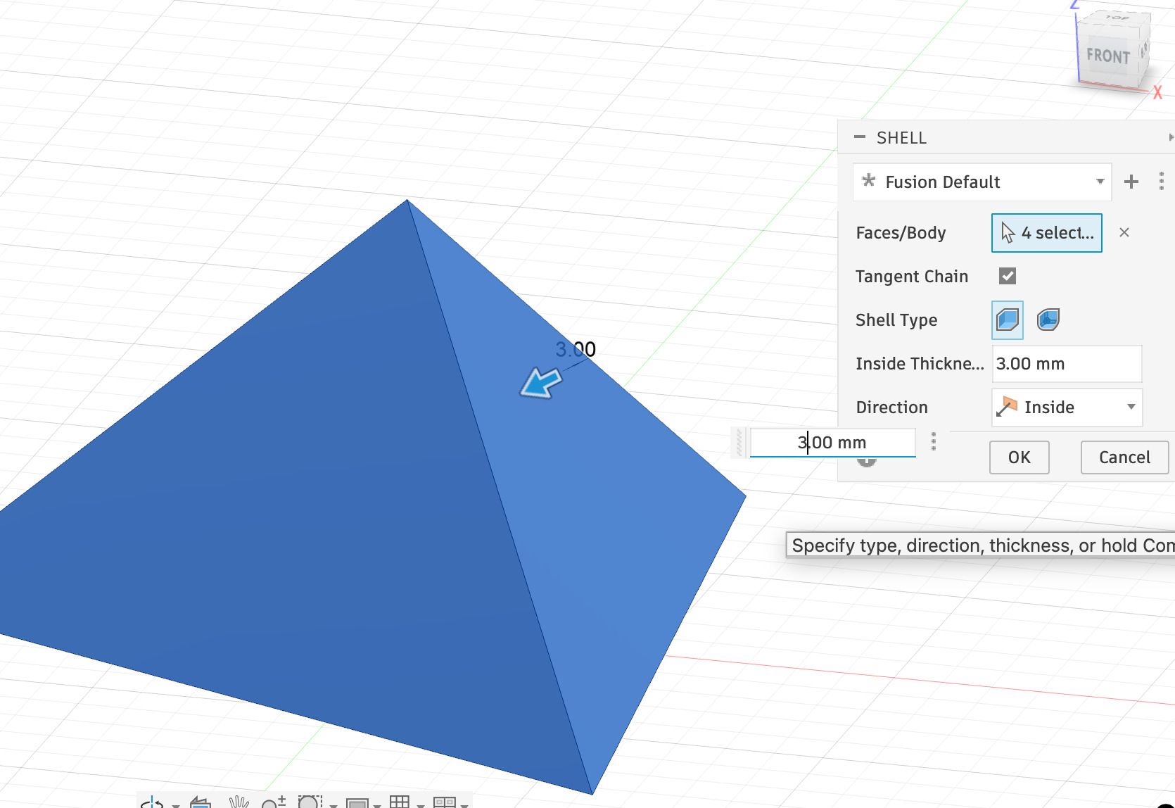
To make it hollow select the shell function and either Type or adjust the slider to select the desired wall thickness
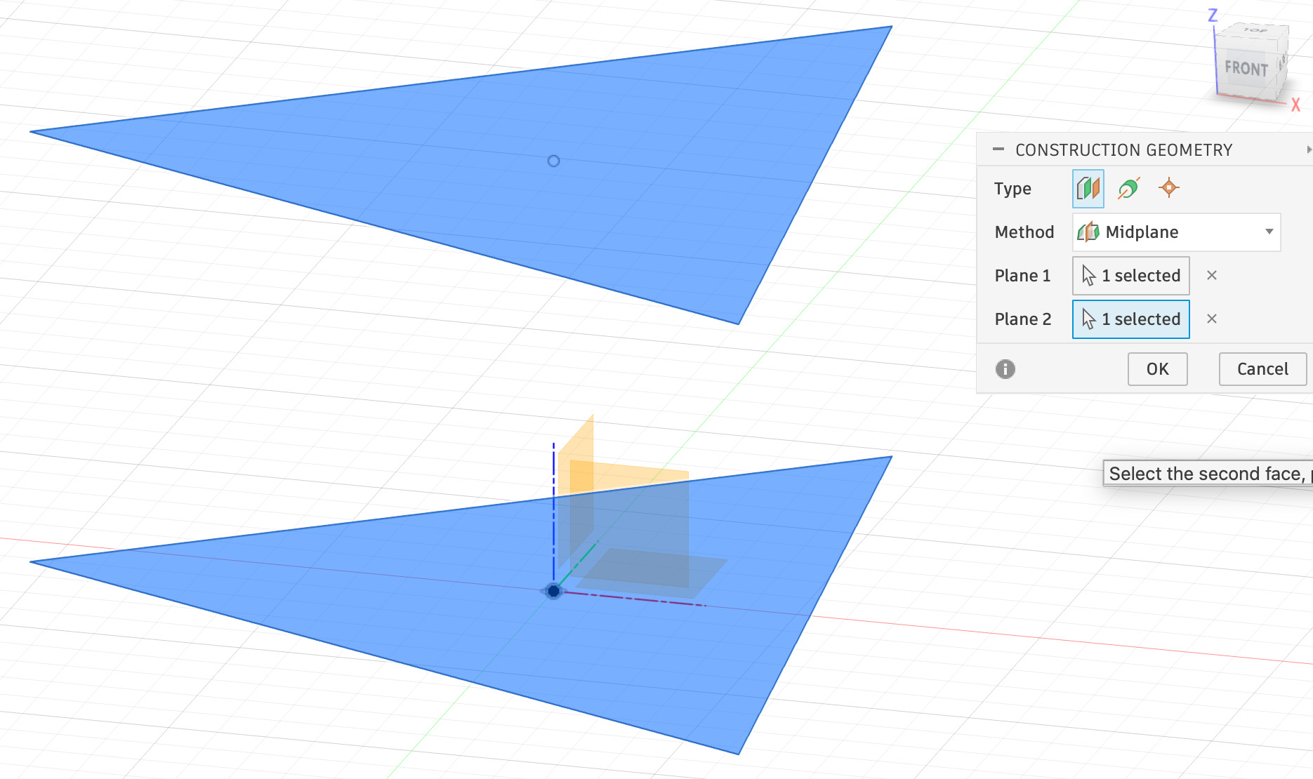
Then Under construct select mid plane and select the two triangle sketches (you can make this easier by hiding the bodies on the left menu. Once this is done use his mid-lane to plot the bodies then hide the top one.
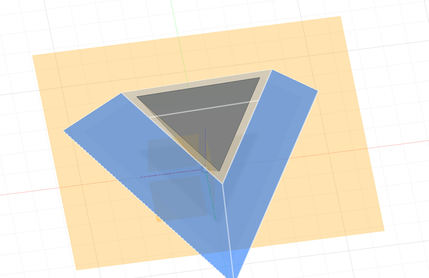
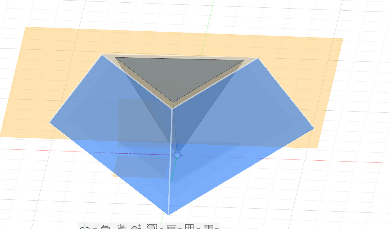
You can then use your loft tool to loft the inner triangle you made by splitting the hollow body with the center of the original bottom triangle which you can then shell to make hollow as well. And there you go a Tetrahedron inside a tetrahedron. Unhide the top section and hey presto!
SolidWorks xDesign
Overview:
- Navigation: The online experience is confusing. The navigation cube is lame as you can't easily use it to select isometric views or rotate.
- Sketching: Sketching base geometry is simple and intuitive.
- Lofting: Lofting especially the way I do to make tetrahedrons in Fusion is too difficult. cannot move sketches in planes they werent drown on and it refuses to loft to a point on a different palne
- Drafting: Drafting was the solution but like I said not intuitive and slow on web browser
- History: non existant.
Workflow:
I tried lofting in the way that I did in Fusion and failed. it refused to loft to the point I created so I had to find a new method
Make A sketch: Sketching is easy and intuitive for the polygon especially when it comes to adjusting the sides.
Extruding: Very simple just drag the up arrow and done.
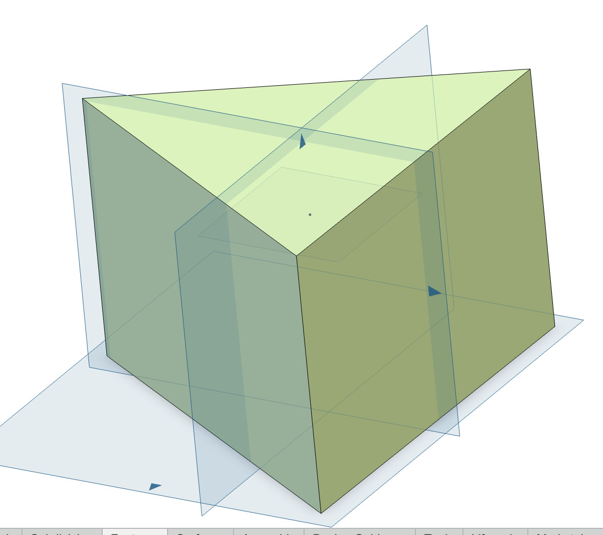
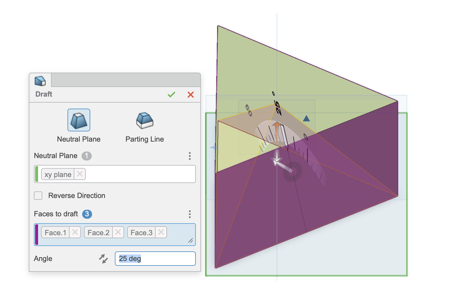
Drafting: kind of like the fillet function in fusion select the faces you want to “draft” then select the plane you want to stay the same and adjust the slider as needed.
Finished product: Easy one you know the correct workflow
Verdict: Yuck!
Onshape
Style & Experience Notes:
- UI: User interface is simple and uncluttered
- Dimensions: Adjusting dimensions was trickier than the others.
- Speed: Overall the easiest and fastest program.
Workflow:
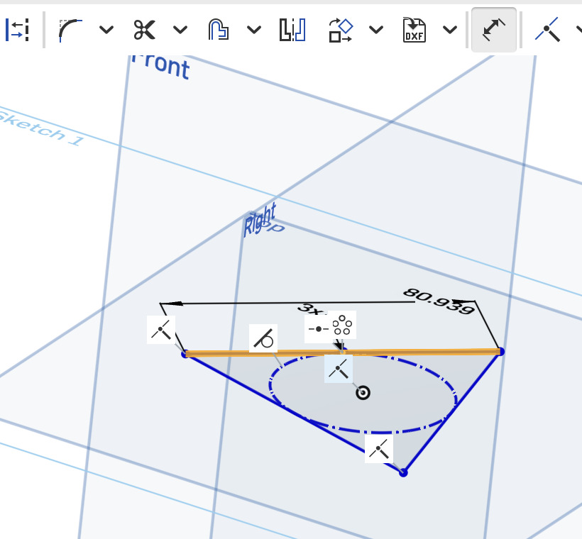
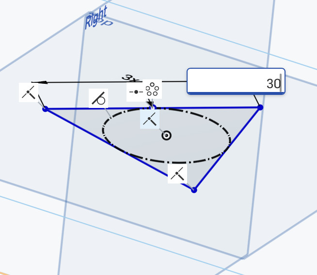
Base: Sketch an inscribed polygon, adjust the sides to 3 by moving your mouse. Adjust the side length by clicking the dimension button then clicking one of the sides and dragging it so the dimension parameter pops up.

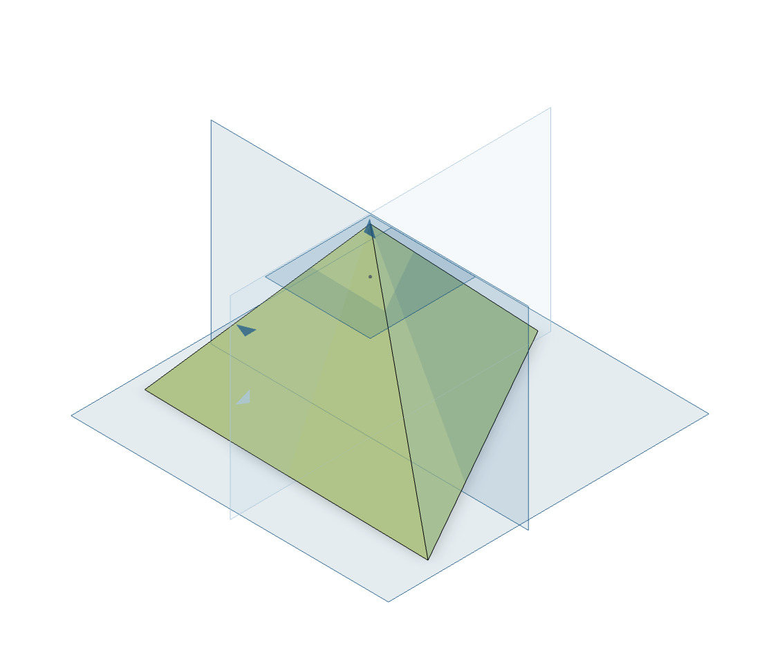
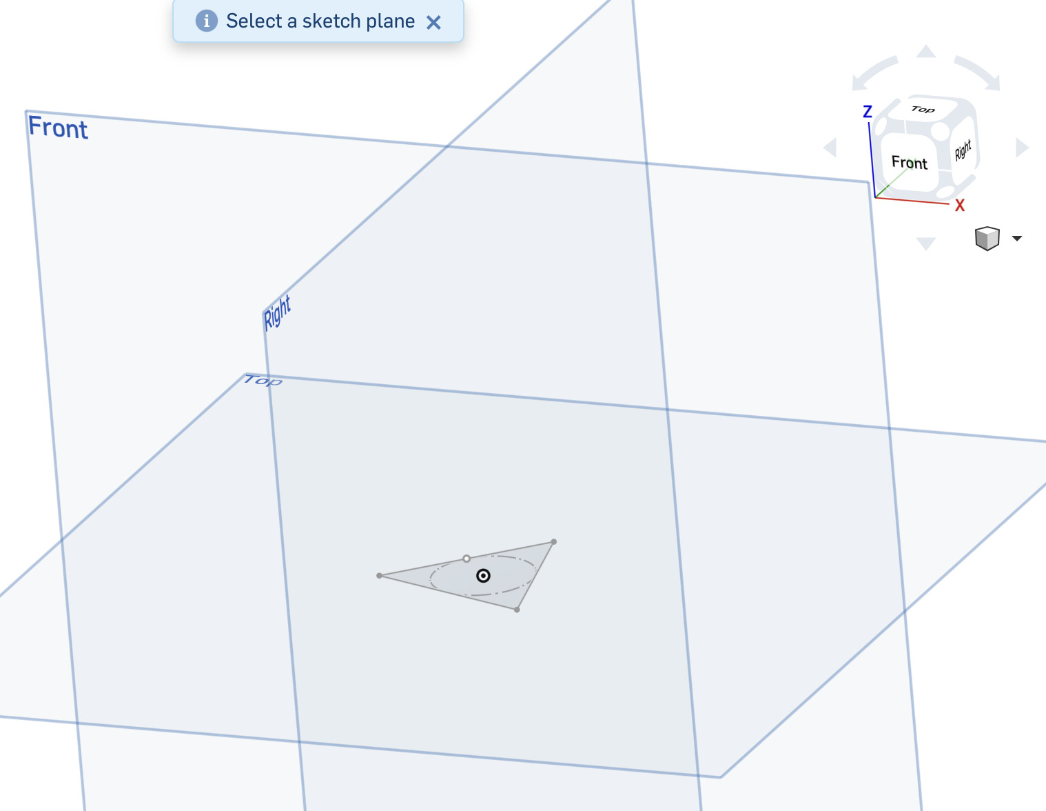
Apex: Create a sketch on the Front or Right plane and place a single point at the desired height above the base.
Loft: Use the Loft tool to connect the triangle to the point.
Verdict: Pretty good!
FreeCAD
Overview:
- Comparison: Only program that can SKETCH A TRIANGLE without adjusting a polygon.
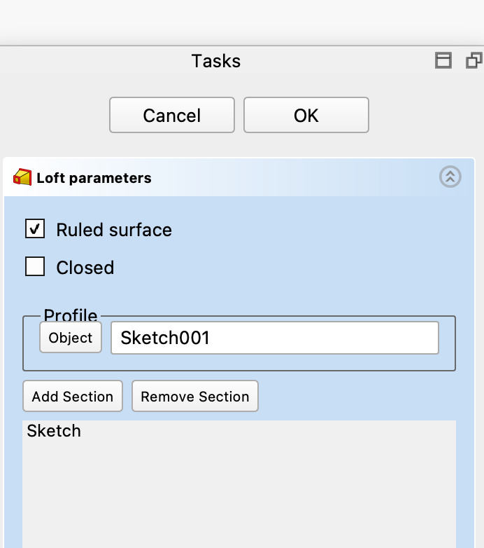
- Lofting: A bit tricky You must click "Add Section" before selecting the next sketch for a loft to work. and its hard to find the point.
- Add ons: Optional polygon add on if you want.
Workflow:
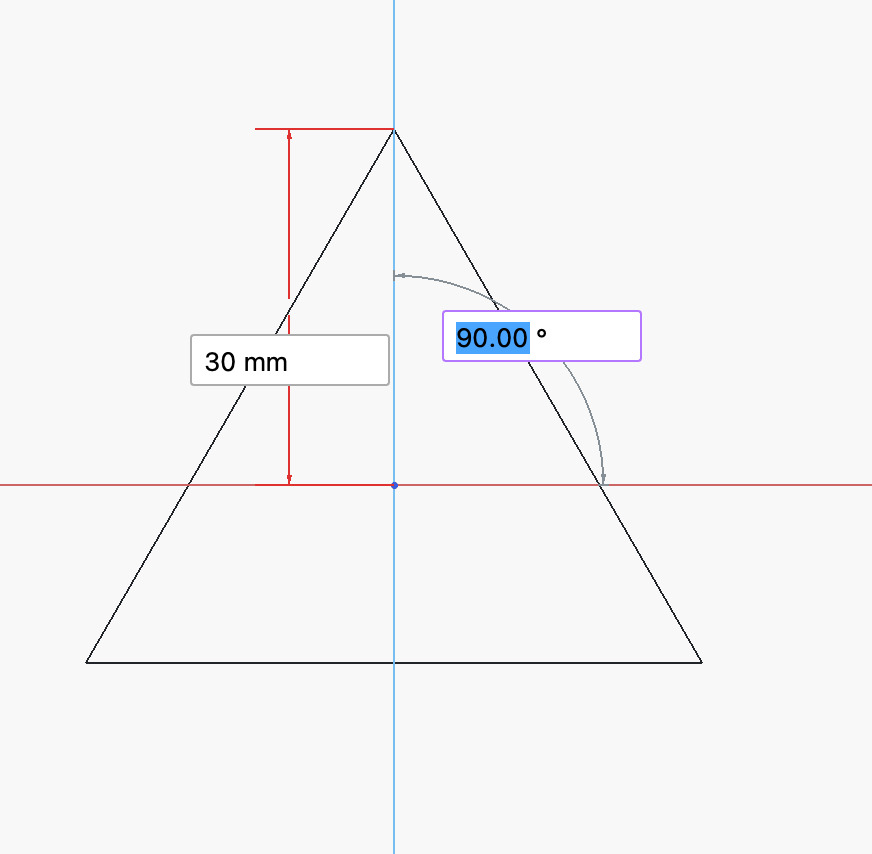
Sketch: Click sketch select your plane from the left hand menu and select triangle the dimension pops up immediately and the angle snaps nicely to 90 what a pleasure!
Loft: select the loft tool and make sure you click add section before you select the sketch for it to work.
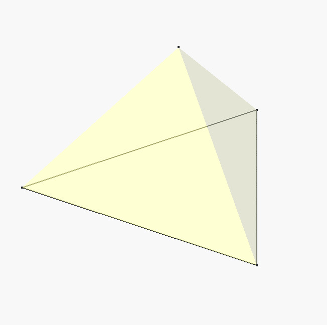
Verdict: Fantastic!
OpenSCAD
Overview:
- Precision: Best for geometric things because you can use direct equations instead of guessing.
- Units: Numbers are unitless in the code but treated as millimeters in slicer software like PrusaSlicer.
- Method: You "abuse" the fragment number ($fn) variable to force a cylinder to have only three sides.
- Code: If you like coding you will enjoy learning to design in this way.
- Don’t use chat gpt for this… very bad
Workflow:
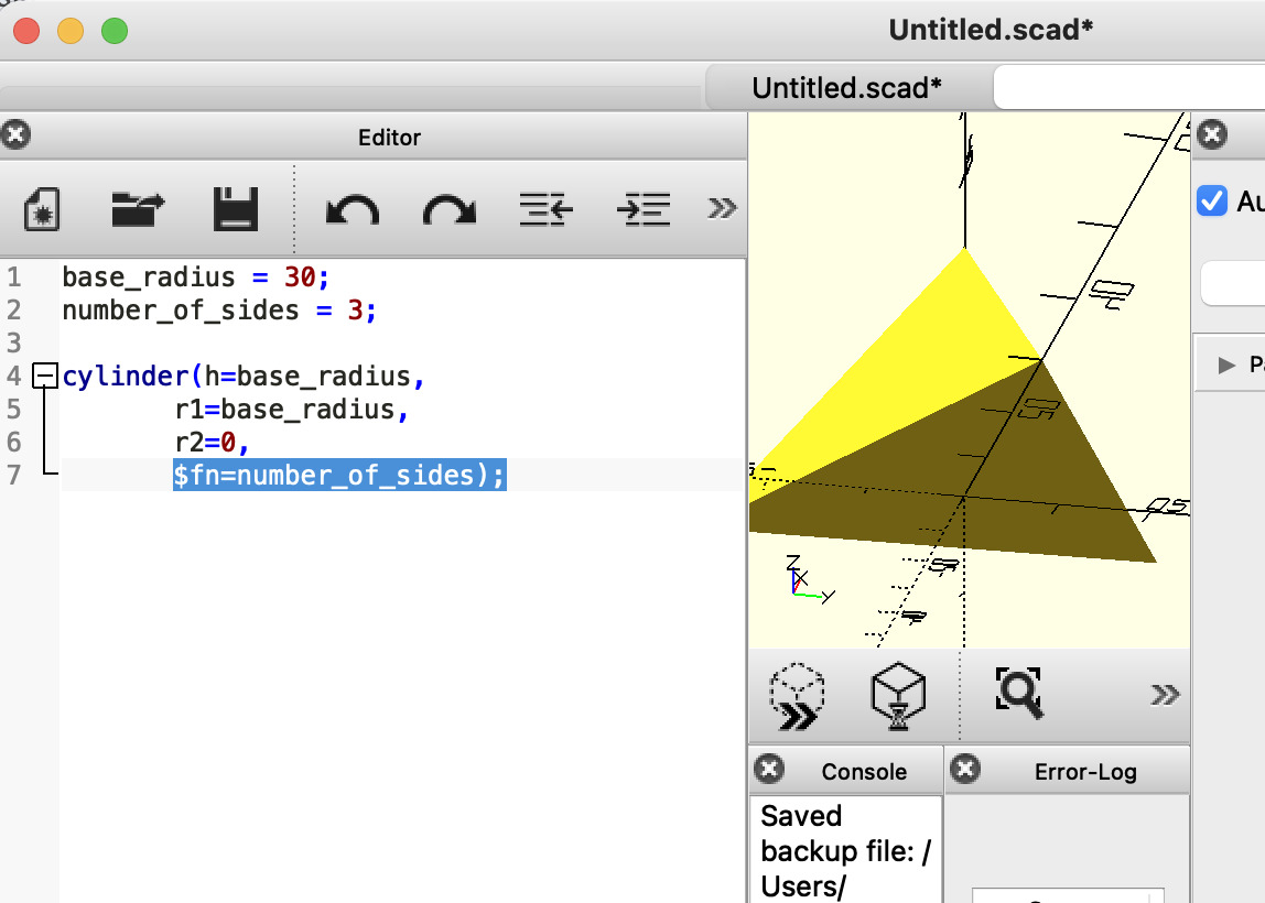
Base radius: Define the dimension of your base with:
base_radius = 30;
Number of sides: set the number of sides to 3 with.
number_of_sides = 3;
Create a Cylinder with one base: make the base radius and height the same and the to radius 0:
cylinder(h=base_radius, r1=base_radius, r2=0,
Set the number of sides to 3: use the fragment number ($fn) to change the number of sides to 3 creating a tetrahedron:
$fn=number_of_sides);
Verdict: Tricky but cool