Week_9: Input devices
For this weeks assignment we will be testing various input devices with the microcontroller we designed and produced. Since my project is an autonomous vehicle I will be testing sensors that could assist with navigation and movement and I will be using Thonny for the coding component
Gyroscope module
I purchased a GY-91 module from adafruit to test with this is a commonly used sensor with drones and other basic robotic projects commonly used in maker spaces and will be a good starting point
First I used Cirkitapp designer to create a nice wiring guide using its AI assistant
| GY-91 | XIAO Seeed RP2040 |
|---|---|
| VCC / VIN | 3V3 |
| GND | GND |
| SDA | D4 |
| SCL | D5 |
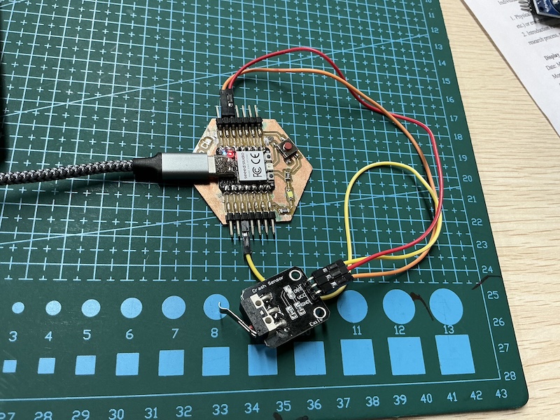
Then followed the wiring guide with my Xiao Cia
I then asked Chat gpt to code it so the data will be visible on the serial monitor in thonny giving this graphical display of the gyro data when the sensor is moved here is my prompt:
“I have a xiao seeed rp2040 using micropython and I am using the thonny IDE want to connect a gy-91 module and view the data graphically in the thonny IDE shell”
Accelerometer
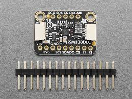
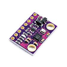
I purchased a “ISM330DLC” from taobao but I am sure its just a copy of the adafruit LSM6DSOX
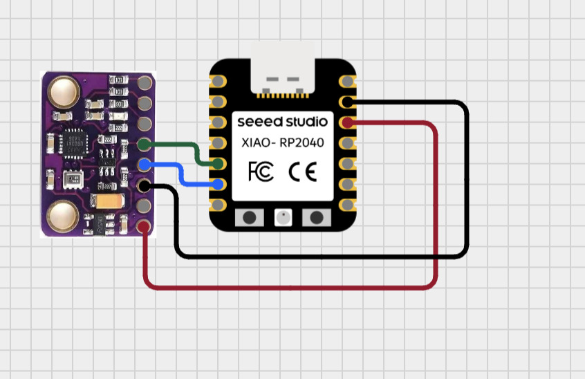
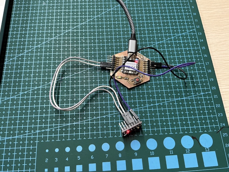
I did the same as for the gyroscope above creating the wiring diagram in Cirkitt designer
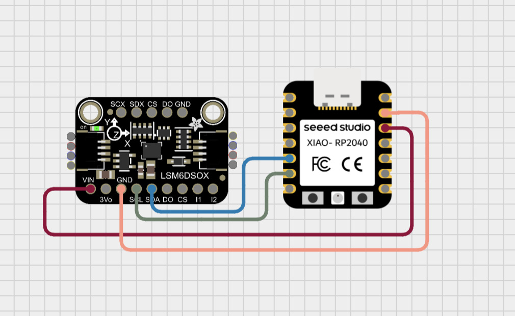
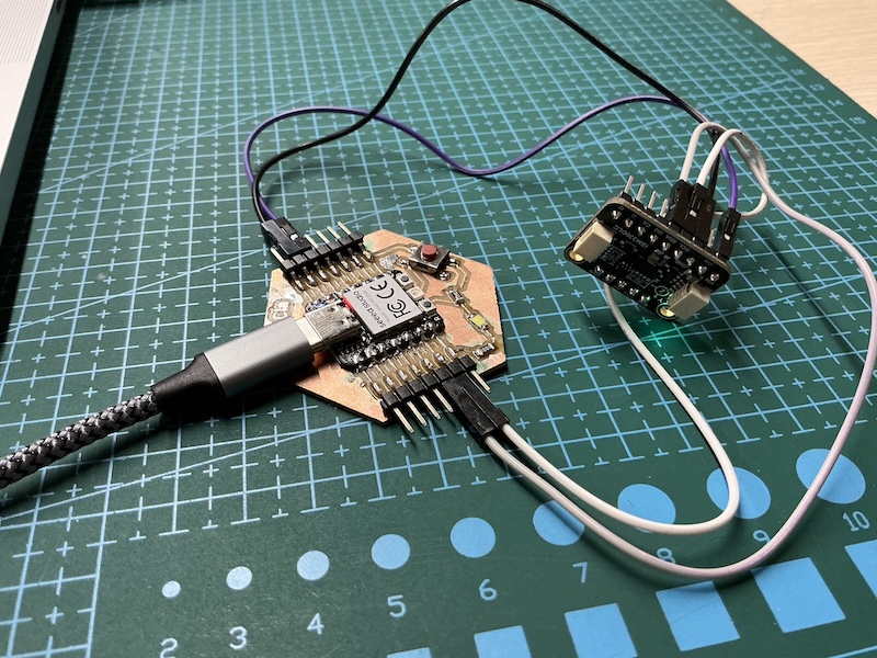
I then connected the pins according to the wiring diagram as seen below
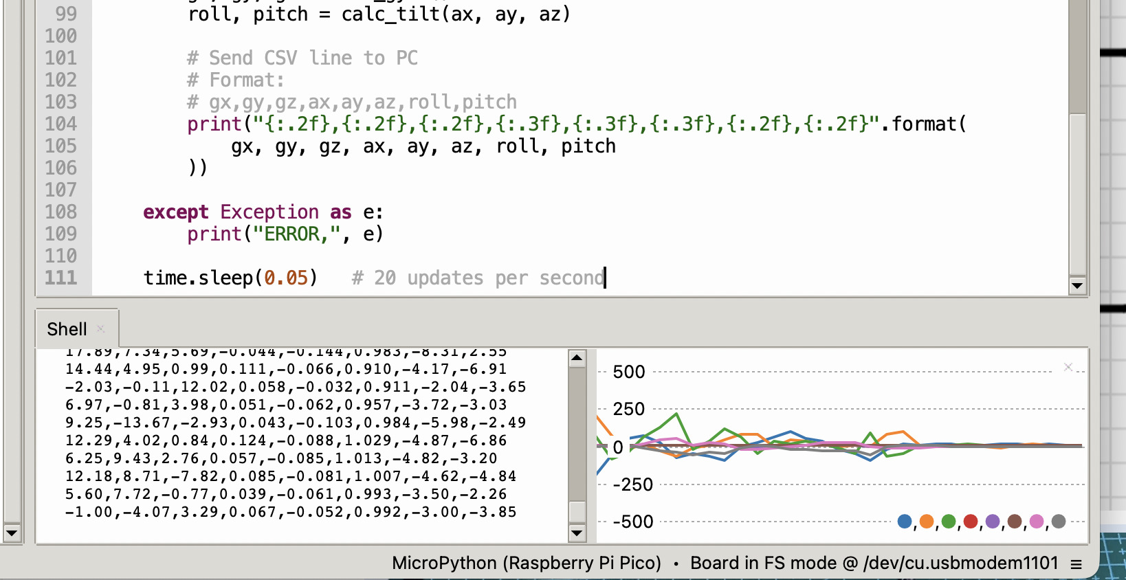
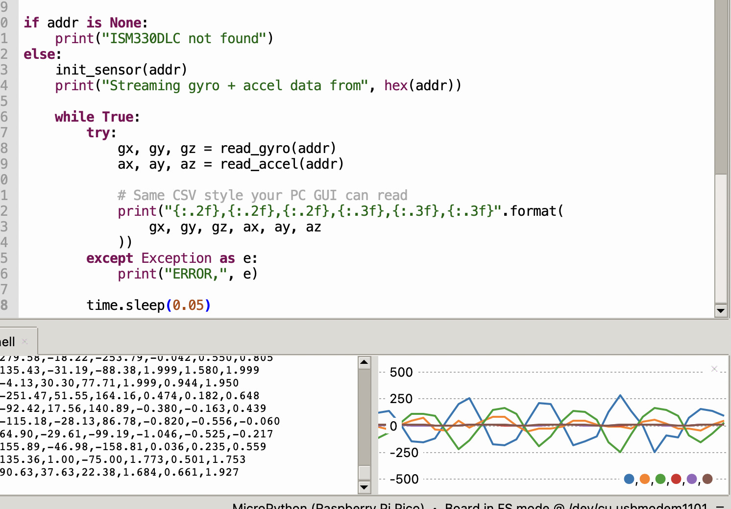
just as with the gyro module I asked chatgpt to supply code that would allow me to graphically see the accelerometer data in the Thonny IDE, my prompt:
“I have a xiao seeed rp2040 using micropython and I am using the thonny IDE want to connect a ISM330DLC module and view the data graphically in the thonny IDE shell”
Gas Sensor module:
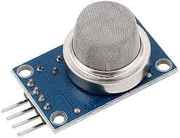
I would like my final project to be able to sense environmental conditions so a good place to start would be a gas sensor
Wiring guide
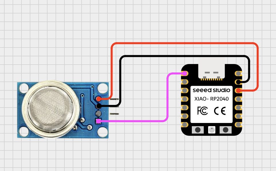
- VCC → 3.3V (VBUS pin)
- GND → GND
- DO → D0 (or any GPIO)
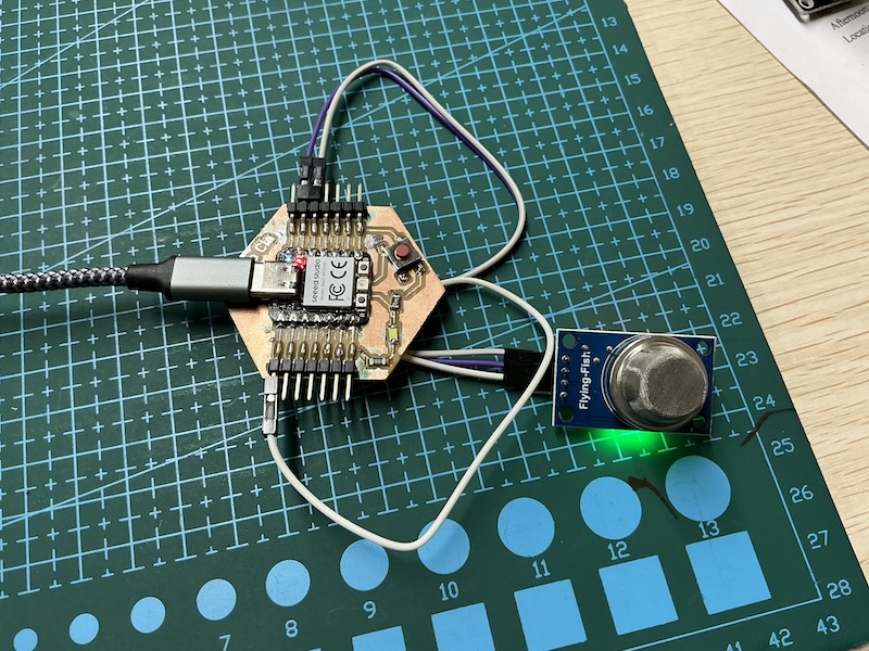
Success!
Crash sensor module:
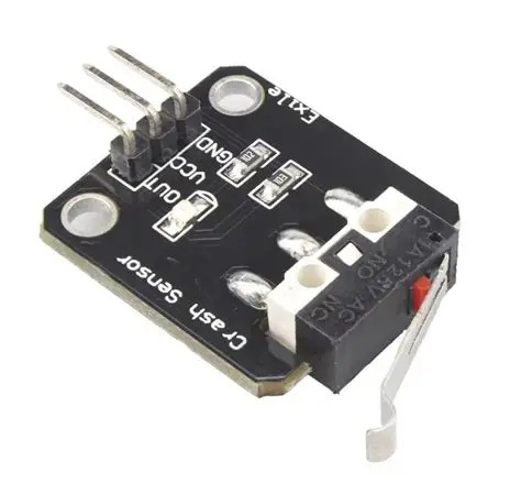
having bump/impact sensors on the hull of the boat might be a good Idea to help the boat navigate so I will attempt this with a simple crash sensor module
Wiring guide
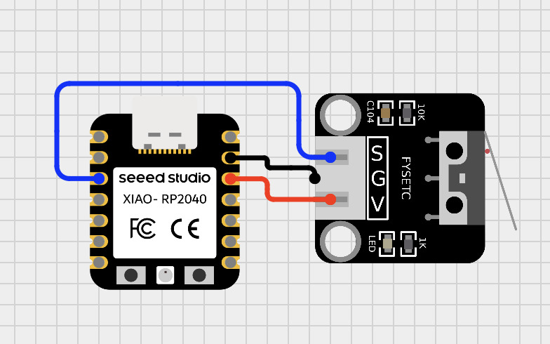
- Out → D2
- VCC → 3.3V
-
GND → GND
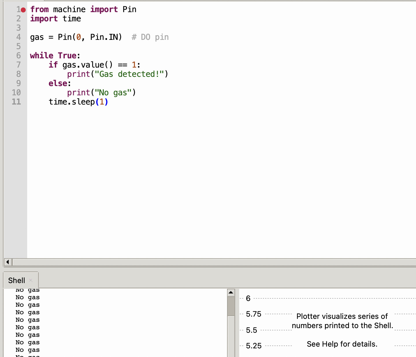
Import pin and time define the pin and make a simple loop
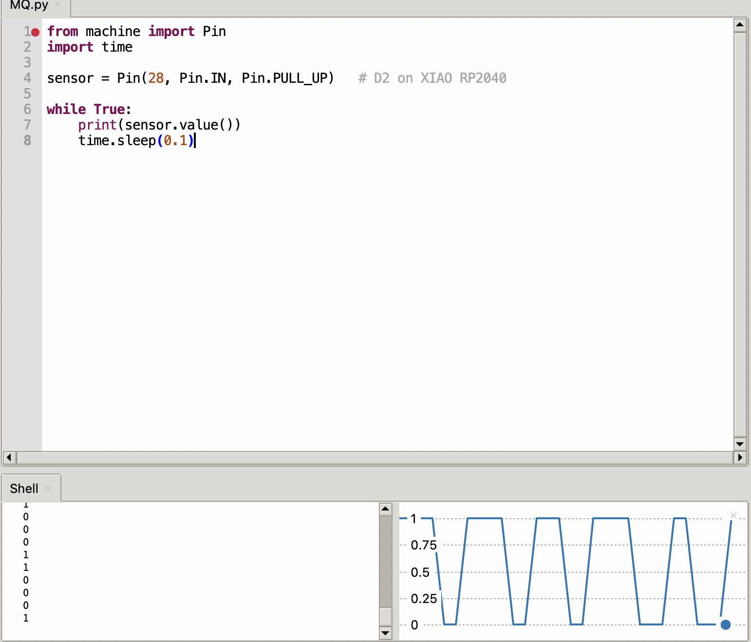
Joystick
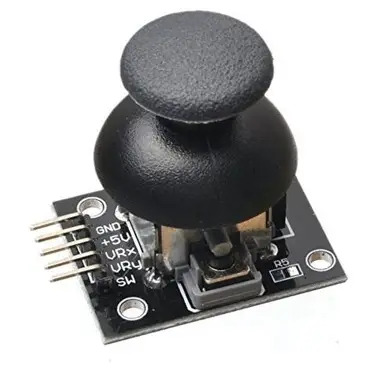
A joystick module is really useful as it can navigate on to axis and has a button input so if I have an embedded menu or sussed that utilizes a screen which I plan to do this could be a really useful input to be a part of my final project
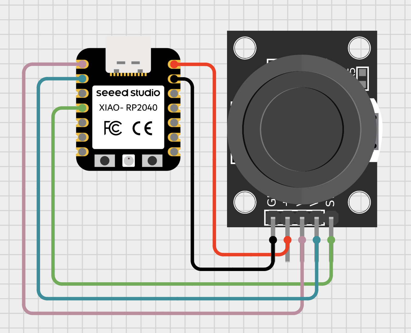
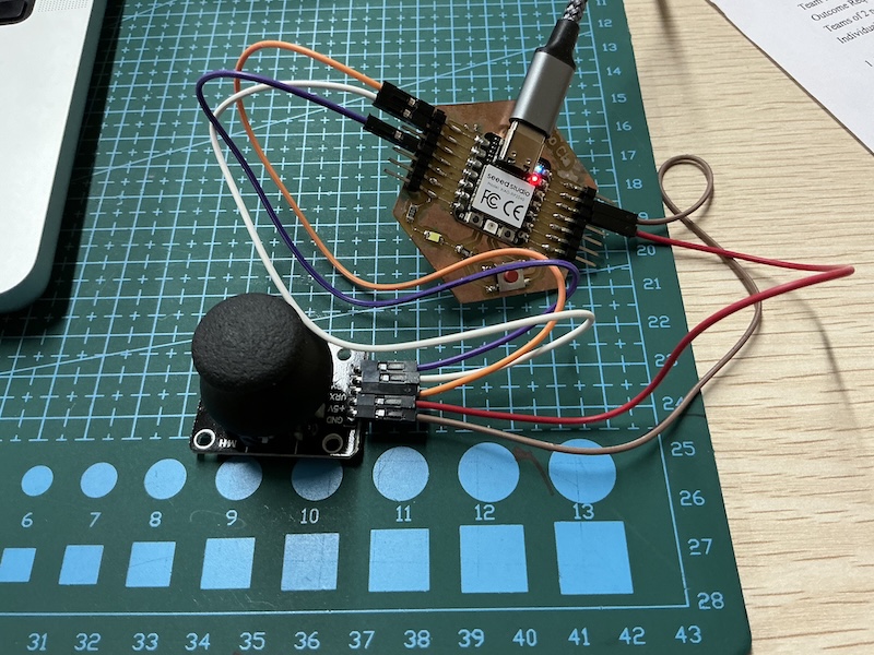
wiring guide
I made a visual wiring guide using the Cirkitt designer app but the VCC should be connected to 5V and the the VRX, VRY and SW pins can be connected to basically any of the Xiao seeed pins
| Joystick Pin | XIAO RP2040 Pin |
|---|---|
| VCC | 3V3 |
| GND | GND |
| VRx | A0 (GP26) |
| VRy | A1 (GP27) |
| SW | D3 (GP3) |
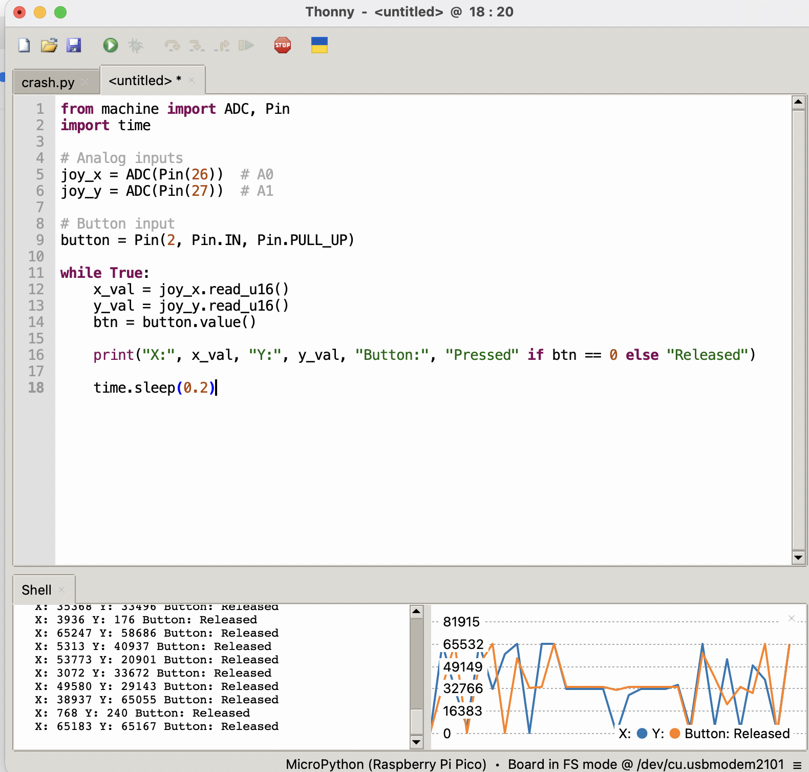
Coding:
I utilized chat got for the code and here is my prompt:
“
You are a MicroPython expert.
I am using a Seeed Studio XIAO RP2040 with a 5-pin joystick module.
The joystick is wired as follows:
- VRx → GPIO26 (ADC)
- VRy → GPIO27 (ADC)
- SW → GPIO2 (digital input with pull-up)
Write MicroPython code that:
- Reads the X and Y analog values using
read_u16() - Detects joystick direction: LEFT, RIGHT, UP, DOWN, CENTER
- Includes diagonal directions (e.g., UP-LEFT, DOWN-RIGHT)
- Uses appropriate threshold values and a dead zone
- Detects when the button is pressed (active LOW)
- Prints values in a clear format: X, Y, Direction, Button state
- Runs continuously with a short delay
Keep the code simple, clean, and well-commented.”
here is the result